
Related Manuals for Keysight M9484C


Summary of Contents for Keysight M9484C
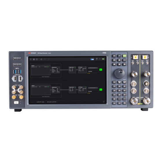
- Page 1 VXG Signal Generator M9484C VXG Vector Signal Generator This manual provides documentation for the M9484C running the Microsoft Windows 10 operating system. GETTING STARTED AND TROUBLESHOOTING GUIDE...
- Page 2 Notices DOCUMENT OR ANY INFORMATION commercial computer software or CONTAINED HEREIN. SHOULD commercial computer software KEYSIGHT AND THE USER HAVE A documentation. No additional © Keysight Technologies, Inc. SEPARATE WRITTEN AGREEMENT government requirements beyond 2021- 2022 WITH WARRANTY TERMS those set forth in the EULA shall...
- Page 3 Information on preventing instrument damage can be found at: http://keysight.com/find/PreventingInstrumentRepair Is your product software up-to-date? Periodically, Keysight releases software updates to fix known defects and incorporate product enhancements. To search for software updates for your product, go to the Keysight Technical Support website at: http://www.keysight.com/find/techsupport...
-
Page 5: Table Of Contents
1. Basic Measurements Overview ..............8 Equipment Setup . - Page 6 M9484B Millimeter Wave Signal Generator Startup Guide...
- Page 7 Keysight M9484C Millimeter Wave Vector Signal Generator Measurement Guide Basic Measurements “Equipment Setup” on page 9 — — “Setting Up Triggers on the X-Series Signal Analyzer” on page 11 “Making Measurements” on page 12 — — “Creating a Continuous Waveform (CW)” on page 12 —...
-
Page 8: Overview
Basic Measurements Overview Overview The M9484C VXG Vector Signal Generator provides frequency coverage from 9 kHz to 54 GHz, with up to 2.5 GHz RF modulation bandwidth per channel using an internal baseband generator, and up to 5 GHz RF modulation bandwidth with channel bonding. -
Page 9: Equipment Setup
Equipment Setup Equipment Setup — M9484C front panel RF 1 Out to X-Series Signal Analyzer front panel RF In — M9484C front panel Event 2 to X-Series Signal Analyzer rear panel Trig 1 In Trig 3 In is used for an N9040B with Option H1G (1 GHz Bandwidth). For N9040B with Bandwidth 510 MHz or less, use Trig 1 In. -
Page 10: Required Software
Basic Measurements Required Software Required Software — M9484C — N7631APPC - 5GNR — N7608APPC - Custom Modulation — N7605APOC - 3GPP Real Time/Fading — PathWave Automatic Channel Response Correction and S-parameter De-embedding (N7653APPC) M9484C Measurement Guide... -
Page 11: Setting Up Triggers On The X-Series Signal Analyzer
Screen tab (at the top of the display) to open the Mode/Measurement/View Selector window. 2. Select Mode Preset to set Spectrum Analyzer mode to a known state. 3. From the drop-down on the top right, select Trigger and set Trigger Source to Free Run. M9484C Measurement Guide... -
Page 12: Making Measurements
In order to turn on RF for any channel, both the RF Out for the specific channel (for example, Channel 1 or Channel 2), and RF Out All must be turned on. On the X-Series Signal Analyzer: 1. Select Mode Preset to set Spectrum Analyzer mode to a known state. M9484C Measurement Guide... - Page 13 2. Ensure that RF Out is On. On the X-Series Signal Analyzer: 1. Select Amplitude and set Ref Level to –70 dBm and Scale/Div 5 dB. 2. Select BW and set Video BW to 300 Hz. 3. Select Peak Search. M9484C Measurement Guide...
- Page 14 1. Select Frequency and set Center Frequency to 44 GHz. 2. Select Amplitude and set Ref Level to 0 dBm and Scale/Div to 10 dB. 3. Select BW > Video BW and set to Auto. 4. Select Peak Search. M9484C Measurement Guide...
- Page 15 Basic Measurements Making Measurements Observe the frequency and amplitude accuracy at high frequency levels. M9484C Measurement Guide...
- Page 16 RF1:POWer:AMPLitude -90dBm RF1:OUTPut:STATe ON On the X-Series Signal Analyzer: DISPlay:WINDow1:TRACe:Y:RLEVel -70 DISPlay:WINDow1:TRACe:Y:PDIVision 5 BWIDth:VIDeo 300Hz CALCulate:MARKer1:MAXimum On the VXG: RF1:FREQuency:CW 44GHZ RF1:POWer:AMPLitude 0dBm On the X-Series Signal Analyzer: FREQuency:CENTer 44GHZ DISPlay:WINDow1:TRACe:Y:RLEVel 0 DISPlay:WINDow1:TRACe:Y:PDIVision 10 BANDwidth:VIDeo:AUTO ON CALCulate:MARKer1:MAXimum M9484C Measurement Guide...
-
Page 17: Setting Up Amplitude Modulation
3. Select the Signal block. 4. Select the arrow for Signal 1 to open the Signal Setup window. This screen is only accessible if Option M9484C-8SG (8 virtual signal generators) is installed. For all other option configurations, continue to the next step. - Page 18 5. In the Mode dropdown, select Analog Modulation. 6. In the Analog Modulation Signal Setup: a. Set Modulation Type to AM. b. Set Waveform to Sine. c. Set Rate to 100 kHz. d. Set Depth to 50%. M9484C Measurement Guide...
- Page 19 VXG. On the X-Series Signal Analyzer: 1. Select Mode Preset to set Spectrum Analyzer mode to a known state. 2. Select Frequency and set Center Frequency to 20 GHz and Span to 500 kHz. M9484C Measurement Guide...
- Page 20 5. Use markers to measure sideband power relative to the center frequency by selecting Marker Delta. Select Next Pk Right until the second marker is at the next highest peak. The Delta Marker should be approximately –12 dB for 50% AM. M9484C Measurement Guide...
- Page 21 For multi-channel instruments, set RF Out (all) to On. RFALl:OUTPut ON On the X-Series Signal Analyzer: FREQuency:CENTer 20GHZ FREQuency:SPAN 500KHZ BANDwidth 100 Hz CALCulate:MARKer1:MODE DELTa CALCulate:MARKer1:MAXimum:RIGHt Repeat the above command until the marker is at the next highest peak. To retrieve the delta marker: CALCulate:MARKer1:Y? M9484C Measurement Guide...
-
Page 22: Setting Up Frequency Modulation
3. Select the Signal block. 4. Select the arrow for Signal 1 to open the Signal Setup window. This screen is only accessible if Option M9484C-8SG (8 virtual signal generators) is installed. For all other option configurations, continue to the next step. - Page 23 Basic Measurements Making Measurements 5. In the Mode dropdown, select Analog Modulation. a. Set Modulation Type to FM. b. Set Waveform to Sine. c. Set Rate to 400 Hz. d. Set Deviation to 10 MHz. M9484C Measurement Guide...
- Page 24 VXG. On the X-Series Signal Analyzer: 1. Select Mode Preset to set Spectrum Analyzer mode to a known state. 2. Select Frequency and set Center Frequency to 20 GHz and Span to 50 MHz. M9484C Measurement Guide...
- Page 25 SIGNal:MODE AMODulation SIGNal1:AMODulation:TYPE FM SIGNal1:FM:SHAPe SINE SIGNal1:FM:FREQuency 400HZ SIGNal1:FM 10MHZ SIGNal1 ON RF1:OUTPut:STATe ON For multi-channel instruments, set RF Out (all) to On. RFALl:OUTPut ON On the X-Series Signal Analyzer: FREQuency:CENTer 20GHZ FREQuency:SPAN 50MHZ ACPower:BANDwidth 240 Hz M9484C Measurement Guide...
-
Page 26: Setting Up Phase Modulation
3. Select the Signal block to open. 4. Select the arrow for Signal 1 to open the Signal Setup window. This screen is only accessible if Option M9484C-8SG (8 virtual signal generators) is installed. For all other option configurations, continue to the next step. - Page 27 Select Enable Vector Modulation Signal. 6. Close the Vector Modulation Signal Setup by selecting the Home icon at the top of the display. 7. Set RF Out to On by selecting the numbered channel indicator switch. M9484C Measurement Guide...
- Page 28 Analog Demod mode > PM Measurement > Quad View. If accessing the instrument via a Remote Desktop connection, select the Screen tab (at the top of the display) to open the Mode/Measurement/View Selector window. 4. Select Frequency and set Center Frequency to 20 GHz. M9484C Measurement Guide...
- Page 29 Basic Measurements Making Measurements M9484C Measurement Guide...
- Page 30 RF1:POWer:AMPLitude 0dBm SIGNal:MODE AMODulation SIGNal1:AMODulation:TYPE PM SIGNal1:PM:SHAPe SINE SIGNal1:PM:FREQuency 10KHZ SIGNal1:PM 1 SIGNal1 ON RF1:OUTPut:STATe ON For multi-channel instruments, set RF Out (all) to On. RFALl:OUTPut ON On the X-Series Signal Analyzer: INSTrument:CONFigure:ADEMOD:PM SYSTem:PRESet DISPlay:VIEW:ADVanced:SELect "QUAD" FREQuency:CENTer 20GHZ M9484C Measurement Guide...
-
Page 31: Setting Up Synchronized Pulse (Iq + Analog) Modulation
3. Select the Signal block to open. 4. Select the arrow for Signal 1 to open the Signal Setup window. This screen is only accessible if Option M9484C-8SG (8 virtual signal generators) is installed. For all other option configurations, continue to the next step. - Page 32 Basic Measurements Making Measurements 5. Select the Mode drop-down and select Waveform File. 6. In the Waveform Setup area, use File Select to navigate to: D:\Users\Instrument\Documents\Keysight\PathWave \SignalGenerator\Examples and choose M9484C Measurement Guide...
- Page 33 7. Set the Sample Rate to 2 kHz and select Enable Vector Modulation Signal. 8. Close the Vector Modulation Signal Setup by selecting the Home icon at the top of the display. 9. Set RF Out to On by selecting the numbered channel indicator switch. M9484C Measurement Guide...
- Page 34 3. Select Frequency and set Center Frequency to 1.0 GHz and Span to 0 Hz. 4. Select BW and set the Video BW to 300 Hz. 5. Select Sweep and set the Sweep Time to 4.0 s. M9484C Measurement Guide...
-
Page 35: Setting Up An Multitone Signal
3. Select the Signal block to open. 4. Select the arrow for Signal 1 to open the Signal Setup window. This screen is only accessible if Option M9484C-8SG (8 virtual signal generators) is installed. For all other option configurations, continue to the next step. - Page 36 8. Set RF Out to On by selecting the numbered channel indicator switch. This enables the RF Out for the indicated channels, in this case Channel 1 if using a multi-channel VXG. M9484C Measurement Guide...
- Page 37 1. Select Mode Preset to set Spectrum Analyzer mode to a known state. 2. Select Frequency and set Center Frequency to 20 GHz and Span to 10 MHz. 3. Select BW and set Res BW to 300 Hz and Video BW to 300 Hz. Observe the 15 tones. M9484C Measurement Guide...
- Page 38 SIGNal1:MTONe:ARB:FSP 500KHZ SIGNal1 ON RF1:OUTPut:STATe ON For multi-channel instruments, set RF Out (all) to On. RFALl:OUTPut ON On the X-Series Signal Analyzer: Change to Spectrum Analyzer mode, Swept SA measurement. INSTrument:CONFigure:SA:SAN DISPlay:VIEW:ADVanced:SELect “NORMAL” FREQuency:CENTer 20GHZ FREQuency:SPAN 10MHZ M9484C Measurement Guide...
-
Page 39: Setting Up Waveform File Vector Modulation
3. Select the Group 1: Signals block to open. 4. Select the arrow for Signal 1 to open the Signal Setup window. This screen is only accessible if Option M9484C-8SG (8 virtual signal generators) is installed. For all other option configurations, continue to the next step. - Page 40 5. In the Vector Modulation Signal Setup: a. Select the Mode dropdown and set to Waveform File. b. Use File Select to navigate to: D:\Users\Instrument\Documents\Keysight\PathWave \SignalGenerator\Examples c. Highlight GSM_1C_BURST_SECUREWAVE.wfm, then Select. d. Select Enable Vector Modulation Signal. M9484C Measurement Guide...
- Page 41 2. Select Frequency and set Center Frequency to 20 GHz and Span to 900 kHz. 3. Select BW and set Res BW to 470 Hz. 4. Select Trace and set Trace Type to Max Hold. 5. Observe the GSM signal. M9484C Measurement Guide...
- Page 42 1. Select the Group 1: Signals block to open. 2. Select the arrow for Signal 1 to open the Signal Setup window. This screen is only accessible if Option M9484C-8SG (8 virtual signal generators) is installed. For all other option configurations, continue to the next step.
- Page 43 5. Ensure that Enable Vector Modulation Signal is selected. 6. Ensure that RF Out is on. On the X-Series Signal Analyzer: 1. Select BW and set Res BW to 620 Hz. 2. Select Frequency and set Span to 30 MHz. M9484C Measurement Guide...
- Page 44 Basic Measurements Making Measurements 3. Observe the LTE signal. M9484C Measurement Guide...
- Page 45 RFALl:OUTPut ON On the X-Series Signal Analyzer: FREQuency:CENTer 20GHZ FREQuency:SPAN 900KHZ ACPower:BANDwidth 470 Hz DISPlay:TXPower:WINDow1:TRACe:MAXHold ON On the VXG: SIGN1:WAV " D:\Users\Instrument\Documents\Demo Waveforms\WDCMA_TM1_64DPCH_4C.wfm" SIGNal1 ON RF1:OUTPut:STATe ON On the X-Series Signal Analyzer: ACPower:BANDwidth 620 Hz FREQuency:SPAN 30MHZ M9484C Measurement Guide...
-
Page 46: Corrections/De-Embedding Using Pathwave N7653Appc Software
(real/imaginary) or MA (magnitude/angle) — (50) the characteristic impedance is 50 ohms If there is not a first line header, the default format is GHz, S-parameters, and magnitude/angle. 1. Create s2p files in Notepad in the format shown above. M9484C Measurement Guide... - Page 47 4. Select the Group 1: Signals block to open. 5. Select the arrow for Signal 1 to open the Signal Setup window. This screen is only accessible if Option M9484C-8SG (8 virtual signal generators) is installed. For all other option configurations, continue to the next step.
- Page 48 7. Close the Signal block by selecting the Home icon, and then select RF Out to turn on. 8. On the X-Series Signal Analyzer spectrum analyzer in Spectrum Analyzer Mode: — Select Mode Preset to set Spectrum Analyzer mode to a known state. — Set the Center to 10 GHz M9484C Measurement Guide...
- Page 49 Basic Measurements Making Measurements — Set Span to 3 GHz 9. On the VXG, select the RF Output block > Corrections/De-embedding. M9484C Measurement Guide...
- Page 50 Basic Measurements Making Measurements 10. In the Corrections Setup dialog, select Add from File. 11. Navigate and select the s2p file and then Select. D:\Users\Instrument\Documents\Keysight\PathWave \SignalGenerator\Examples\simpleAt10GHzInDB.s2p Notice that Block B is added in the Correction Setup diagram. M9484C Measurement Guide...
- Page 51 12. Turn Corrections On. View the results on the signal analyzer. Observe how the .s2p file has impacted the signal. 13. Add a third block using the same file name as shown in the steps above. Under Block C Properties, set to Embed. M9484C Measurement Guide...
- Page 52 When using a spectrum analyzer, it must be locked to the VXG Frequency Reference. This is important because the power measurement can be inaccurate due to a narrow resolution bandwidth (RBW) used in the spectrum analyzer. Supported Keysight X-Series signal analyzers are: — N9000A/B CXA — N9010A/B EXA —...
- Page 53 5. Select the Signal block to open. 6. Select the arrow for Signal 1 to open the Signal Setup window. This screen is only accessible if Option M9484C-8SG (8 virtual signal generators) is installed. For all other option configurations, continue to the next step.
- Page 54 Screen tab (at the top of the display) to open the Mode/Measurement/View Selector window. 2. Set the Center Frequency to 12 GHz and the Span to 3 GHz. Observe how the fixturing is impacting this signal, including the flatness and the total power. M9484C Measurement Guide...
- Page 55 Basic Measurements Making Measurements On the VXG: 1. Select the RF Output block > Corrections/De-embedding block to open the Correction Setup. 2. Select Add from Measurement to open the Measure Corrections Block Wizard. M9484C Measurement Guide...
- Page 56 (For this example, -10 dBm, which we already set in the main window. If you change the value here, it will update the value in the main measurement window.) and Number of Steps to 101. M9484C Measurement Guide...
- Page 57 Stop Frequencies for the specified number of steps and output power. It will take some time to measure all 101 points, and the progress is indicated by the blue bar. You can watch the signal analyzer as it steps through this process. M9484C Measurement Guide...
- Page 58 10. On the signal analyzer, Restart the (on the left corner of the user interface) measurement (because it is applying averaging). Observe how the measured corrections impacted the signal. You can easily toggle Corrections on and off on the VXG to see the difference. M9484C Measurement Guide...
- Page 59 — U2002H Using the graphical user interface On the VXG: 1. Connect the VXG 10 MHz Out to the N90x0A/B Ext Reference In. 2. Select the RF Output block > Corrections/De-embedding block to open the Correction Setup. M9484C Measurement Guide...
- Page 60 Basic Measurements Making Measurements 3. Select Add from Measurement to open the Measure Corrections Block Wizard. 4. Connect the power sensor as shown in the diagram below then select Next. M9484C Measurement Guide...
- Page 61 7. Select the Connection Type to USB, and then specify the Device and VISA Address. 8. Select Test Connection to verify connectivity, and then select OK then Next to continue. You can also calibrate and zero out the power sensor before measuring corrections. M9484C Measurement Guide...
- Page 62 Stop Frequencies for the specified number of steps and output power. The measurement results are saved to a csv file using an automatically generated file name. 10. Select Finish. The output csv file is set to Block A. M9484C Measurement Guide...
- Page 63 Basic Measurements Making Measurements Block A is dedicated for User Correction. The image below shows how blocks are assigned in the User Correction and Fixture block. 11. Select Corrections On to apply. M9484C Measurement Guide...
- Page 64 Set the power level to the highest level used in your measurement. RF1:POWer:AMPLitude 5dBm CORRection:PMDevice SANalyzer CORRection:FLATness:STEP:STARt 26GHZ CORRection:FLATness:STEP:STOP 30GHZ CORRection:FLATness:STEP:POINts 20 CORRection:SANalyzer:COMMunicate:TYPE SOCKets Set the LAN address and protocol parameters for your spectrum analyzer. CORRection:SANalyzer:COMMunicate:LAN:IP "192.168.1.5" CORRection:SANalyzer:COMMunicate:LAN:PORT 5025 CORRection:FLATness:CALibrate CORRection ON M9484C Measurement Guide...
- Page 65 Using a power meter to make the corrections measurement. On the VXG: SYSTem:PRESet RF1:POWer:AMPLitude 5dBm CORRection:PMDevice PMETer CORRection:FLATness:STEP:STARt 26GHZ CORRection:FLATness:STEP:STOP 30GHZ CORRection:FLATness:STEP:POINts 20 CORRection:SANalyzer:COMMunicate:TYPE USB Use query CORRection:PMETer:COMMunicate:USB:LIST? for a list of all connected USB devices. CORRection:PMETer:COMMunicate:USB:DEVice “instr0” [Optional] CORRection:PMETer:CALibrate [Optional] CORRection:PMETer:ZERO CORRection:FLATness:CALibrate CORRection ON M9484C Measurement Guide...
- Page 66 Set the path to the s2p data as block 2 (you can use 1 through 4). CORRection:BLOCk2:FILE "FixtureChannel2" CORRection:BLOCk2 ON Add block C with the same file. CORRection:BLOCk3:FILE "FixtureChannel2" Change Block C to Embed. CORRection:BLOCk3:APPLy EMBedding CORRection:BLOCk3 ON M9484C Measurement Guide...
-
Page 67: Instrument Nonlinear Correction
Instrument Nonlinear Correction Instrument Nonlinear Correction (INC) is a digital pre-distortion (DPD) based correction using a Keysight signal analyzer (N9042B, N9040B, or N9030B) to compensate for nonlinearities in the VXG. INC is useful in reducing EVM (and other metrics impacted distortion) at high power levels and extending the range of the power with linear output of the VXG. - Page 68 Basic Measurements Making Measurements 4. Select the arrow for Signal 1 to open the Signal Setup window. This screen is only accessible if Option M9484C-8SG (8 virtual signal generators) is installed. For all other option configurations, continue to the next step.
- Page 69 Basic Measurements Making Measurements 5G_100MHz_1CC_FR1.wfm then Select. 6. Select Enable Vector Modulation Signal. M9484C Measurement Guide...
- Page 70 PC running the VSA application. 4. Select Recall (If accessing the X-Series Signal Analyzer remotely, select the Folder icon at the bottom of the display) Demod Info > Data Type set to CC Setup > Recall From > M9484C Measurement Guide...
- Page 71 6. From the Main menu, select Meas Setup > Advanced tab > Advanced Demod Setup and set DC Punctured to On, then Close the Advanced Demod Setup window. 7. In the Meas Setup window, select the Settings tab > Optimize EVM. M9484C Measurement Guide...
- Page 72 Record the results. For this example EVM is 0.32% and EVM Peak is 1.79% To Measure ACP: a. Select Mode/Meas > 5GNR & V2X Mode > ACP > OK. µ b. Select Amplitude > Signal Path tab > and set W Path Control to Low Noise Path Enable. M9484C Measurement Guide...
- Page 73 Record the results for the Lower and Upper ACP results. For this example -50.9 dBc (lower) and -50.9(upper). c. Select Mode/Meas > 5GNR & V2X > Modulation Analysis > OK. On the VXG: 1. Open the Signal block and select Configure to open the Nonlinear Correction Setup. M9484C Measurement Guide...
- Page 74 Connection Type > Enter the IP address for you signal analyzer (for this example, 141.121.149.32) as the Hostname > Test Connection. The Connection status will be displayed in the Notifications area at the bottom of the main window. M9484C Measurement Guide...
- Page 75 .wfm file originally loaded. An "I" will be displayed in the Signal block indicating this status. On the UXA: 1. Select Optimize EVM. M9484C Measurement Guide...
- Page 76 EVM RMS is 0.24% (before 0.32%) and EVM Peak is 1.47% (before 1.79%). To Measure ACP: a. Select Mode/Meas > 5GNR & V2X Mode > ACP > OK. µ b. Select Amplitude > Signal Path tab > and set W Path Control to Low Noise Path Enable. M9484C Measurement Guide...
- Page 77 In order to compare before and after correction results, we will start by making an EVM measurement without applying corrections. 1. Select Preset > Preset to set the instrument to a know state. 2. In the Output area, set Frequency to 28 GHz and Power to 10 dBm. M9484C Measurement Guide...
- Page 78 3. Select the Group 1: Signals block to open. 4. Select the arrow for Signal 1 to open the Signal Setup window. This screen is only accessible if Option M9484C-8SG (8 virtual signal generators) is installed. For all other option configurations, continue to the next step.
- Page 79 Basic Measurements Making Measurements 5G_100MHz_8cc_FR2.wfm then Select. 7. Select Enable Vector Modulation Signal and close the Signal block. 8. Set RF Out to On. M9484C Measurement Guide...
- Page 80 Punctured to On, then Close the Advanced Demod Setup window. 7. Select the Sweep > Single Sweep. 8. Select Meas Setup > Settings tab > Optimize EVM. It will take a couple of minutes for the UXA to measure all 8 carriers. M9484C Measurement Guide...
- Page 81 Select Mode/Meas > 5GNR & V2X Mode > ACP > OK. µ b. Select Amplitude > Signal Path tab > and set W Path Control to LNP (Low Noise Path) Enable. c. Select Sweep > Restart to take a new sweep. M9484C Measurement Guide...
- Page 82 Making Measurements Note the values of the Lower and Upper ACP. For this example Lower, at 100 MHz offset is -26.7 dBc and Upper -27.06 dBc. d. Select Mode/Meas > 5GNR & V2X > Modulation Analysis > OK. M9484C Measurement Guide...
- Page 83 3. Under the Receiver tab (opened by default), enter your connection information and test the connection. For this example, select LAN as the Connection Type > Enter the IP address for you signal analyzer (for this example, 141.121.149.32) as the Hostname > Test Connection. M9484C Measurement Guide...
- Page 84 4. Select the Calibrations tab and select EVM and ACP for the Calibrations, then Start Calibration. On the UXA: 1. Select the Sweep > Restart. 2. Select Optimize EVM. Note the changes to EVM RMS and EVM Peak values. M9484C Measurement Guide...
- Page 85 Select Sweep > Restart to take a new sweep. Note the changes to the Lower and Upper ACP values. For this example Lower, at 100 MHz offset is -32.27 (before -26.7 dBc) and Upper -31.15 (before -27.06 dBc). M9484C Measurement Guide...
- Page 86 Basic Measurements Making Measurements M9484C Measurement Guide...
-
Page 87: Channel Bonding
For this measurement example, we are using the following equipment: — M9484C with options — Two channels (M9484C-001 and 002) — RF bandwidth of 2.5 GHz per channel (M9484C-R25) — Channel bonding, 5 GHz (M9484C-CB5 and M9484C-PCH) — PathWave Signal Generation for Custom Modulation (N7608APPC) —... - Page 88 Other applications include Direct to Home (DTH), Digital Satellite News Gathering (DSNG) and professional VSAT. On the VXG: 1. Connect the equipment as shown above. 2. Select Preset > Preset to set the VXG to a known state. M9484C Measurement Guide...
- Page 89 3. Select the System menu (triple bar tab at the top left of the window), and then select Configure Channels > Group 1:2 Channel Bonded > Apply Configuration. 4. Set the Center Frequency to 25 GHz and Power to 0 dBm. M9484C Measurement Guide...
- Page 90 You can view all of your available applications by selecting the Apps tab. 6. In the Custom Modulation setup, select the Carrier tab > Quick Setups > DVB-S2X > 32APSK > 4+8+4+16APSK 140/180. M9484C Measurement Guide...
- Page 91 Each channel is 2.56 GHz for a combined sample rate of 5.12 GHz. This could be set by entering 5.12 GHz as the User Defined Sample Rate however; for Multi-carrier it is best to set the Oversampling Ratio. 11. From the left pane, select Multi Carrier and select Multicarrier Enabled. M9484C Measurement Guide...
- Page 92 12. Open the Frequency Offsets setup screen. For Carrier Index 0, set the Frequency Offset to -1200 MHz, then select Add Rows. 13. Enter the 1st Frequency Offset of -600 MHz, # of Carriers 4, and Carrier Spacing 600 MHz. Select Add. All five carriers will be setup. M9484C Measurement Guide...
- Page 93 14. Generate the waveform and select the Spectrum tab from the bottom pane to ensure the resulting waveform is correct. 15. Select the Home icon to return to the main window and then select the Signal Block to open. M9484C Measurement Guide...
- Page 94 Basic Measurements Making Measurements 16. In the Signal Setup dialog box, notice that new custom modulation file is already selected (CustomMod_G1S1.wfm). Set the Occupied Bandwidth to 3 GHz. M9484C Measurement Guide...
- Page 95 UXA, then Test Connection. Ensure that you have successfully connected to the UXA, a message will be displayed in the Status area at the bottom of the display. 18. Select the Calibrations tab and clear the ACP calibration. M9484C Measurement Guide...
- Page 96 Notice that the CustomMod_G1S1.bnd waveform is now playing. On the Signal Analyzer: 1. Select Frequency > Auto Tune to observe the spectrum. Ensure that signal analyzer is set to Spectrum Analyzer mode > Swept SA Measurement > View Normal. M9484C Measurement Guide...
- Page 97 2. Open the VSA software by selecting Mode Meas > Launch VSA. If accessing the instrument via a Remote Desktop connection, select the Screen tab (at the top left of the display) to open the Mode/Measurement/View Selector window. M9484C Measurement Guide...
- Page 98 Basic Measurements Making Measurements 3. In the Spectrum window, select Center frequency and set to 12 GHz, then select Auto-range. M9484C Measurement Guide...
- Page 99 In the Format tab, select Constellation Edit. b. Select Preset to Standard Constellation > DVB S2X APSK > 32APSK (4+8+4+16) > 32APSK 7/9. This is equivalent to the 4+8+4+16APSK 140/180 setting we chose in the Custom Modulation setup. M9484C Measurement Guide...
- Page 100 Turn off Pulse Search Enable (checkbox cleared). e. Set the Result Length to 2000 Symbols. f. Set the Symbol Rate to 500 MHz. The Result Length and Symbol Rate will adjust the resolution bandwidth to better define the waveform. M9484C Measurement Guide...
- Page 101 6. In the CustomIQMeas Time window, click on I-Q and change to Constellation, if desired. 7. Change the window layout to Grid 2x2. 8. Note the measured EVM value in the CustomIQSyms/Errs window. For this example, 1.2%rms. M9484C Measurement Guide...
- Page 102 Basic Measurements Making Measurements M9484C Measurement Guide...
- Page 103 3. Select the System menu (triple bar tab at the top left of the window), and then select Configure Channels > Group 1:2 Channel Bonded > Apply Configuration. 4. Set the Center Frequency to 12 GHz and Power to 0 dBm. M9484C Measurement Guide...
- Page 104 Apps tab. 6. In the Custom Modulation setup, select the Carrier tab > Quick Setups > DVB-S2 > QPSK. 7. From the bottom pane, select Remove Segment to remove the Header. This will simplify the demonstration. M9484C Measurement Guide...
- Page 105 9. Select Filter > Alpha to 0.2. 10. Select the Waveform tab > Basic > Select User Defined Sample Rate and set Sample Rate to 5.12 GSa/s. Each channel is 2.56 GHz for a combined sample rate of 5.12 GHz. M9484C Measurement Guide...
- Page 106 14. Set the Occupied Bandwidth to 3.6 GHz (or 1.2 x 3 GHz) and the Sample Rate to 5.12 GHz Samples per second. 15. Select Configure Channel Bonding and configure the Hostname or IP address for the UXA, then Test Connection. Ensure that you have successfully connected to the UXA. M9484C Measurement Guide...
- Page 107 The calibration takes a few minutes to complete. Note that the VXG displays an Invalid file selection message. This is because the VXG no longer sees the .wfm waveform instead the newly calibrated waveform has a .bnd file extension. Notice that the CustomMod_G1S1.bnd waveform is now playing. M9484C Measurement Guide...
- Page 108 2. Open the VSA software by selecting Mode Meas > Launch VSA. If accessing the instrument via a Remote Desktop connection, select the Screen tab (at the top left of the display) to open the Mode/Measurement/View Selector window. M9484C Measurement Guide...
- Page 109 5. From the menu bar, select MeasSetup > Custom IQ Demod Properties. a. Select the Format tab and select Constellation Edit. b. Select Preset to Standard Constellation > PSK > QPSK. c. Select OK to close the Constellation Edit dialog. d. Turn off Pulse Search Enable (checkbox cleared). M9484C Measurement Guide...
- Page 110 Basic Measurements Making Measurements e. Set the Symbol Rate to 3 GHz. f. Select the Filter tab and set Alpha/BT to 0.2, Filter Length to 33, Equalizer Type to Minimize Error Vector, and Reset the Filter. M9484C Measurement Guide...
- Page 111 7. In the menu bar, select the Trace Layout icon and select the Grid 2 x 2 format. This allows you to view more measurement details like the EVM results, which for this example is ~1.6 %rms. M9484C Measurement Guide...
- Page 112 Basic Measurements Making Measurements M9484C Measurement Guide...
- Page 113 2. Select Preset > Preset to set the VXG to a known state. If a Synchronization Alignment is required, indicated by in the bottom left corner, tap or click the warning message and choose Perform Alignment before proceeding. M9484C Measurement Guide...
- Page 114 If you have previously opened any of your available applications, the dialog box will not be displayed. Instead, you will see tabs of the applications that have already been used. You can view all of your available applications by selecting the Apps tab. M9484C Measurement Guide...
- Page 115 8. Select DL Test Model to open. set Bandwidth to FR2 400 MHz and set Phase Compensation to Off, and then select OK. 9. Select the Waveform Tab, and set the Time Scale Factor to 10. M9484C Measurement Guide...
- Page 116 Signal Setup (*.scp) file. In the File Name field, create a name for the setup file, then select Enter. Note the location where you saved this file as you will need to copy it to the UXA. M9484C Measurement Guide...
- Page 117 14. In the Signal Setup dialog box, notice that new custom modulation file is already selected (NR5G_G1S1.wfm). 15. Select Configure Channel Bonding and configure the Hostname or IP address for the UXA, then Test Connection. Ensure that you have successfully connected to the UXA. M9484C Measurement Guide...
- Page 118 16. Select the Calibrations tab and clear the ACP calibration, then select Start Calibration. On the Signal Analyzer: Below are two methods for viewing the results of the 5G NR wideband waveform. — Using X-Apps 5G NR & V2X Modulation mode Modulation Analysis measurement — Using 89600 VSA M9484C Measurement Guide...
- Page 119 NR & V2X Mode > Modulation Analysis Measurement > OK. 5. Select Recall (If accessing the N9042B remotely, select the Folder icon at the bottom of the display) Demod Info > Data Type set to CC Setup > Recall From. M9484C Measurement Guide...
- Page 120 6. Navigate to the .scp file you created in above and select Recall. step 11 7. From the Menu Panel, select Meas Setup > Settings tab > Optimize EVM. For this example, the EVM RMS is ~1.9%. M9484C Measurement Guide...
- Page 121 VXG. 4. From the menu bar, select MeasSetup > 5G NR Demod Properties > Time tab and set Time Scale Factor to 10. Close the Demod Properties windows and observe the results. M9484C Measurement Guide...
- Page 122 Basic Measurements Making Measurements 5. In the Spectrum window, set the Span to 4 GHz, then select the Auto-range icon at the top of the display. In this example, the EVM is ~2% M9484C Measurement Guide...
-
Page 123: Group Delay
— The measurement trace depicts the amount of time it takes for each frequency to travel through the device under test. In this measurement example, we will use the M9484C VXG to generate a wideband modulated signal, drive this through a filter and the N9042B UXA will analyze the output signal and display the filter characteristics (gain, phase, and group-delay). - Page 124 "noise" at the edges. 5. Select Connection Management. 6. In the New Signal Generator area, specify the Hostname or IP address of the VXG, then select Add to Generator List > Connect. M9484C Measurement Guide...
- Page 125 Notice that the span has automatically changed to 626.3 MHz to accommodate the Tone settings. 9. Select Configure Tone Table. There are lots of settings to choose from, but we will use these default settings. M9484C Measurement Guide...
- Page 126 The calibration will calculate the difference between tone definition and average input trace (magnitude and phase). 13. Once the calibration is complete, Close the Configure Tone table and connect the filter between the two 3 dB attenuators to see the response of the filter. M9484C Measurement Guide...
- Page 127 Trace to Gain Phase. Click and drag Marker 1 to the Reference Marker 2 position. Activate Marker 2 by setting Marker Mode to Delta, then set Marker Trace to Gain Phase to put the marker on the Gain Phase measurement, then Close the window. M9484C Measurement Guide...
- Page 128 17. Move Marker 1 to the Peak of the Signal within the bandwidth range of the signal and Marker 2 to the minimum. This provides the peak-to-peak deviation across this portion of the bandwidth of the filter. For this example, Peak to Peak Deviation is ° 54.69 M9484C Measurement Guide...
- Page 129 Normal and Marker Trace to Avg Group Delay. Drag Marker 3 to Marker 4’s Reference Position. Turn on Marker 4 and set Marker Mode to Delta and Marker Trace to Avg Group Delay. Close the Marker Settings Diagram. M9484C Measurement Guide...
- Page 130 Basic Measurements Making Measurements 19. Move Marker 3 to the peak of the trace and Marker 4 to the minimum. For this example, peak to peak Average Group Delay is 4.42 ns. M9484C Measurement Guide...
- Page 131 21. Turn Instantaneous Trace Off and Averaged Trace On then set the Aperture to 10% to get a smoother result, but lose a little bit more at the beginning and the end of the 500 MHz band. M9484C Measurement Guide...
- Page 132 Basic Measurements Making Measurements The Group Delay Aperture is the span over which the math of the delta phase over delta frequency is calculated. M9484C Measurement Guide...
- Page 133 However as it averages down, the noise will average away. 23. From the N9042B, select Mode/Meas > Channel Quality/Group Delay Mode > Group Delay Measurement > 3x2 View. M9484C Measurement Guide...
-
Page 134: Setting Up 8 Virtual Signal Generators
Setting Up 8 Virtual Signal Generators The M9484C Option 8SG provides eight virtual signal generators (multiple IQ paths to RF) allowing you to emulate up to 8 signals simultaneously with one channel. This feature is most beneficial in receiver design and test applications in which the current implementation often involves RF combining of multiple signal generators due to dynamic range limitations. - Page 135 Basic Measurements Making Measurements For this example we will use the following equipment: — M9484C VXG — RF bandwidth of 2.5 GHz per channel (M9484C-R25) — 8 Virtual Signal Generators (M9484C-8SG) — N7631APPC PathWave Signal Generation for 5G NR measurement application —...
- Page 136 5. Select the Mode drop down menu and select Waveform File. 6. In the Waveform Playback Setup area, use File Select to navigate to: D:\Users\Instrument\Documents\Keysight\PathWave \SignalGenerator\Examples and choose 01_GSM_Framed_slots 1 3 5 off_EDGE Framed_slots 0 2 4 6 off_2MHz separation_WFM1.wfm then Select. M9484C Measurement Guide...
- Page 137 2.9956 GHz now that Signal 1 is consuming 4.333 MHz. 10. Repeat step step 4 through step 9 for Signal 2, Signal 3, and Signal 4 with the following changes. — Signal 2 — Waveform: D:\Users\Instrument\Documents\Keysight\PathWave \SignalGenerator\Examples\02_W-CDMA_TM1_1 DPCH.wfm — Frequency Offset: –1.0 GHz — Signal 3 M9484C Measurement Guide...
- Page 138 — Frequency Offset: 1.0 GHz 11. Signals 5 -7 will be configured using the embedded PathWave Signal Generation for 5G NR (N7631APPC). Select the Radio Apps icon in the top left of the window, and then select 5G NR. M9484C Measurement Guide...
- Page 139 You can view all of your available applications by selecting the Apps tab. 12. To create signal 5, select the Carrier tab > Full-filled Config and set — Bandwidth to FR1 100 MHz — Duplex Type to FDD — Modulation to 64QAM, then select OK M9484C Measurement Guide...
- Page 140 17. To create signal 7, select the Carrier tab > Full-filled Config and set Bandwidth to FR2 400 MHz. 18. Select the Waveform tab, then from the left pane, select the Routing tab, set the signal number to 7, and then Generate. M9484C Measurement Guide...
- Page 141 — Signal 6 to –300 MHz — Signal 7 to 300 MHz 20. Select the arrow for Signal 8. 21. Select the Mode drop down and select AWGN. Set Channel Bandwidth to 1.5 GHz and Frequency Offset to -200 MHz. M9484C Measurement Guide...
- Page 142 Bandwidth such that the AWGN Sample Rate is less than the Remaining Sample Rate shown in the previous step allows for the Enable box to be selected (checked). 22. Select Enable to turn on Signal Mode for the AWGN signal. M9484C Measurement Guide...
- Page 143 If accessing the instrument via a Remote Desktop connection, select the Screen tab (at the top of the display) to open the Mode/Measurement/View Selector window. 2. Select Mode Preset to set the spectrum analyzer to a known state. M9484C Measurement Guide...
- Page 144 — Use the Auto Configure Analyzer feature to demodulate one of the 5G NR signals. Note, the center frequency will need to be manually adjusted on the Signal Analyzer to match the Frequency Offset of the signal set on the VXG. — Change Trigger and/or Marker settings. M9484C Measurement Guide...
- Page 145 Keysight M9484C Millimeter Wave Vector Signal Generator Measurement Guide 5G New Radio (NR) Measurements using X-Apps This section includes the following topics: — “5G Waveform, EVM, and ACP Analysis Using X-Applications” on page 146 — “Setting Up Triggers on the Signal Analyzer using 5G NR Mode” on page 146 —...
-
Page 146: G New Radio (Nr) Measurements Using X-Apps
3. Select Mode/Meas > 5G NR V2X Mode > Modulation Analysis Measurement. 4. From the Menu Panel (on the top right of the display), select Trigger and set Select Trigger Source to External 1 and Trigger Level to 1 V. M9484C Measurement Guide... - Page 147 5G New Radio (NR) Measurements using X-Apps 5G Waveform, EVM, and ACP Analysis Using X-Applications Using the equivalent SCPI commands On the X-Series Signal Analyzer: INSTrument:CONFigure:NR SYSTem:PRESet Change the current window to 5G NR Modulation Analysis Measurement Mode INSTrument:CONFigure:NR5G:EVM TRIGger:EVM:SOURce EXTernal1 TRIGger:EXTernal1:LEVel 1V M9484C Measurement Guide...
-
Page 148: Setting Up A 1 Cc 28 Ghz Evm Measurement
3. Select Group 1: Signals block to open. 4. Select the arrow for Signal 1 to open the Signal Setup window. This screen is only accessible if Option M9484C-8SG (8 virtual signal generators) is installed. For all other option configurations, continue to the next step. - Page 149 5G New Radio (NR) Measurements using X-Apps 5G Waveform, EVM, and ACP Analysis Using X-Applications 5. In the Waveform Playback Setup area, use File Select to navigate to: D:\Users\Instrument\Documents\Keysight\PathWave \SignalGenerator\Examples and choose 5GNR_1CC_FR2_120kHz_SCS_100MHz_256QAM_DCPunctured_28GHz.wfm then Select. M9484C Measurement Guide...
- Page 150 EVM. This is due to the dynamic range implications as it relates to signal to noise ratio. The greater the RF hardware variations in flatness, the greater the amount of correction is required, the greater the correction effectively reduces the number of M9484C Measurement Guide...
- Page 151 RF Out (All) to On by selecting the switch. In order to turn on RF for any channel, both the RF Out for the specific channel (for example, Channel 1 or Channel 2), and RF Out All must be turned on. M9484C Measurement Guide...
- Page 152 — Search Length to 10 ms — Result Length to 2 Sub Frame — Frame Trigger to On 3. Ensure that RF for Phase Compensation Auto is not selected and the value is 0 Hz. Close the Advanced Settings table. M9484C Measurement Guide...
- Page 153 4. Select the Settings tab > Optimize EVM. The Optimize EVM function automatically sets the combination of preamplification, mechanical and electronic attenuation, and IF gain based on the measured signal peak level. EVM should be less than 1%. M9484C Measurement Guide...
- Page 154 You will need to copy over the setup files to the X-Series Signal AnalyzerX-Series Signal Analyzer or the PC running the VSA application. MMEMory:LOAD:EVM:SETup CC0, “D:\Users\Instrument\Documents\NR5G\data\NR5GEvm\CarrierSetu p\5GNR_1CC_FR2_120kHz SCS_100MHz_256QAM_DCpunctured_28GHz.scp” EVM:CCARrier0:TIME:LENGth:SEARch 10ms EVM:CCARrier0:TIME:LENGth:RESult 2 EVM:CCARrier0:FRAMe:TRIGger ON EVM:CCARrier0:DC:PUNCture ON EVM:CCARrier0:PHASe:COMPensation:AUTO OFF EVM:CCARrier0:PHASe:COMPensation:FREQuency 0 Hz EVM:OPTimize M9484C Measurement Guide...
-
Page 155: Setting Up An 8 Cc 28 Ghz Evm Measurement
3. Select Group 1: Signals block to open. 4. Select the arrow for Signal 1 to open the Signal Setup window. This screen is only accessible if Option M9484C-8SG (8 virtual signal generators) is installed. For all other option configurations, continue to the next step. - Page 156 5G Waveform, EVM, and ACP Analysis Using X-Applications 5. Use File Select to navigate to: D:\Users\Instrument\Documents\Keysight\PathWave \SignalGenerator\Examples and choose 5GNR_8CC_FR2_120kHz_SCS_100MHz_256QAM_Corrected_28GHz. then Select. 6. Select Enable Vector Modulation Signal. 7. Close the Signal Setup by selecting the Home icon at the top of the display. M9484C Measurement Guide...
- Page 157 10. Set RF Out to On by selecting the numbered channel indicator switch. This enables the RF Out for the indicated channels, in this case Channel 1 if using a multi-channel VXG. M9484C Measurement Guide...
- Page 158 VSA application. 1. Select Recall (If accessing the signal analyzer remotely, select the Folder icon at the bottom of the display) > Demod Info > set Data Type to CC Setup > Recall From > 8CC_FR2_120kHz_SCS_100MHz_256QAM_Corrected_28GHz_34.scp > Recall. M9484C Measurement Guide...
- Page 159 3. Select Meas Setup > Advanced tab > Advanced Demod Setup and select both Multi-Carrier Filter and DC Punctured to turn on. The multi-carrier filter is used to filter out the unwanted carriers and minimize leakage into the component carrier of interest. M9484C Measurement Guide...
- Page 160 6. Select Meas Setup > Settings tab > Optimize EVM. It will take a couple of minutes for the UXA to measure all 8 carriers. Notice that the Error Summary measurement has a scroll bar allowing you to view the results of all 8 component carriers. M9484C Measurement Guide...
- Page 161 5G New Radio (NR) Measurements using X-Apps 5G Waveform, EVM, and ACP Analysis Using X-Applications M9484C Measurement Guide...
- Page 162 You will need to copy over the setup files to the X-Series Signal Analyzer or the PC running the VSA application. Navigate to the desired waveform file. MMEMory:LOAD:EVM:SETup CC0, “D:\Users\Instrument\Documents\NR5G\data\NR5GEvm\CarrierSetu p\8CC_FR2_120kHz_SCS_100MHz_256QAM_Corrected_28GHz_34.scp ” EVM:CCARrier0:TIME:LENGth:SEARch 10ms EVM:CCARrier0:TIME:LENGth:RESult 2 EVM:CCARrier0:FRAMe:TRIGger ON EVM:CCARrier0:MCFilter ON EVM:CCARrier0:DC:PUNCture ON EVM:CCARrier0:PHASe:COMPensation:AUTO OFF EVM:CCARrier0:PHASe:COMPensation:FREQuency 0 Hz M9484C Measurement Guide...
- Page 163 5G New Radio (NR) Measurements using X-Apps 5G Waveform, EVM, and ACP Analysis Using X-Applications To Optimize EVM for Multi-Carrier Waveforms POWer:ATTenuation 0dB [POWer:ATTenuation 2dB], … EVM:IF:GAIN:LEVel 0dB M9484C Measurement Guide...
-
Page 164: Setting Up A 1 Cc 3.5 Ghz Acp Measurement
Analyzer using 5G NR Mode” on page 146 Using the graphical user interface On the VXG: 1. Select Preset > Preset to set the VXG to a known state. 2. Set Frequency to 3.5 GHz and Amplitude to 0 dBm. M9484C Measurement Guide... - Page 165 3. Select Group 1: Signals block to open. 4. Select the arrow for Signal 1 to open the Signal Setup window. This screen is only accessible if Option M9484C-8SG (8 virtual signal generators) is installed. For all other option configurations, continue to the next step.
- Page 166 In order to turn on RF for any channel, both the RF Out for the specific channel (for example, Channel 1 or Channel 2), and RF Out All must be turned on. On the X-Series Signal Analyzer: 1. Select Mode Preset to set 5G NR V2X mode to a known state. M9484C Measurement Guide...
- Page 167 2. Select Mode/Meas > 5G NR & V2X Mode > ACP Measurement. If accessing the instrument via a Remote Desktop connection, select the Screen tab (at the top of the display) to open the Mode/Measurement/View Selector window. 3. Select Frequency and set Carrier Reference Frequency to 3.5 GHz. M9484C Measurement Guide...
- Page 168 RF1:POWer:AMPLitude 0dBm SIGNal1:MODE WAVeform SIGNal1:WAVeform “D:\Users\Instrument\Documents\MCS demo waveforms\5GNR_1CC_FR1_30kHz_SCS_100MHz_256QAM_DCPunctured.w fm” SIGNal1 ON DM:OPTimization:CHANnel ACP RF1:OUTPut ON For multi-channel instruments, set RF Out (all) to On. RFALl:OUTPut ON On the X-Series Signal Analyzer: SYSTem:PRESet INSTrument:CONFigure: NR5G:ACP CCARrier:REFerence 3.5GHZ ACPower:CORRection:NOISe ON M9484C Measurement Guide...
-
Page 169: Using Pathwave N7631Appc To Create A Waveform File Then Automatically Configure The Analyzer To View The Results
If you have previously opened any of your available applications, the dialog box will not be displayed. Instead, you will see tabs of the applications that have already been used. You can view all of your available applications by selecting the Apps tab. M9484C Measurement Guide... - Page 170 Manual to specify a different frequency, or turn it off. Some applications, like power amplifier measurements use the same waveform at different frequencies and can be time consuming to generate a separate waveform for each frequency. In this case, you would turn Phase M9484C Measurement Guide...
- Page 171 RB allocations and Slot allocations if fully allocated data channels are not desired. 8. Select OK to exit the Full Filled Config setup. 9. From the Carrier panel (in the left pane), select Spectrum Control > DC Punctured On. M9484C Measurement Guide...
- Page 172 Lmax is either 4 or 8 for FR1 and 64 for FR2. 11. From the Carrier panel (in the left pane), select Downlink > DL-SCH > DL-SCH0 > Modulation and Coding and set MCS Table to Table 5.1.3.1-2 (256QAM) and MCS to 20. M9484C Measurement Guide...
- Page 173 PDSCH as specified in 3GPP Table 5.1.3.1. 12. Optional: For use with Option 8SG (eight virtual signal generators) and multi-channel instruments, select the Waveform tab > Routing and select the signal number to route to. M9484C Measurement Guide...
- Page 174 13. Select Generate to generate the Waveform, and then select Home to exit the setup panel. 14. Set RF Out to On by selecting the numbered channel indicator switch. This enables the RF Out for the indicated channels, in this case Channel 1 if using a multi-channel VXG. M9484C Measurement Guide...
- Page 175 System Menu and then select Configure Analyzer. 2. In the System Configuration setup, click on the Remote Signal Analyzer block (on far right) to setup the communication channel to the Keysight X-Series Signal Analyzer. 3. Set Connection Type to LAN.
- Page 176 9. From the menu panel, select Meas Setup > Advanced > Advanced Demod Setup > DC Punctured On. 10.View the results on the signal analyzer. The System Configuration selection brings up a screen that lets you perform a Generation-to-Analysis work flow. The “Auto Configure Analyzer” button will M9484C Measurement Guide...
- Page 177 5G New Radio (NR) Measurements using X-Apps 5G Waveform, EVM, and ACP Analysis Using X-Applications automatically transfer the setup from the source to a Keysight X-Series signal analyzer, in order to measure the desired signal from the source. If you are gen- erating a 3GPP 5G New Radio signal, and the 5G New Radio application is licensed on the analyzer, the analyzer will perform demodulation of the signal.
- Page 178 RF1:POWer:AMPLitude -10dBm RADio:SELect NR5G RADio:NR5G:WAVeform:CCARrier:BWIDth FR2BW100M Select µ = 3: 120kHz: RADio:NR5G:WAVeform:CCARrier:SNUMerology MU3 RADio:NR5G:WAVeform:CCARrier:DLINk:SSBLock:LMAX 64 RADio:NR5G:WAVeform:CCARrier:DLINk:SSBLock:ACTive:INDices "0:7" RADio:NR5G:WAVeform:CCARrier:DLINk:SCH0:MCS 20 RADio:NR5G:WAVeform:CCARrier:DLINk:SCH0:MCS:TABLe TABLe52 RADio:NR5G:WAVeform:GENerate GROup:SIGNal1 ON RF1:OUTPut ON For multi-channel instruments, set RF Out (all) to On. RFALl:OUTPut ON M9484C Measurement Guide...
- Page 179 Keysight M9484C Millimeter Wave Vector Signal Generator Measurement Guide 5G NR Measurements Using the VSA Software This section includes the following topics: — “5G Waveform and EVM Analysis Using VSA Software” on page 180 — “Setting Up a 1 CC 28 GHz EVM Measurement” on page 180 “Setting Up an 8 CC 28 GHz EVM Measurement”...
-
Page 180: G Nr Measurements Using The Vsa Software
3. Select the Signal block to open the Vector Modulation Signal Setup panel. 4. Select the arrow for Signal 1 to open the Signal Setup window. This screen is only accessible if Option M9484C-8SG (8 virtual signal generators) is installed. For all other option configurations, continue to the next step. - Page 181 5G NR Measurements Using the VSA Software 5G Waveform and EVM Analysis Using VSA Software 5. Use File Select to navigate to: D:\Users\Instrument\Documents\Keysight\PathWave \SignalGenerator\Examples and choose 5GNR_1CC_FR2_120kHz_SCS_100MHz_256QAM_DCPunctured_28GHz.wfm then Select. M9484C Measurement Guide...
- Page 182 EVM. This is due to the dynamic range implications as it relates to signal to noise ratio. The greater the RF hardware variations in flatness, the greater the amount of correction is required, the greater the correction effectively reduces the number of M9484C Measurement Guide...
- Page 183 — Open the VSA software by selecting Mode Meas > Launch VSA. If accessing the instrument via a Remote Desktop connection, select the Screen tab (at the top of the display) to open the Mode/Measurement/View Selector window. M9484C Measurement Guide...
- Page 184 VSA application. 2. Select File > Recall > Recall Setup and navigate to 5GNR_1CC_FR2_120kHz SCS_100MHz_256QAM_DC Punctured_28GHz.setx 3. From the toolbar, select the Pause Icon. Pausing the measurement will help to speed up the setup time. M9484C Measurement Guide...
- Page 185 5G NR Measurements Using the VSA Software 5G Waveform and EVM Analysis Using VSA Software 4. From the menu bar, select Input > Trigger and set Style to External and Level to 1.0 V. M9484C Measurement Guide...
- Page 186 6. From the menu bar, select MeasSetup > 5G NR Demod Properties > Time tab. — Set Result Length to 10 Subframes. — Set Meas Interval to 2 Subframes. — Select Frame Trigger is Present. 7. From the toolbar, select the Auto-Range dropdown and select EVM-Table or Algorithm Based. M9484C Measurement Guide...
- Page 187 EVM. It is the slowest EVM auto-range method, but it should achieve the most optimal setup for good EVM. 8. Select the Auto-Range icon to run the measurement for EVM optimization. This may take a few minutes to complete. M9484C Measurement Guide...
- Page 188 You will need to copy over the setup files to the X-Series Signal Analyzer or the PC running the VSA application. SYSTem:PRESet MMEMory:LOAD “D:Users\Instrument\Documentts\NR5G\data\NR5GEvm\Carrier Setup\5GNR_1CC_FR2_120kHz SCS_100MHz_256QAM_DCPunctured_28GHz.setx” INITiate:PAUSe INPut:TRIGger:STYle "EXTERNAL" INPut:TRIGger:LEVel:EXTernal 1V INPut:EXTension:PARameters:SET "ExtTriggerLoc", 2 INPut:EXTension:PARameters:SET "PhaseNoiseOptDualLoop", 1 Set the 5G NR Demod Result Length to 10 Subframes: M9484C Measurement Guide...
- Page 189 5G NR Measurements Using the VSA Software 5G Waveform and EVM Analysis Using VSA Software NR5G:RLENgth 10 NR5G:SUBFrame:INTerval 2 Set the Acquisition Mode to “Frame Trigger is Present” nr5g:FRAMe:TRIGger:ENABled 1 M9484C Measurement Guide...
-
Page 190: Setting Up An 8 Cc 28 Ghz Evm Measurement
3. Select the Signal block to open the Vector Modulation Signal Setup panel. 4. Select the arrow for Signal 1 to open the Signal Setup window. This screen is only accessible if Option M9484C-8SG (8 virtual signal generators) is installed. For all other option configurations, continue to the next step. - Page 191 RF flatness correction was done at 2 GHz, but you are only interested in an 800 MHz section, then applying the correction flatness to that portion only can improve signal to noise ratio, and therefore EVM when there is a lot of hardware roll off. M9484C Measurement Guide...
- Page 192 — Open the VSA software by selecting Mode Meas > Launch VSA. If accessing the instrument via a Remote Desktop connection, select the Screen tab (at the top of the display) to open the Mode/Measurement/View Selector window. M9484C Measurement Guide...
- Page 193 D:Users\Instrument\Documents\NR5G\data\NR5GEvm\Carrier Setup, then open 5GNR_8CC_FR2_120kHz_SCS_100MHz_256QAM_Corrected_1.setx 3. From the toolbar, select the Pause Icon. Pausing the measurement will help to speed up the setup time. 4. From the menu bar, select Input > Trigger and set Style to FreeRun. M9484C Measurement Guide...
- Page 194 Wide Offset. (For an N9040B only, set External Trigger Location to Trigger 3 In.) 6. From the menu bar, select MeasSetup > 5G NR Demod Properties > Time tab. — Set Result Length to 10 Subframes. — Set Meas Interval to 2 Subframes. M9484C Measurement Guide...
- Page 195 5G NR Measurements Using the VSA Software 5G Waveform and EVM Analysis Using VSA Software 7. Select the Advanced tab select DC Punctured to On. 8. In the bottom center trace window, select the Trace Data menu and select Demod: > CC Summary. M9484C Measurement Guide...
- Page 196 EVM auto-range method, but it should achieve the most optimal setup for good EVM. 11. Select the Auto-Range icon to run the measurement for EVM optimization on all eight channels. This may take a few minutes to complete. M9484C Measurement Guide...
- Page 197 5G NR Measurements Using the VSA Software 5G Waveform and EVM Analysis Using VSA Software M9484C Measurement Guide...
- Page 198 RFALl:OUTPut ON On the X-Series Signal Analyzer INSTrument:SELect VSA89601 MMEMory:LOAD:DEMO "D:\Users\Instrument\Documents\NR5G\data\NR5GEvm\CarrierSetu p\1CC_FR2_120kHz SCS_100MHz_256QAM_DC Punctured_28GHz.setx" INITiate:PAUSe INPut:TRIGger:STYLe "External" INPut:TRIGger:LEVel:EXTernal 1V INPut:EXTension:PARameters:SET "ExtTriggerLoc", 2 INPut:EXTension:PARameters:SET "PhaseNoiseOptDualLoop", 1 NR5G:RLENgth 10 NR5G:SUBFrame:INTerval 2 NR5G:FRAMe:TRIGger:ENABled 1 NR5G:CAGGregation:CONFigure "Contiguous8CC" NR5G:DC:PUNCtured 1 NR5G:MCFilter:ENABled 1 M9484C Measurement Guide...
- Page 199 INPut:ANALog:CRITeria:RANGe:AUTO "EVM", -1 All example waveforms and setup files are located on the VXG at: D:\Users\Instrument\Documents\Keysight\PathWave \SignalGenerator\Examples You will need to copy over the setup files to the X-Series Signal Analyzer or the PC running the VSA application. M9484C Measurement Guide...
-
Page 200: Creating A Basic 5G Nr Signal Using Pathwave N7631Appc Embedded Software
1. Select Preset > Preset to set the VXG to a known state. 2. In the Output area, set Frequency to 28 GHz and Power to -10 dBm. 3. Select the Radio Apps block to open the Vector Modulation Signal Setup panel. M9484C Measurement Guide... - Page 201 If you have previously opened any of your available applications, the dialog box will not be displayed. Instead, you will see tabs of the applications that have already been used. You can view all of your available applications by selecting the Apps tab. M9484C Measurement Guide...
- Page 202 256QAM and then select OK. If you have a signal analyzer with demodulation bandwidth that is wide enough to cover the other FR2 bandwidths, 200 MHz or 400 MHz, you can choose to use a wider bandwidth. M9484C Measurement Guide...
- Page 203 9. From the Carrier panel (in the left pane), select Downlink > SS PBCH > SS PBCH Block and change Lmax to 64 and Active Indices to = 0:7. Instead of transmitting all 64 beams, we enable only 8 of them be setting Active Indices to 0:7. M9484C Measurement Guide...
- Page 204 12. Select the Home icon to return to the main window and set RF Out to On by selecting the numbered channel indicator switch. This enables the RF Out for the indicated channels, in this case Channel 1 if using a multi-channel VXG. M9484C Measurement Guide...
- Page 205 Auto Range samples the current input signal and then sets the full scale input range to the minimum range that includes the peak voltage sample of the input signal. 3. From the toolbar, select the Pause Icon. Pausing the measurement will help to speed up the setup time. M9484C Measurement Guide...
- Page 206 5G NR Measurements Using the VSA Software 5G Waveform and EVM Analysis Using VSA Software 4. From the menu bar, select Input > Trigger and set Style to External and Level to 1.0 V. M9484C Measurement Guide...
- Page 207 7. From the menu bar, select MeasSetup > 5G NR Demod Properties > Configuration tab. Use Quick Setups for convenient saving and loading of common configurations. Quick Setups are factory supplied configurations and cannot be deleted by users. (This includes Signal Studio Downlink and Uplink defaults.) M9484C Measurement Guide...
- Page 208 9. Select the Bandwidth panel and set Numerology to 3: 120 kHz For FR2 100 MHz, the Max RB for 120 kHz numerology is 66 RB. This value will be used when we configure BWP, SS/PBCH, and PDSCH. M9484C Measurement Guide...
- Page 209 (CORESET). CORESET is used for PDCCH configuration and will not be used in this example. We will use the default values of: — Numerology 120 kHz — RB offset 0 RB — RB Number 66 RB M9484C Measurement Guide...
- Page 210 SS Block period. — FR1 up to 3 GHz, Lmax = 4 — FR1 3 to 6 GHz, Lmax = 8 — FR2 6 to 52.6 GHz, Lmax = 64 — SSB Transmitted to 0:7 M9484C Measurement Guide...
- Page 211 Det Power Threshold to auto detect the active SS Blocks. These following settings use the default values. — RB Offset(60kHz) = 46 RB — kSSB(60kHz) = 0 — Periodicity = 10 ms — Numerology = 120 kHz M9484C Measurement Guide...
- Page 212 This is the default value used in the VSA software for 120 kHz numerology. 12. From the Channel pane, select PDSCH and then set the following parameters: — Under Modulation and Config section, set MCS Table to Table 256QAM and MCS to 20. M9484C Measurement Guide...
- Page 213 — Under the Time/Freq Allocation section, set — Allocated Slots to 0:79 — Slot Format to 0 — First Symbol to 0 — Last Symbol to 13 — RB Offset to 0 RB — RB Number to 66 RB M9484C Measurement Guide...
- Page 214 Use Extend Frequency Lock Range if you cannot lock to the input signal. Compensate Symbol Clock Offset is used along with timing track to compensate for clock error in the input signal. The Symbol Clock Error result is reported in the Summary trace. M9484C Measurement Guide...
- Page 215 15. From the menu bar, select Window > Trace Layout > Tile Visible. This will display all six 5G NR traces on the display. 16. Select the Auto-Range icon to run the measurement for EVM optimization. This may take a few minutes to complete. M9484C Measurement Guide...
- Page 216 SS Blocks in the first four slots. — Trace F: shows the frame summary: EVM Power per RE, Modulation format, Number of RB and RTNI of the individual channels/signals. For more information on these traces, see the Online help. M9484C Measurement Guide...
- Page 217 Detected Allocations Time (Trace E) traces. 1. From the menu bar, select Trace > Digital Demod. 2. In the Trace Dialog, select Trace D (OFDM Error Vector Spectrum) from the dropdown. 3. In the Filtered SubSegments area, clear the Layer0 check box. M9484C Measurement Guide...
- Page 218 1016 because of the 16 slots overlap with the SS Block, which occupies 20 RBs. This results in 20 RBs being punctured from DMRS in these two slots, so the total RB Number for DMRS is 1056-20*2 = 1016. M9484C Measurement Guide...
- Page 219 For multi-channel instruments, set RF Out (all) to On. RFALl:OUTPut ON On the X-Series Signal Analyzer: INSTrument:SELect VSA89601 SYSTem:PRESet FREQuency:CENTer 28 GHz INPut:ANALog:RANGe:AUTO INITiate:PAUSe INPut:TRIGger:STYLe "External" INPut:TRIGger:LEVel:EXTernal 1V INPut:EXTension:PARameters:SET "ExtTriggerLoc", 2 (This will set it to Trigger 3) NR5G:FRAMe:TRIGger:ENABled 1 INPut:EXTension:PARameters:SET "PhaseNoiseOptDualLoop", 1 MEASure:CONFigure NR5G M9484C Measurement Guide...
- Page 220 NR5G:SSBLock:AINDexes "0:7" NR5G:DBWP:PDSCh1:MCS:TABLe "Table2" NR5G:DBWP:PDSCh1:MCS 20 NR5G:DBWP:PDSCh1:SLOT:ALLocated "0:79" NR5G:CCAR:PDSCH1:SFI 0 NR5G:CCAR:PDSCH1:SINDex:FIRSt 0 NR5G:CCAR:PDSCH1:SINDex:LAST 13 NR5G:CCAR:PDSCH1:ROFFset 0 NR5G:CCAR:PDSCH1:RNUMber 66 NR5G:RLENgth 10 NR5G:SUBFrame:INTerval 2 NR5G:FRAMe:TRIGger:ENABled 1 NR5G:DC:PUNCtured 1 NR5G:MCFilter:ENABled 1 NR5G:FREQuency:LOCK:EXTended 1 NR5G:COMPensate:SYMBol:CLOCk:OFFset 1 DISPlay:LAYout 3,2 INPut:ANALog:CRITeria:RANGe:AUTO "EVM", -1 M9484C Measurement Guide...
-
Page 221: Creating A Dl Mimo Signal Using Pathwave N7631Appc Signal Generation
— M9344B CH2 front panel RF Out to UXR front panel CH3 — M9484C front panel Channel 1 Event 2 to UXR rear panel Aux Trig In — M9484C rear panel 10 MHz Out to UXR rear panel 10 MHz Ref In. - Page 222 Alignment before proceeding. 2. In the Menu/Tool Bar, select the Triple Bar icon (top left corner of the display, and then select Configure Channels. Change the signal configuration from Independent to Group 1: 2 Tx Coherent > Apply. M9484C Measurement Guide...
- Page 223 If you have previously opened any of your available applications, the dialog box will not be displayed. Instead, you will see tabs of the applications that have already been used. You can view all of your available applications by selecting the Apps tab. M9484C Measurement Guide...
- Page 224 6. Select the Carriers tab > Cell Specific node, and confirm the following settings: — Carrier Type = Downlink — Cell ID = 0 — Bandwidth FR1 100 MHz — Numerology = 1:30 kHz — Max RB = 273 M9484C Measurement Guide...
- Page 225 This will map generated multiple antenna port signals to different antennas (instruments). 9. Select the Resource Allocation node and set: — Allocated Slots to 2:19 — RB Offset to 40 — RB Number to 80 M9484C Measurement Guide...
- Page 226 DL-SCH0 will occupy the RBs 40-80 and DL-SCH1 will occupy the rest of the resources. 10. Select the Modulation and Coding node and set: — MCS to 20 — MCS Table to 5.1.3.1-2 (256 QAM) Notice that modulation is updated to 256 QAM. M9484C Measurement Guide...
- Page 227 5G Waveform and EVM Analysis Using VSA Software 11. Select the DMRS Settings node and set DMRS Power Boosting to 3 dB. 12. Under the DL-SCH 0 node, select the + icon to add a new +DL-SCH (DL-SCH1). M9484C Measurement Guide...
- Page 228 P0,P1, which will map generated multiple antenna port signals to different antennas (instruments). 14. Select the Resource Allocation node and set: — Allocated Slots to 2:19 — RB Offset to 150 — RB Number to 100 M9484C Measurement Guide...
- Page 229 Channel Allocation graph. To clear the conflict error message at the bottom of the display, select the Message (bottom, right corner) and select Clear. icon 15. Select the Modulation and Coding node, and set MCS to 20. M9484C Measurement Guide...
- Page 230 5G Waveform and EVM Analysis Using VSA Software 16. Select the Waveform tab > Marker and notice that Marker 2 Source is set to Frame Start. Select Generate. 17. In the bottom panel, select Spectrum. You should see a spectrum like the one below. M9484C Measurement Guide...
- Page 231 .setx file to a USB drive to transfer to the VSA. 19. Select the Home icon to return main window. 20. Select the Group1:Signal block, and then open the Markers block. 21. Verify that Marker 2 is routing to the Event 2 connector. M9484C Measurement Guide...
- Page 232 1. From the VSA menu bar, select File > Preset > All to set the VSA to a known state. — If you have access to a Keysight Infiniium UXR Real Time Scope, Continue with step 2 below. — If you do not have access to a Keysight Infiniium UXR Real-Time...
- Page 233 Select the + icon, then in the New Hardware Configuration dialog, select Simulate Hardware. d. Scroll down the Possible Logical Instruments and select Keysight/Agilent Infiniium Series Oscilloscope and select the right arrow to move it under Configuration. M9484C Measurement Guide...
- Page 234 2. From the menu bar, select Input > Channels > RF > 2 Channels. 3. If you are using a UXR, Select Autorange Autorange does not work if you are simulating the waveform with the UXR recording. Continue with the next step. M9484C Measurement Guide...
- Page 235 Bandwidth pane and note that the Num of Meas. Channels is set to 2. 6. Select the BWP pane and confirm that DL-BWP is enabled. We will use the default settings of: — Numerology = 1:30 kHz — RB Offset = 0 RB M9484C Measurement Guide...
- Page 236 0 RB and Periodicity to 10 ms. 8. Select the PDSCH pane and for PDSCH 0, set: — MCS Table to Table 256 QAM — MCS to 20 — Allocated Slots to 2:19 — RB Offset to 40 RB M9484C Measurement Guide...
- Page 237 — Antenna Ports Used,1 to 0,1 — DMRS CDM Group(s) without data to 2 (to match the PathWave setup) 10. Select the Power Boosting dropdown and verify that DMRS Power Boosting has automatically been set to 3 dB. M9484C Measurement Guide...
- Page 238 PDSCHO. 11. To add and configure PDSCH1, select Add PDSCH. 12. Select PDSCH1 and set: — MCS Table to Table 64 QAM — MCS to 20 — Allocated Slots to 2:19 — RB Offset to 150 RB M9484C Measurement Guide...
- Page 239 5G Waveform and EVM Analysis Using VSA Software — RB Number to 100 RB 13. Scroll down and open the Antenna Port dropdown and set: — Antenna Ports Used to 0:1 — DMRS CDM group(s) without data to 2. M9484C Measurement Guide...
- Page 240 14. Select the Power Boosting dropdown and verify that DMRS Power Boosting is set to 3 dB. 15. To configure the time settings, select the Time tab and set: — Result Length to 10 Subframes — Meas Interval to 2 Subframes M9484C Measurement Guide...
- Page 241 MCS, Time/Frequency allocation, DMRS settings and Antenna Port settings. Different decode levels are supported. This allows advanced users to be able to check into the intermediate step data for algorithm or troubleshooting. 17. Select the Advanced tab. M9484C Measurement Guide...
- Page 242 — Select Amplitude, Phase, and Timing check boxes to turn on. — Select DC Punctured check box. 18. From the menu bar, select Input > Trigger and set: — Style to External — Level to 1 V M9484C Measurement Guide...
- Page 243 19. Change the traces so you can see the following traces, plus any additional traces. — Demod: IQ Meas/OFDM Meas Trace (Constellation diagram) — Demod: Summary — Demod: Frame Summery — Demod: RE Power 3D — Demod: OFDM Detected Allocations Time M9484C Measurement Guide...
- Page 244 5G NR Measurements Using the VSA Software 5G Waveform and EVM Analysis Using VSA Software — MIMO Info Figure below is MIMO at 4 GHz M9484C Measurement Guide...
- Page 245 Timing turned on, and Tracking Source to RS+Data. Using the equivalent SCPI commands On the VXG: SYSTem:PRESet RF1:FREQuency:CW 28GHz RF1:POWer:AMPLitude 0dBm RF2:FREQuency:CW 28GHz RF2:POWer:AMPLitude 0dBm CONFigure TX2 SIGNal:MODE NR SIGNal:NR5G:CCARrier0:TYPE DL SIGNal:NR5G:CCARrier0:CIDentity 0 SIGNal:NR5G:CCARrier0:NUM:MODE SINGLE SIGNal:NR5G:CCARrier0:BWID FR1BW100M M9484C Measurement Guide...
- Page 246 SIGNal:NR5G:CCARrier0:DLINk:SCH1:DMRS:CGWD:COUN 2 SIGNal:NR5G:CCARrier0:DLINk:SCH1:SLOT "2:19" SIGNal:NR5G:CCARrier0:DLINk:SCH1:RB:OFFSet 150 SIGNal:NR5G:CCARrier0:DLINk:SCH1:RB:NUMBer 100 SIGNal:NR5G:CCARrier0:DLINk:SCH1:MCS:TABL TABL51 SIGNal:NR5G:CCARrier0:DLINk:SCH1:MCS 20 SIGNal:NR5G:WAVeform:GENerate SIGNal ON SIGNal:NR5G:TRIGger:SYNC:MARKer M2 RF1:OUTPut ON RF2:OUTPut ON RFAL1:OUTPut ON On the Analyzer: INSTrument:SELect VSA89601 SYSTem:PRESet FREQuency:CENTer 28 GHz FREQuency:SPAN 122.88 MHz INPut:ANALog:RANGe:AUTO INITiate:PAUSe M9484C Measurement Guide...
- Page 247 NR5G:CCARrier:PDSCh1:ANTenna:PORT:USED 3 NR5G:CCARrier:PDSCh1:RCGNumber "Two" NR5G:DBWP:PDSCh1:BPOWer:DMRS 3 NR5G:DBWP:PDSCh2:MCS:TABLe "Table1" NR5G:DBWP:PDSCh2:MCS 20 NR5G:DBWP:PDSCh2:SLOT:ALLocated "2:19" NR5G:CCARrier:PDSCh2:ROFFset 150 NR5G:CCARrier:PDSCh2:RNUMber 100 NR5G:CCARrier:PDSCh2:ANTenna:PORT:USED 3 NR5G:CCARrier:PDSCh2:RCGNumber "Two" NR5G:DBWP:PDSCh2:BPOWer:DMRS 2 NR5G:RLENgth 10 NR5G:SUBFrame:INTerval 2 NR5G:FRAMe:TRIGger:ENABled 1 NR5G:DC:PUNCtured 1 NR5G:MCFilter:ENABled 1 NR5G:COMPensate:SYMBol:CLOCk:OFFset 1 INPut:TRIGger:STYLe "External" INPut:TRIGger:LEVel:EXTernal 1V M9484C Measurement Guide...
- Page 248 5G NR Measurements Using the VSA Software 5G Waveform and EVM Analysis Using VSA Software INPut:EXTension:PARameters:SET "ExtTriggerLoc", 2 INPut:EXTension:PARameters:SET "PhaseNoiseOptDualLoop", 1 NR5G:FRAMe:TRIGger:ENABled 1 NR5G:DECode:MODE "DecodedTB" DISPlay:LAYout 3,2 M9484C Measurement Guide...
- Page 249 This information is subject to change without notice. © Keysight Technologies 2021-2022 Edition 1, November 2022 M9484-90002 www.keysight.com...
Need help?
Do you have a question about the M9484C and is the answer not in the manual?
Questions and answers