Table of Contents
Advertisement
Quick Links
Advertisement
Table of Contents

Related Manuals for Keysight MIPI M-PHY


Summary of Contents for Keysight MIPI M-PHY
- Page 1 Keysight MIPI M-PHY Frame Generator User Guide...
- Page 2 THE IMPLIED WARRANTIES OF The license set forth in the EULA represents MERCHANTABILITY AND FITNESS FOR A the exclusive authority by which the U.S. PARTICULAR PURPOSE. KEYSIGHT SHALL government may use, modify, distribute, or Keysight MIPI M-PHY Frame Generator User Guide...
-
Page 3: Table Of Contents
Software Installation 4 Starting and Registering the Software Starting Unregistered Software Starting Registered Software 5 Using the Software General Features Connecting to the Instruments J-BERT M8040A MIPI® M-PHY Generator BIT-3000 DSGA MIPI® M-PHY Generator Keysight MIPI M-PHY Frame Generator User Guide... - Page 4 Global Outputs Switch Sequence State Switch Using UniPro Scripts Setting Up the UniPro Test Mode Working in the UniPro Test Mode 6 Troubleshooting Support Information Using Logs 7 Appendix A: Acronyms and Abbreviations Keysight MIPI M-PHY Frame Generator User Guide...
- Page 5 Keysight MIPI M-PHY Frame Generator User Guide Introduction Overview...
-
Page 6: Overview
M-PHY Frame Generator software (for short “Frame Generator” ® or “software”) is a stand-alone software utility. It provides semi-automatic control of Keysight Technologies M8040A J-BERT (Jitter Bit Error Ratio Tester) based MIPI M-PHY generator hardware for physical layer tests. ®... -
Page 7: Document History
First Edition (November 2021) The first edition of this user guide describes functionality of software version MPhy_Frame Generator_N5991_1.0.0, or higher, which is based on the MIPI Alliance Specification for M-PHY Version 5.0. ® ® Keysight MIPI M-PHY Frame Generator User Guide... - Page 8 Introduction Keysight MIPI M-PHY Frame Generator User Guide...
- Page 9 Keysight MIPI M-PHY Frame Generator User Guide Test Instrument Setup Frame Generator Setups / 10 Setting Up the Instruments / 14...
-
Page 10: Frame Generator Setups
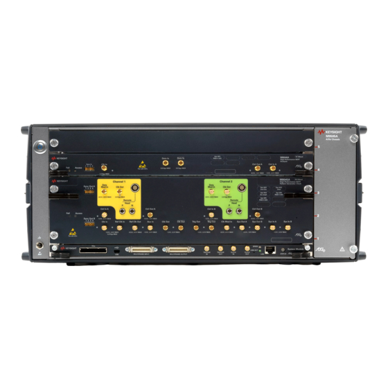
The small device on top of the M8040A in the connection diagram is the M8040's remote head, which is its output amplifier. ® Figure 1 MIPI M-PHY Frame Generator hardware setup for J-BERT M8040A Keysight MIPI M-PHY Frame Generator User Guide... - Page 11 26.5GHz, 2 pieces for each data lane. This configuration supports the Loopback and UniPro operating modes. The Keysight M8046A analyzer module can be used to do loopback testing with continuous patterns. However, it cannot be used to test bursts. With the M8040A it is also possible to test two receiver channels of the DUT simultaneously.
- Page 12 For more details, see Connecting to the Instruments on page 25. This setup can be used to perform transmitter tests using the Keysight scopeapp application. The DSGA (BIT-3000), see Figure 3, can be used alone to generate the...
- Page 13 Test Instrument Setup ® Figure 3 MIPI M-PHY Frame Generator hardware setup for BIT-3000 DSGA Keysight MIPI M-PHY Frame Generator User Guide...
-
Page 14: Setting Up The Instruments
Test Instrument Setup Setting Up the Instruments Before using the connection part of the MIPI M-PHY Frame Generator software, set up the test instruments and the DUT and establish the required connections between them. • Connect the instruments to the controller PC by LAN. - Page 15 Keysight MIPI M-PHY Frame Generator User Guide Installing and Updating the Software Software Update / 16 / 17 Software Installation The MIPI M-PHY Frame Generator software runs on the PC that controls ® the BERT. If it is already installed on the PC and is not to be updated,...
-
Page 16: Software Update
Generator software, please uninstall it from the PC during the installation of the new version when prompted by the setup program. You may choose whether to uninstall just the program files or the user data as well. Keysight MIPI M-PHY Frame Generator User Guide... -
Page 17: Software Installation
Then, click the Install button to install the software. After the installation the computer does not need to be rebooted. An icon named “MIPI M-PHY Frame Generator” will be added to the desktop. Keysight MIPI M-PHY Frame Generator User Guide... - Page 18 Software Installation and Update Keysight MIPI M-PHY Frame Generator User Guide...
- Page 19 Keysight MIPI M-PHY Frame Generator User Guide Starting and Registering the Software Starting Unregistered Software / 20 Starting Registered Software / 21 Start the software with a double-click of the left mouse button on the M-PHY Frame Generator (N5991) icon. Alternatively, start the application...
-
Page 20: Starting Unregistered Software
To obtain a valid license, use the BitifEye License Manager (BLM) portal https://licensing.bitifeye.com/, add the license to your PC and activate it. For detailed instructions on how to use the BLM, please refer to the manual BitifEye License Manager User Guide. Keysight MIPI M-PHY Frame Generator User Guide... -
Page 21: Starting Registered Software
Starting and Registering the Software Starting Registered Software If the software is already registered, it starts automatically. Proceed to Chapter 5, “Using the Software”. Keysight MIPI M-PHY Frame Generator User Guide... - Page 22 Starting and Registering the Software Keysight MIPI M-PHY Frame Generator User Guide...
- Page 23 Keysight MIPI M-PHY Frame Generator User Guide Using the Software General Features / 24 Connecting to the Instruments / 25 Disconnecting from the Instruments / 28 Signal Settings / 29 Using UniPro Scripts / 60 Once the software has been installed, the N5991 M-PHY Frame Generator icon will appear on the desktop.
-
Page 24: General Features
Clicking Copy to Clipboard copies details about the software version and the license to the clipboard, so that you can easily paste this information into an e-mail if you have to contact BitifEye with a query. Keysight MIPI M-PHY Frame Generator User Guide... -
Page 25: Connecting To The Instruments
Figure 5 MIPI M-PHY N5991 Frame Generator CONNECTION window for M8040A First choose the BERT (either M8040A from Keysight or BIT-3000 from BitifEye) using the Instrument dropdown menu, according to the setup you want to use (refer to Chapter 2, “Test Instrument Setup”). -
Page 26: J-Bert M8040A Mipi® M-Phy Generator
BIT-3000. See Figure 6. The Connection Diagram will indicate the connections needed. Specify the DSGA address using TCP/IP. Finally, click Connect to finish configuring the setup. Keysight MIPI M-PHY Frame Generator User Guide... - Page 27 Using the Software ® Figure 6 MIPI M-PHY N5991 Frame Generator CONNECTION window for BIT-3000 Keysight MIPI M-PHY Frame Generator User Guide...
-
Page 28: Disconnecting From The Instruments
When you want to change the configuration after running some tests, return to the Connection window by clicking first the CONNECTION button and then Disconnect. The message “Disconnection from instruments successful!” should appear in the log. Keysight MIPI M-PHY Frame Generator User Guide... -
Page 29: Signal Settings
White lettering on a blue background shows which tab is visible. Figure 8 shows an alternative arrangement of the tabs, where only one is visible at a time. Keysight MIPI M-PHY Frame Generator User Guide... - Page 30 Settings • View • Apply • Abort • Break • Restart • Reset DUT and seven tabs • Protocol • Pattern • Voltage Levels • Skew • Jitter • Data Rates • Analysis Keysight MIPI M-PHY Frame Generator User Guide...
-
Page 31: Settings Icon
It is also possible to reset the arrangement to the default one. With the menu point windows, you can disable or enable particular tabs by clicking on their names in the pop-up list (see Figure Keysight MIPI M-PHY Frame Generator User Guide... - Page 32 (see Figure 10). It can be docked back on to the others by dragging it back towards them, so that it turns into a tab again. Keysight MIPI M-PHY Frame Generator User Guide...
-
Page 33: Apply Icon
This means that the instrument does not step into the link training until manually forced to. This is achieved by clicking BREAK. The instrument moves on to the second block in the generator sequence. Keysight MIPI M-PHY Frame Generator User Guide... -
Page 34: Restart Icon
The function of the Reset DUT Icon is related to the connection configuration. If the Trigger Out of the DSGA is connected in the configuration, a Trigger Out signal is generated to reset the DUT. Keysight MIPI M-PHY Frame Generator User Guide... -
Page 35: Protocol Tab
Protocol Tab The Protocol Tab (see Figure 11) provides access to the M-PHY-specific settings that you can change. The values of the parameters will vary according to the DUT. Figure 11 Protocol Tab Keysight MIPI M-PHY Frame Generator User Guide... -
Page 36: Pattern Tab
For Fine, the duration of the Initial ADAPT sequence is calculated as = 650 * (ADAPT_length + 1). ADAPT ADAPT_length For Coarse, T = 650 * 2 , where ADAPT_length < 18. ADAPT Keysight MIPI M-PHY Frame Generator User Guide... - Page 37 “SQUELCH” entry in the data block definition (see Pattern Tab on page 40). • Squelch Pulse Width: This is the width of the DIFN pulse in the squelch data block. Keysight MIPI M-PHY Frame Generator User Guide...
- Page 38 Sync Pattern: D10.5 and D26.5 are the default sync symbols used for the sync pattern. The symbols with at least seven transitions inside the symbol (of nine possible transitions) are used for the sync sequence. Keysight MIPI M-PHY Frame Generator User Guide...
- Page 39 Connection window, the buttons Low speed analyzer (DSGA) and DSGA Trigger are set to ON. If it is enabled, a Trigger Out signal from the DSGA is generated to physically reset the DUT on starting the sequence. Keysight MIPI M-PHY Frame Generator User Guide...
- Page 40 Pattern Tab - Script Editor window The script editor allows you to edit the training sequences and patterns using a unified syntax. For details of this language, refer to the MIPI M-PHY Frame Generator Language Guide. Keysight MIPI M-PHY Frame Generator User Guide...
- Page 41 8b/10b; the remaining entries in the tool allow you to convert numbers between this and other systems instantly, in both directions. Figure 13 Pattern Tab - Pop-up list of conversions Keysight MIPI M-PHY Frame Generator User Guide...
- Page 42 If you mark part of the content of the Process Script or Post Process Script field and then right-click, a menu pops up that you can use to cut, copy or paste the marked part of the script. Keysight MIPI M-PHY Frame Generator User Guide...
- Page 43 15), in which the blocks are listed as data; you can see exactly what the data looks like (in hexadecimal notation) that will be sent to the instruments. Figure 15 Pattern Tab - Post Process Script window Keysight MIPI M-PHY Frame Generator User Guide...
-
Page 44: Voltage Levels Tab
Clock Settings • Termination: This is set as Unterminated for the clock channel. • Level Mode: The levels can be set either in terms of High Level/Low Level or in terms of Amplitude/Offset. Keysight MIPI M-PHY Frame Generator User Guide... - Page 45 FIR (Finite Impulse Response) Tap Coefficients is displayed as read-only values. Note that the values of De-Emphasis and Preshoot applied to the signal may differ slightly from what is expected, as a result of rounding errors. Keysight MIPI M-PHY Frame Generator User Guide...
- Page 46 Using the Software Figure 17 Voltage Levels Tab - Data0 channel Keysight MIPI M-PHY Frame Generator User Guide...
-
Page 47: Data Rates Tab
Figure 18 Data Rates Tab Parameters in the Data Rates Tab • Ref. Clock Frequency: Select from 19.2, 26, 38.4 and 52MHz for M8040A. For BIT-3000 only the first three are available. Keysight MIPI M-PHY Frame Generator User Guide... - Page 48 2 to give an applied data rate resembling Gear 1. Low Speed • PWM Data Rate: Set the nominal PWM data rate. Min: 3Mbit/s Default: 4.5Mbit/s Max: 9Mbit/s Keysight MIPI M-PHY Frame Generator User Guide...
- Page 49 Example: For a burst with 250 PWM bits and a '-10' (negative) speed, the variation period is 25 PWM bits. • PWM Bit Resolution: This read-only value gives the number of bits per PWM period. Keysight MIPI M-PHY Frame Generator User Guide...
-
Page 50: Skew Tab
Changes that you make in the Skew Tab are applied immediately. You do not have to click Apply. Figure 19 Skew Tab Keysight MIPI M-PHY Frame Generator User Guide... -
Page 51: Jitter Tab
Changes that you make in the Jitter Tab are applied immediately. You do not have to click Apply. Figure 20 Jitter Tab Keysight MIPI M-PHY Frame Generator User Guide... - Page 52 Amplitude: Set the amplitude of the jitter in unit intervals (UI) manually, by slider or by clicking the max, min or default button. • Amplitude (RMS) (only ST Random Jitter): Read only. The corresponding RMS jitter. Keysight MIPI M-PHY Frame Generator User Guide...
-
Page 53: Analysis Tab
Ensure that the Analysis Selector is set to Configuration. If the Low Speed Analyzer (DSGA) is not configured in the Connection window (that is, it is set to OFF), you can set parameters for the BER Analyzer in the Analysis Tab (see Figure 21). Keysight MIPI M-PHY Frame Generator User Guide... - Page 54 Transition Density: Set the transition density of the CDR. Min: 0% Default: 50% Max: 100% • Follow SYS Clock: If ON, the Analyzer Symbol Rate is a read-only parameter and depends on what you have chosen in the Data Rates tab. Keysight MIPI M-PHY Frame Generator User Guide...
- Page 55 Reset: This button sets the bit and error counters and the BER back to zero. • Bit Error Ratio: The ratio of the number of false or error bits to the total number of transmitted bits, that is, errors/bits. Keysight MIPI M-PHY Frame Generator User Guide...
- Page 56 Speed Analyzer (DSGA) is configured in the Connection window (that is, it is set to ON), you can set parameters for the DSGA Analyzer in the Analysis Tab (see Figure 23). Figure 23 Analysis Tab - Configuration, with Low Speed Analyzer Keysight MIPI M-PHY Frame Generator User Guide...
- Page 57 DUT. The Tx responses from the DUT will be configured to be sent back in PWM gear. The DUT responds back to the counters with the PACP packets, which will then be analyzed by the Analyzer of the DSGA. Keysight MIPI M-PHY Frame Generator User Guide...
- Page 58 (upper) output panel and the Frame Counter and Error Counter values will be updated. • Frames: Number of frames received by the DUT. • Errors: Number of frame errors detected. Keysight MIPI M-PHY Frame Generator User Guide...
-
Page 59: Global Outputs Switch
“1. Sleep”, so you know which block of the sequence has been reached. If the setup is running offline, “not available” appears in the parameter field. The Sequence State switch changes to ON automatically when you click the Apply Icon. Keysight MIPI M-PHY Frame Generator User Guide... -
Page 60: Using Unipro Scripts
• Output Sequence: Either set the path for the output sequence or keep the default one. • Generate Patterns: Click this button to generate the patterns once all the parameters have been set. Keysight MIPI M-PHY Frame Generator User Guide... - Page 61 DUT. • RxGear1A, 1B, …, 5A, 5B: The DUT will transmit the signal in HS in the selected Gear. • Rx Test Pattern: The pattern currently supported is CJTPAT. Keysight MIPI M-PHY Frame Generator User Guide...
- Page 62 Tx Equalization: Choose 0dB, 3.5dB or 6dB. The selected values are reflected only in sequences for Gear 3 and above, but if required the equalization block can be included in the configuration of Tx Gear 1 and Gear 2 sequences manually. Keysight MIPI M-PHY Frame Generator User Guide...
- Page 63 • Gap Length: The parameters in this section are used to specify the lengths of the different gaps that are used in the training sequence. • Gap Unit: The default unit is Symbols. Keysight MIPI M-PHY Frame Generator User Guide...
- Page 64 DIFP: Differential positive voltage. Min: 0s Default: 3.5ms Max: 10s • DIFN: Differential negative voltage. Min: 0s Default: 5ms Max: 10s • Sleep: Power-saving state between LS bursts. Min: 0s Default: 50 s Max: 10s Keysight MIPI M-PHY Frame Generator User Guide...
-
Page 65: Working In The Unipro Test Mode
UniProRx[HsGear][Mode][Amplitude][Channel].seq appears in the sequence field, then to the left of that field the actual sequence running may be given as UniProRxGear1ABurstLargeData0.seq according to the values of the parameters selected in the various tabs. Keysight MIPI M-PHY Frame Generator User Guide... - Page 66 Data Rates Tab [Mode] Cont, Burst Protocol Tab [Amplitude] Large, Small Protocol Tab [Channel] Data0, DataAll For Rx Test Mode (UniPro Script Generator): Protocol Tab; For Tx Test Mode (UniPro Script Generator): Pattern Tab Keysight MIPI M-PHY Frame Generator User Guide...
-
Page 67: Troubleshooting
Keysight MIPI M-PHY Frame Generator User Guide Troubleshooting Support Information / 68 / 69 Using Logs... -
Page 68: Support Information
You can find these by clicking ABOUT in the main Frame Generator window (see Figure 4). Clicking the Copy to Clipboard button copies these details to the clipboard, so that you can easily paste this information into your e-mail. Keysight MIPI M-PHY Frame Generator User Guide... -
Page 69: Using Logs
Software Installation and Update Using Logs Right click the Log panel, select Show Log File to view the logs and investigate the root cause of an issue. Keysight MIPI M-PHY Frame Generator User Guide... - Page 70 Software Installation and Update Keysight MIPI M-PHY Frame Generator User Guide...
-
Page 71: Appendix A: Acronyms And Abbreviations
Keysight MIPI M-PHY Frame Generator User Guide Appendix A: Acronyms and Abbreviations This Appendix contains a list of acronyms and abbreviations used in the Keysight MIPI M-PHY Frame Generator User Guide. - Page 72 ® MIPI Mobile Industry Processor Interface Marker Zero M-PHY A high speed data communications physical layer protocol standard Personal Computer PACP PHY Adapter Control Protocol Pulse-Width Modulation Root Mean Squared Receiver Symbol Interval Keysight MIPI M-PHY Frame Generator User Guide...
- Page 73 Duration of ADAPT Sequence ADAPT Transmission Control Protocol Duration of HS SYNC Sequence SYNC Transition Time Converter Transmitter Universal Flash Storage Unit Interval UniPro Unified Protocol VISA Virtual Instrument System Architecture Terminated Voltage term Keysight MIPI M-PHY Frame Generator User Guide...
- Page 74 Software Installation and Update Keysight MIPI M-PHY Frame Generator User Guide...
- Page 75 Keysight MIPI M-PHY Frame Generator User Guide...
- Page 76 This information is subject to change without notice. © Keysight Technologies 2021 Edition 1.0, November 2021 www.keysight.com...
Need help?
Do you have a question about the MIPI M-PHY and is the answer not in the manual?
Questions and answers