Table of Contents
Advertisement
Advertisement
Table of Contents

Related Manuals for Keysight M8190A


Summary of Contents for Keysight M8190A
- Page 1 Keysight M8190A Arbitrary Waveform Generator User’s Guide...
- Page 2 OR OF ANY INFORMATION or loss of important data. Do not CONTAINED HEREIN. SHOULD The foregoing warranty shall not KEYSIGHT AND THE USER HAVE A proceed beyond a CAUTION apply to defects resulting from SEPARATE WRITTEN AGREEMENT notice until the indicated...
-
Page 3: Safety Summary
Verify that all safety precautions are taken including those defined for the mainframe. Line Power The Keysight M8190A operates when installed in an Keysight AXIe mainframe. Requirements Do Not Operate in an Do not operate the instrument in the presence of flammable gases or fumes. -
Page 4: Safety Symbols
Product category: With reference to the equipment types in the WEEE Directive Annexure I, this product is classed as a “Monitoring and Control instrumentation” product. Do not dispose in domestic household waste. To return unwanted products, contact your local Keysight office, or see http://about.keysight.com/en/companyinfo/environment/takeback.shtml for more information. -
Page 5: Table Of Contents
1.5.1 Block Diagram 1.5.2 NRZ / DNRZ / Doublet 26 1.5.3 Delay Adjust 29 Installing Licenses M8190A User Interface Introduction Launching the M8190A Soft Front Panel M8190A User Interface Overview 2.3.1 Title Bar 2.3.2 Status Bar 2.3.3 Menu Bar 2.3.4... - Page 6 Sequencer Execution Flow Sequencer Modes 3.8.1 Arbitrary Mode 3.8.2 Sequence Mode 3.8.3 Scenario Mode Dynamic Sequencing 121 3.9.1 Dynamic Continuous 122 3.9.2 Dynamic Triggered 3.10 Idle Command Segments 3.11 Limitations 125 3.11.1 Segment Length and Linear Playtime M8190A User’s Guide...
- Page 7 Pause Between Multiple Marked Samples 161 6.2.2 Sample Marker in Looped Segments 6.2.3 Sample Marker in Segments which are Addressed Offset Based Sync Markers Low Phase Noise Operation Introduction Block Diagram Operating in the Low Phase Noise Mode 165 M8190A User’s Guide...
- Page 8 Voltage Status Subsystem 8.7.6 Frequency Status Subsystem 8.7.7 Sequence Status Subsystem 8.7.8 Connection Status Subsystem 195 8.7.9 Run Status Subsystem 195 :ARM/TRIGger Subsystem 8.8.1 :ABORt[1|2] 196 8.8.2 :ARM[:SEQuence][:STARt][:LAYer]:DELay[1|2][?] <delay>|MINimum|MAXimum 8.8.3 :ARM[:SEQuence][:STARt][:LAYer]:CDELay[1|2][?] <coarse_delay>|MINimum|MAXimum 8.8.4 :ARM[:SEQuence][:STARt][:LAYer]:RNOisefloor[1|2][?] OFF|ON|0|1 8.8.5 :INITiate:CONTinuous[1|2]:ENABle[?] SELF|ARMed 199 M8190A User’s Guide...
- Page 9 OFF|ON|0|1 8.9.5 :TRIGger[:SEQuence][:STARt]:ADVance[1|2][:IMMediate] 8.10 :FORMat Subsystem 215 8.10.1 :FORMat:BORDer NORMal|SWAPped 8.11 :INSTrument Subsystem 8.11.1 :INSTrument:COUPle:STATe[1|2][?] OFF|ON|0|1 8.11.2 :INSTrument:SLOT[:NUMBer]? 217 8.11.3 :INSTrument:IDENtify [<seconds>] 8.11.4 :INSTrument:IDENtify:STOP 8.11.5 :INSTrument:MMODule:CONFig? 8.11.6 :INSTrument:MMODule:MODE? 8.12 :MMEMory Subsystem 8.12.1 :MMEMory:CATalog? [<directory_name>] 8.12.2 :MMEMory:CDIRectory [<directory_name>] M8190A User’s Guide...
- Page 10 Reference Oscillator Commands 8.15.1 [:SOURce]:ROSCillator:SOURce[?] EXTernal|AXI|INTernal 8.15.2 [:SOURce]:ROSCillator:SOURce:CHECk? EXTernal|AXI|INTernal 237 8.15.3 [:SOURce]:ROSCillator:FREQuency[?] <frequency>|MINimum|MAXimum 8.16 :DAC|DC|AC Subsystem 8.16.1 [:SOURce]:DAC|DC|AC[1|2]:FORMat[?] RZ|DNRZ|NRZ|DOUBlet 8.16.2 Voltage Ranges 8.16.3 [:SOURce]:DAC|DC|AC[1|2]:VOLTage[:LEVel][:IMMediate] :AMPLitude[?] <level> 239 8.16.4 [:SOURce]:DAC|DC[1|2]:VOLTage[:LEVel][:IMMediate]:OFFSet[?] <level> 8.16.5 [:SOURce]:DAC|DC[1|2]:VOLTage[:LEVel][:IMMediate]:HIGH[?] <level> 8.16.6 [:SOURce]:DAC|DC[1|2]:VOLTage[:LEVel][:IMMediate]:LOW[?] <level> 8.16.7 [:SOURce]:DC[1|2]:VOLTage[:LEVel][:IMMediate]:TERMination[?] <level> M8190A User’s Guide...
- Page 11 [:SOURce]:SEQuence[1|2]:NAME[?] <sequence_id>, <name> 8.20.10 [:SOURce]:SEQuence[1|2]:COMMent[?] <sequence_id>,<comment> 8.21 :STABle Subsystem 259 8.21.1 Generating arbitrary waveforms in dynamic mode 259 8.21.2 Generating sequences in non-dynamic mode 8.21.3 Generating sequences in dynamic mode 259 8.21.4 Generating scenarios 260 8.21.5 [:SOURce]:STABle[1|2]:RESet 260 M8190A User’s Guide...
- Page 12 |INTX3|INTX12|INTX24|INTX48 279 8.22.12 :TRACe[1|2][:DATA][?] <segment_id>, <offset>,(<length>|<block>|<numeric_values>) 8.22.13 :TRACe[1|2]:IQIMport <segment_id>,<file_name>, TXT|TXT14|BIN|IQBIN| BIN6030|BIN5110|LICensed|MAT89600|DSA90000|CSV,IONLy| QONLy|BOTH,ON|OFF|1|0,[,ALENgth|FILL|[,<init_valueI> [,<init_valueQ> [,<ignore_header_parameters>]] 282 8.22.14 :TRACe[1|2]:IMPort <segment_id>,<file_name>, TXT|TXT14|TXTD|BIN|BIN6030 [,ALENgth|FILL|[,<dac_value>]] 8.22.15 :TRACe[1|2]:DELete <segment_id> 8.22.16 :TRACe[1|2]:DELete:ALL 8.22.17 :TRACe[1|2]:CATalog? 8.22.18 :TRACe[1|2]:FREE? 8.22.19 :TRACe[1|2]:SELect[?] <segment_id> 8.22.20 :TRACe[1|2]:NAME[?] <segment_id>,<name> 8.22.21 :TRACe[1|2]:COMMent[?] <segment_id>,<comment> M8190A User’s Guide...
- Page 13 [:SOURce]:ACTion[1|2]:DEFine[:NEW]? 307 8.27.2 [:SOURce]:ACTion[1|2]:APPend <action_sequence_index>,<action>[,<value> [,<value>]] 8.27.3 [:SOURce]:ACTion[1|2]:DELete <action_sequence_id> 8.27.4 [:SOURce]:ACTion[1|2]:DELete:ALL Example Programs and Files Characteristics 10.1 Performance Specification 10.2 General Appendix 11.1 Resampling Algorithms for Waveform Import 11.1.1 Resampling Requirements 11.1.2 Resampling Methodology 11.1.3 Resampling Modes M8190A User’s Guide...
- Page 15 0.75 GSa = 768 MSa = 805,306,368 Sa IQ sample pair arbitrary waveform memory per channel with Option -02G in DUC mode. I.e. with Option -02G and Option -DUC, the M8190A offers 768 MSa I data and 768 MSa Q data per channel ...
- Page 16 Introduction Supporting Operating The Keysight M8190A supports the following operating systems: System Windows 10 (32 bit or 64 bit) Windows 8.1 (32 bit or 64 bit) Windows 8 (32 bit or 64 bit) Windows 7 (32 bit or 64 bit)
-
Page 17: Introduction
Edition 11.0 (October, 2015) Edition 12.0 of the User’s Guide describes the functionality of firmware version V5.3. Edition 12.0 (May, 2017) Edition 13.0 of the User’s Guide describes the functionality of firmware version V5.3. Edition 13.0 (October, 2017) M8190A User’s Guide... -
Page 18: Options
Introduction 1.2 Options The AWG has a modular product structure and requires AXIe chassis. Table 1-1: Options provided by M8190A M8190A Option Available as SW Comment upgrade? 1 channel -001 Must order either -001 or -002 2 channel -002 14 bit / 8 GSa/s... - Page 19 Introduction Option -001, -002 With this option the number of channels is selected. The M8190A is available as a one channel (-001) or 2 channel (-002) instrument. There is no upgrade possible from option -001 to option -002. Option -14B, -12G These options define the resolution and the maximum sample rate of the M8190A: ...
- Page 20 Introduction In DUC mode, the DAC always operates with 14 bit resolution. Option -12G is installed and option -14B is not installed=> The M8190A operates with 14 bit resolution, if DUC mode is selected. Option -12G is not installed and option -14B is installed=> The M8190A operates with 14 bit resolution, if DUC mode is selected.
-
Page 21: The Front Panel Of The Two Channel Instrument
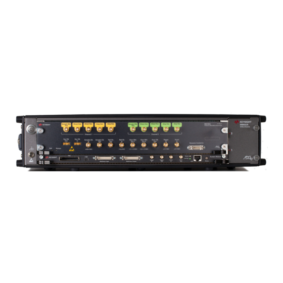
Introduction 1.3 The Front Panel of the Two Channel Instrument The Front Panel of the two channel M8190A is shown in the figure below. Figure 1-1: Front Panel of M8190A (2 Channels) Inputs/Outputs The inputs and outputs of the instrument are available at the front panel: ... - Page 22 Introduction The Trigger Input (TRIGGER IN) has a combined functionality as Trigger or Gate and is used to start the M8190A by an external signal. This input is defined in detail in the chapter Sequencing. The Event Input (EVENT IN) is used to e.g. step through segments or scenarios by an external signals.
-
Page 23: The Front Panel Of The One Channel Instrument
There is one SMA connector labeled ‘Do not connect’. This connector is for future use. Status LED The functionality of the LED is identical with the 2 channel M8190A. Refer to the section Status LED for a description of the status LED. -
Page 24: Modes Of Operation
1.5.1 Block Diagram The drawing below shows a block diagram of the instrument. Figure 1-3: M8190A Block Diagram The level of detail is chosen to provide a general high level understanding of how the instrument is working. Therefore, not all of ports are shown in the above diagram. - Page 25 Sync Clock. This allows providing an exact output delay from the inputs to the DAC output for all cases where triggers and events are generated based on the Sync Clock output and where the corresponding setup and hold time conditions are met. M8190A User’s Guide...
-
Page 26: Nrz / Dnrz / Doublet
RZ (Return to Zero) It is not specified but available as over-programming. For more details on the DAC format modes, refer to the section “Dual-Core DAC Architectures” in the Fundamentals of Arbitrary Waveform Generation Reference Guide (Manual Part No. M8190-91050). M8190A User’s Guide... - Page 27 DNRZ: DAC A and B send same value Doublet: DAC A sends +Value, DAC B RZ (not specified but available as over sends –Value programming): DAC A sends value, DAC B fixed value Figure 1-4: DAC Format Modes M8190A User’s Guide...
- Page 28 Best signal performance in 1st Nyquist region For time domain applications, less ripple at 2 f , more sample distortions than DNRZ Doublet More output power and flatter frequency response in 2nd Nyquist region limited to f > 1 GSa/s sample M8190A User’s Guide...
-
Page 29: Delay Adjust
Sample Clock Out, Sync Marker Out1, Sync Marker Out2, Direct Out2 (or Amp Out2, if selected), Trigger / Gate Input, Event Input Modifying the variable delay of one channel always affects the delay of the Analog Output AND the Sample Marker of that channel. M8190A User’s Guide... -
Page 30: Installing Licenses
On Windows-based systems, you can install the license by copying the license file into the license directory C:\Program Files\Keysight\licensing. Once the licenses are installed, you can use the Keysight License Manager to view all licenses for the local system as depicted in the following figure. M8190A User’s Guide... - Page 31 Introduction Figure 1-6: Using Keysight License Manager to view installed licenses Licenses for instrument options are transferred to the M8190A module. They are later no longer visible in the Keysight License Manager. M8190A User’s Guide...
-
Page 33: M8190A User Interface
Import Waveform Tab / 72 2.13 Sequence Table Tab / 78 2.15 Status/Control Tab / 84 2.16 Correction File Format / 87 2.17 M8190 Soft Front Panel and M8190 Firmware / 88 2.1 Introduction This chapter describes the M8190A Soft Front Panel. -
Page 34: Launching The M8190A Soft Front Panel
2.2 Launching the M8190A Soft Front Panel There are three ways to launch the M8190A Soft Front Panel: Select Start > All Programs > Keysight M8190 > Keysight M8190 Soft Front Panel From the Keysight Connection Expert select the discovered M8190A module, press the right mouse key to open the context menu and select “Send... - Page 35 The instrument selection dialog shows the addresses of the discovered M8190A modules. Select a module from the list and press “Connect”. If no M8190A module is connected to your PC, you can check “Simulation Mode” to simulate an M8190A module.
-
Page 36: M8190A User Interface Overview
M8190A User Interface 2.3 M8190A User Interface Overview The M8190A user interface includes the following GUI items: Title Bar Menu Bar Status Bar Tabs (Clock, Output, Aux, Standard Waveform, Multi-Tone, Complex Modulation, Import Waveform, Sequence Table, and Status/Control) The detailed information on these GUI items is described in the sections that follow. -
Page 37: File Menu
M8190A User Interface 2.3.3.1 File Menu The File menu includes the following selections: File – Connect… Opens the instrument selection dialog. File – Save Configuration As… Saves configuration as a text file. File – Load Configuration… Load the previously saved configuration file. -
Page 38: Clock/Output/Aux/Standard Waveform/ Multi-Tone/Complex Modulation/Import Waveform/ Sequence Table /Status/Control Tabs
2.3.4 Clock/Output/Aux/Standard Waveform/ Multi-Tone/Complex Modulation/Import Waveform/ Sequence Table /Status/Control Tabs These tabs are used to configure the most important parameters of the M8190A module. They are described in detail in the sections that follow. 2.3.5 Numeric Control Usage The numeric control is used to adjust the value and units. - Page 39 M8190A User Interface The numeric controls can be used in the following ways: Use the up/down arrows to change the value. The control automatically stops at the maximum/minimum allowed value. You can increase or decrease the value starting at a specific portion of the value.
-
Page 40: Driver Call Log
M8190A User Interface 2.4 Driver Call Log Use this window to inspect the sequence of IVI driver calls and SCPI commands used to configure the M8190A module. Figure 2-5: Driver Call Log Window It has the following buttons: Save…... -
Page 41: Errors List Window
M8190A User Interface 2.5 Errors List Window Use this window to view errors, warnings, and information. Figure 2-6: Errors List Window It has the following controls, signs, and columns: Open On Error Select this check box to automatically open the errors list window whenever an error occurs. -
Page 42: Clock Tab
M8190A User Interface 2.6 Clock Tab Use this tab to configure the sample clock and the reference clock of the M8190A module. It contains switches for internal/external sample clock selection and input fields to configure the relevant frequencies. Figure 2-7: Clock Tab... - Page 43 M8190A User Interface Reference clock selection switch This switch selects between the different reference clock sources. Internal: Reference generated by an internal oscillator inside the M8190A module Internal Backplane 100 MHz: Reference from AXI Backplane of the AXIe chassis ...
-
Page 44: Output Tab
M8190A User Interface 2.7 Output Tab Use this tab to configure the outputs (Channel 1 and Channel 2) of the M8190A module. Figure 2-8: Output Tab M8190A User’s Guide... - Page 45 M8190A User Interface The two channels have the following input fields. Mode Selects the waveform output modes. Available selections depend on the selection made by the direct/interpolated radio buttons. Direct mode: 12 bit, 14 bit. Interpolated mode: INTX3/12/24/48. ...
- Page 46 M8190A User Interface Output path selection switch Selects among the three output paths. Depending on this setting, the input fields for offset and termination voltage are applicable or not. DAC: Direct DAC output (optimized for best SFDR & HD, differential output) ...
- Page 47 M8190A User Interface VTerm Specifies the termination voltage when the DC output path is selected. Fine Delay Specifies the fine delay portion of the variable delay (see available Range). Coarse Delay Specifies the coarse delay portion of the variable delay.
-
Page 48: Aux Tab
M8190A User Interface 2.8 Aux Tab Use this tab to configure the external trigger and event inputs and the marker outputs of the M8190A module. Figure 2-9: Aux Tab M8190A User’s Guide... - Page 49 M8190A User Interface This tab has the following input fields. Threshold for trigger and event input Sets threshold level. Polarity for trigger and event input Sets the polarity for the input. Positive – rising edge Negative – falling edge Either - both ...
- Page 50 M8190A User Interface Advancement Event hardware input switch Enable or disable the advancement event hardware input for channel 1 and channel 2. Advance Event works according to the advancement mode (Auto, Conditional, Repeat, Single) selected. The advancement event is used to advance within a scenario or sequence.
-
Page 51: Standard Waveform Tab
M8190A User Interface 2.9 Standard Waveform Tab Use this tab to create a variety of standard waveform types. It provides the controls which allow the complete definition of signal generation parameters for the following waveform shapes: Sinusoidal Square with linear transitions ... - Page 52 M8190A User Interface This tab has the following controls: Waveform Destination Section Generate I/Q Data Always checked while in up-converter modes. While in direct mode, it will assign the I (In-phase) component to Channel 1 and the Q (Quadrature) component to Channel 2.
- Page 53 M8190A User Interface Basic Waveform Parameters Section Waveform Type: The following waveform types are available: Sine: Sinusoidal waveform. Frequency and Initial Phase parameters can be defined for this waveform type. If the Generate I/Q checkbox is checked, two sinewaves with a 90º phase difference will be assigned to the I and Q components.
- Page 54 M8190A User Interface Symmetry For both triangular and sinc waveforms, it marks the location as a percentage of the positive highest peak within a period of the basic signal. Sinc Length The number of zero crossings in a single period for the sinc waveform type.
- Page 55 M8190A User Interface Waveform Length The length in samples of the resulting segment. It may be set within acceptable limits and it may be calculated automatically to properly implement other signal and instrument parameters such as sampling rate. ...
- Page 56 M8190A User Interface Preview Section Waveform Preview Toolbar The waveform preview toolbar includes the icons to preview the waveform. The following icons are available: Uses the mouse to control the marker. The respective position of marker at X and Y axis are displayed on the top of waveform.
-
Page 57: Multi-Tone Tab
M8190A User Interface 2.10 Multi-Tone Tab Use this tab to create signals made-up of multiple tones, either equally or arbitrarily spaced. It also allows for the definition of a frequency interval without tones (or notch) for NPR (Noise Power Ratio) testing. Amplitudes and phases of the individual tones can be corrected through correction factor files defined by the user. - Page 58 This checkbox activates the application of the correction factors. For more details about corrections and how the correction factors in a file can be generated, refer to M8190A Reference Guide. You can also refer to the Example Programs and Files section which provides an example to create corrections using the VSA.
- Page 59 M8190A User Interface Additional Waveform Parameters Section Waveform Length It is indicator only. The length is in samples of the resulting segment. Max. Wfm. Length Maximum waveform length must be used to force the resulting waveform to be shorter or equal to the limit set by the user.
- Page 60 M8190A User Interface Preview Section Multi-Tone Preview Toolbar The waveform preview toolbar includes the icons that provide different functionality to preview the waveform. For details, see Preview Section Waveform Preview ToolbarPreview Toolbar. Compilation and Panel Control Section Save To File…...
- Page 61 M8190A User Interface Notch Parameters Section Notch Active This check box activates or deactivates the generation of a notch in the equally spaced multi-tone signal. Start Tone It is the index of the first tone to be removed in a notch. Acceptable indexes start with 1.
- Page 62 M8190A User Interface Figure 2-12: Multi-Tone Tab, Arbitrary Tone Distribution M8190A User’s Guide...
-
Page 63: Complex Modulation Tab
M8190A User Interface 2.11 Complex Modulation Tab Use this tab to create baseband and IF/RF digitally modulated signals. User-defined corrections may be applied to signals to compensate for (or emulate) instrument, interconnections and channel linear distortions. The complex modulation tab allows you to generate signals for both direct conversion and external/internal up-converter (IQ) modes. - Page 64 M8190A User Interface Figure 2-13: Complex Modulation Only relevant parameters and edition fields are shown in the GUI at any time depending on the selected generation mode (Direct/Up-converter) and modulation scheme. Waveform Destination Section Generate Baseband Data It is always seleced while in up-converter modes. If checked while in direct mode, it will assign the I (In-phase) component to Channel 1 and the Q (Quadrature) component to Channel 2.
- Page 65 M8190A User Interface Channel Independent checkboxes allow the definition of waveforms for Channel 1, Channel 2, or both. One of the boxes will be always checked and checking both is only possible when both channels are coupled (see Channel Coupling control in Clock Tab).
- Page 66 M8190A User Interface Alpha / BT The meaning and labeling of this edition field depends on the selected baseband filter. For “Nyquist” filters (Raised Cosine and Square Root of Raised Cosine) it is the ‘Alpha’ parameter (or roll-off factor) of the filter. For Gaussian filters it is the BT (Bandwidth/symbol period product) parameter.
- Page 67 M8190A User Interface Scaling Section DAC Max Waveforms may occupy a limited range of the DAC’s full scale. This parameter sets the maximum level. If set to a lower level than DAC Min, this will be automatically set to the same level. Acceptable range for this parameter is -1/+1, being the full dynamic range of the instrument’s DAC.
- Page 68 M8190A User Interface Custom Modulation File Format A custom modulation file is an ASCII delimited file including all the information required to define a single carrier modulated signal based in quadrature (IQ) modulation. The file must be composed of a header including a series of lines with identifiers and parameters, and a list of numerical correction factors.
- Page 69 M8190A User Interface The following example illustrates a simple example of a 3 bit per symbol QAM8 modulation with a particular constellation. #3 // MyModulationFile // Inner symbols 2.0, 0.0 0.0, -2.0 -2.0, 0.0 0.0, 2.0 // Outer symbols 3.0, 3.0 -3.0, 3.0...
- Page 70 M8190A User Interface The following example illustrates another possible use of custom modulation to define a distorted constellation. In this particular case, a O-QPSK modulation with a quadrature error (non-perpendicular I and Q axis) is defined: Offset, yes 1.05, 1.05 -0.95, 0.95...
- Page 71 M8190A User Interface The following is a more complex example: Offset, no Rotation, 10.0 RotMODE, cont 1.0, 0.0 2.0, 0.0 0.0 ,1.0 0.0, 2.0 -1.0, 0.0 -2.0, 0.0 0.0, -1.0 0.0 ,-2.0 The above file is composed of a header with relevant information. In this particular case, the file contains 8 (2 ) IQ pairs.
-
Page 72: Import Waveform Tab
2.12 Import Waveform Tab Use this tab to perform the functions such as importing, scaling, and resampling waveform files in a variety of formats for their generation by the M8190A arbitrary waveform generator. It provides the controls which allow the complete definition of... - Page 73 It must be checked to preserve the spectrum shape and the IQ axis assignment when the M8190A’ DAC is working in Doublet Mode and the desired signal sits in the second Nyquist band.
- Page 74 M8190A User Interface Data Columns It shows the internal organization of the file regarding waveforms. It can show from one column (Y1) up to 4 (Y1, Y2, Y3*, Y4*). Although files with more than 2 columns are reported correctly, only the first two columns (Y1, Y2) are imported and processed.
- Page 75 M8190A User Interface Output_SR: The user-defined output sampling rate will be used to calculate the best value for the output record length being a multiple of the granularity for the current DAC mode according to the time window of the input signal.
- Page 76 M8190A User Interface Source Sample Rate The speed at which samples in the input waveform are sampled. It can be set by typing a valid value unless the "Use As Source Sample Rate" checkbox is checked. In this particular case, the sampling rate information contained in the input waveform file will be always used.
- Page 77 M8190A User Interface Preview Section Waveform Preview Toolbar The waveform preview toolbar includes the icons which provides different functionality to preview the waveform. For details, see Preview Section Waveform Preview Toolbar. Show Next Waveform Preview This checkbox affects the behavior of the preview for the next waveform.
-
Page 78: Sequence Table Tab
M8190A User Interface 2.13 Sequence Table Tab Use this tab to create a sequence with one or more sequence entries. The characteristics of a sequence depend on the parameters’ values of the constituent entries. This tab allows to create, configure, and send new sequence configuration to the instrument and also to extract the existing one. - Page 79 M8190A User Interface Config (Configuation): A configuration entry is like normal data entry connected to sample data from the waveform memory but no segment loop count is available. Each configuration entry has a link to an entry of the Action Table and can initiate the execution of the corresponding action while playing the associated sample data.
- Page 80 M8190A User Interface New seq (New Sequence) Select the check box to start a new sequence. Total number of sequences are displayed by the counter “Sequence count.” Seq. Loop (Sequence Loop) Specifies the sequence loop count (number of times the selected sequence is to be repeated).
- Page 81 M8190A User Interface will be two columns for idle samples i.e. Idle Samp. I and Idle Samp. Q. Action ID Allows selection of an action ID from the available list for configuration entries only. The list displays the action IDs created in Action Table.
- Page 82 M8190A User Interface Action The following actions and their corresponding parameters can be added to the action IDs. PhaseOffset This action allows setting an offset to the current phase. The phase offset is a constant value added to the actual phase. It does not affect the NCO counter itself.
- Page 83 M8190A User Interface (Delete data) Click this icon to delete selected frequency rows. Amplitude Table # (Amplitude ID) Whenever a new amplitude row is created, it is automatically allocated a numeric ID termed as #. First amplitude row has the # value as 1, second as 2, and so on.
-
Page 84: Status/Control Tab
M8190A User Interface 2.15 Status/Control Tab This tab displays the most important status information of the M8190A module. Use this tab to start and stop signal generation and to send software triggers and events to the module. Figure 2-16: Status/Control Tab... - Page 85 M8190A User Interface This tab has the following controls. Sequencer Modes Arbitrary – Generate arbitrary waveform segments. STSequence – Generate sequences of segments. STSScenario – Generate scenarios (sequences of sequences). Arm mode Armed – Signal generation starts when an “enable” is received.
- Page 86 M8190A User Interface Valid Bits Selects the bit width of the dynamic control port. AllBits – The complete width of 19 bits is used for segment or sequence selection. LowerBits – The 13 lowest bits are used for segment or sequence selection. The upper 6 bits are set to 0.
-
Page 87: Correction File Format
Amp1(Fi), Phase1(Fi), Amp2(Fi), Phase2(Fi) sets. In particular, this format is compatible with adaptive equalizer files exported in comma-separated value (CSV) format from the Keysight 89600 VSA software package. These files reflect the channel response corrected by the equalizer so they should be applied through the selection of the ‘Channel_Response’... -
Page 88: M8190 Soft Front Panel And M8190 Firmware
M8190A User Interface This is an example for a two-channel correction file: ChannelNum, 2 InputBlockSize, 1024 XStart, 1.0E+09 XDelta, 1.0E+06 YUnit, lin 0.987, -0.2343, 0.976, -0.1827 0.995, 0.5674, 0.975, -0.1645 … … 1.269, -0.765, 1.190, -0.5632 The above files are composed of a header with relevant information. In these particular cases, the files contain 1024 linear correction factors spaced by 1 MHz and starting at 1GHz. -
Page 89: Introduction
Keysight M8190A – Arbitrary Waveform Generator User’s Guide Sequencing Introduction / 89 Sequencing Hierarchy / 91 Trigger Modes / 92 Arm Mode / 93 Advancement Modes / 94 Sequencer Controls / 95 Sequencer Execution Flow / 104 Sequencer Modes / 105... -
Page 90: Sequence Table
Within the sequence, a loop from address 9 to 6 is executed for a number of times, specified by loop counter values. It is possible to access the same sample data from different sequence vectors. In this example, waveform A is accessed from sequence vector 5 and 8. M8190A User’s Guide... -
Page 91: Sequencer Granularity
Multiple segments can be combined to a sequence. A sequence can be executed continuously or for a specified number of times. Sequence Start Segment 1 Segment 2 Segment 3 Trigger Repeat Count 1 Repeat Count 2 Repeat Count 3 Sequence Repeat Count (continuously or “n” times) Figure 3-2: Sequence M8190A User’s Guide... -
Page 92: Trigger Modes
Every trigger that occurs before the currently running segment/sequence/scenario has completed, is ignored. Alternatively, after having received a trigger, a waveform can also be played infinitely. See Sequencer Modes for more details. M8190A User’s Guide... -
Page 93: Gated
Triggered and Gated. Therefore in these cases the described behavior is not available and Armed is treated like Self Armed with an additional enable flag as start condition. M8190A User’s Guide... -
Page 94: Advancement Modes
After having executed all loops the sequencer stops and plays the last value of the current element. After having received the advancement event, the sequencer starts playing the next element. When receiving the advancement event before having played all repetitions, all repetitions will be played before moving to the next element. M8190A User’s Guide... -
Page 95: Single
3.6.1.1 TRIGGER/EVENT The M8190A accepts a wide range of external trigger signal levels to easily adapt to a measurement setup. The input threshold is user configurable along with the polarity or whether rising, falling or both edges are to be taken into account. The TRIGGER and EVENT input signals are clocked internally with the SYNC clock. - Page 96 The data is latched with the rising edge of the Load signal. DYNAMIC CONTROL IN Connector Description: Receptacle, Mini D Number of Contacts: 20 Manufacturer: 3M Part Number: 10220-0210EC Position 2 Position1 Last Position Figure 3-4: DYNAMIC CONTROL IN connector M8190A User’s Guide...
- Page 97 A rising edge on the Load signal latches the data present at the Data_In pins into the respective internal registers. If the Data_Select pin is low the loaded sequencer index is passed to the sequencer for execution. M8190A User’s Guide...
- Page 98 In 13 bit mode only the lower part of the sequencer entry address is modified. Data_Select can be left unconnected (low) in this mode. Only 8 k entries can be addressed in 13 bit mode vs. 512 k entries in 19 bit mode. M8190A User’s Guide...
- Page 99 Don’t care Addr 12…0 Data_Select Don’t care Data_Valid Hold Hold Load Figure 3-6: 19 Bit Mode Timing in both cases: = 5 ns Setup = 0 ns Hold = 7 SYNC clock cycles Load Maximum update rate: 1MHz M8190A User’s Guide...
-
Page 100: Logical Functions
When receiving an advancement event while executing a conditional segment, the advancement event is stored until reaching the end of the segment where the advancement is used. Then the stored advancement event is cleared and the instrument is able to receive the next one. M8190A User’s Guide... -
Page 101: Internal Trigger Generator
The run input is a software button or command, which switches the instrument from programming mode to run mode. 3.6.3 Internal Trigger Generator The M8190A provides a configurable internal trigger generator that allows for generation of a periodic trigger signal that is frequency locked to the clock of the sequencer engine. - Page 102 The software controls are logically ored with the external input or in case of the dynamic control, the software controls have precedence unless the hardware inputs are explicitly disabled using the commands. The figure below shows the logical input connectivity options provided by the M8190A for the TRIGGER and EVENT inputs. M8190A User’s Guide...
- Page 103 Sequencing Both_edge _detect Edge_ hw_disable detect Trigger/ Gate trigger_sw triggen_select Trigger Generator hw_disable Edge_ Event_trggen_select detect Advance Event_in event_sw Both_edge _detect event_select evnt_bedge_select hw_disable Enable enable_sw enable_select Figure 3-7: Logical input connectivity options provided by M8190A M8190A User’s Guide...
-
Page 104: Sequencer Execution Flow
Dependent from the selected trigger mode, the behavior in Armed mode is different. In trigger mode Continuous, the enable signal is used to control the execution of the first segment or sequence. In trigger mode Gated or Triggered, the enable is used as an additional start input. M8190A User’s Guide... -
Page 105: Arbitrary Mode
So the currently running segment/sequence or scenario is not completed before stopping. 3.8.1 Arbitrary Mode In Arbitrary Mode, a single segment is played. Segment Loop Count=4 Figure 3-9: Segment M8190A User’s Guide... - Page 106 Conditional: The segment is played infinitely after receiving a trigger. After being stopped (See SCPI command :ABORt[1|2]) the offset value is played. Offset Trigger Last Offset Value Trigger Stop (Abort) Figure 3-11: Segment Advance = Auto M8190A User’s Guide...
- Page 107 Adv Event Adv Event Trigger Last Last Last Offset Value Value Value Adv Event Adv Event Adv Event Stop Trigger (Abort) Figure 3-13: Segment Advance = Single Offset Offset Stop Trigger (Abort) Figure 3-14: Segment Advance = Conditional M8190A User’s Guide...
- Page 108 Later, changes of this signal are ignored. Trigger Mode Continuous Offset Offset Stop Enable (Abort) Figure 3-16: Trigger Mode Continuous Trigger Mode Triggered Last Offset Value Trigger Trigger Enable Figure 3-17: Trigger Mode Triggered M8190A User’s Guide...
- Page 109 Sequencing Trigger Mode Gated Last Offset Value Gate Enable Gate Gate Figure 3-18: Trigger Mode Gated M8190A User’s Guide...
-
Page 110: Sequence Mode
3.8.2.1 Self Armed Trigger Mode After programming, the sequence is started automatically and played infinitely. Continuous The following segment advancement modes are available: Auto Conditional (Advancement Event) Repeated (Advancement Event) Single (Advancement Event) M8190A User’s Guide... - Page 111 Conditional: The sequence is played infinitely after receiving a trigger. After being stopped (See SCPI command :ABORt[1|2]) the offset value is played. The following segment advancement modes are available: Auto Conditional (Advancement Event) Repeat (Advancement Event) Single (Advancement Event) M8190A User’s Guide...
- Page 112 Adv Event Last Value Adv Event Adv Event Adv Event Trigger Figure 3-21: Sequence Advance = Auto Offset Last Value Adv Event Trigger Last Value Adv Event Adv Event Adv Event Trigger Figure 3-22: Sequence Advance = Repeated M8190A User’s Guide...
- Page 113 Figure 3-23: Sequence Advance = Conditional Offset Last Value Adv Event belongs to Trigger Segment Advance Last Value Adv Event belongs to Adv Event Adv Event Trigger Segment + Sequence Advance Figure 3-24: Sequence Advancement = Single M8190A User’s Guide...
- Page 114 The following segment advancement modes are available: Auto Conditional (Advancement Event) Repeat (Advancement Event) Single (Advancement Event) Offset Last Value Adv Event Adv Event Gate Last Value Adv Event Gate Gate Adv Event Figure 3-25: Trigger Mode Gated M8190A User’s Guide...
- Page 115 Adv Event Stop Enable (Abort) Figure 3-26: Trigger Mode Continuous Trigger Mode Triggered Behavior is like self armed with an additional ENABLE. The enable is evaluated only once at the beginning. Later changes of this signal are ignored. M8190A User’s Guide...
- Page 116 Behavior is like self armed with an additional ENABLE. The enable is evaluated only once at the beginning. Later changes of this signal are ignored. Last Offset Value Gate Enable Gate Gate Figure 3-28: Trigger Mode Gated M8190A User’s Guide...
-
Page 117: Scenario Mode
3.8.3.1 Self Armed Trigger Mode Continuous After programming, the scenario is started automatically and played infinitely. The following segment/sequence advancement modes are available: Auto Conditional (Advancement Event) Repeat (Advancement Event) Single (Advancement Event) M8190A User’s Guide... - Page 118 Conditional: The scenario is played infinitely after receiving a trigger. After being stopped (See SCPI command :ABORt[1|2]) the offset value is played. The following segment/sequence advancement modes are available: Auto Conditional (Advancement Event) Repeat (Advancement Event) Single (Advancement Event) M8190A User’s Guide...
- Page 119 Repeat (Advancement Event) Single (Advancement Event) The following scenario advancement mode is available: The scenario is played infinitely until being stopped. After being restarted, the first sequence is played until it receives an enable. M8190A User’s Guide...
- Page 120 Later changes of this signal are ignored. Trigger Mode Gated Behavior is like self armed with an additional ENABLE. The enable is evaluated only once at the beginning. Later changes of this signal are ignored. M8190A User’s Guide...
-
Page 121: Dynamic Sequencing
When using dynamic sequencing, the arm mode must be set to self-armed and all advancement modes must be set to Auto. Additionally, the trigger mode Gated is not allowed. M8190A User’s Guide... -
Page 122: Dynamic Continuous
Due to instrument internal functionality, this delay cannot be specified exactly and it is always possible that one more segment/sequence A is played before switching to B. Change Delay Dynamic Change At Dynamic Port Figure 3-32: Dynamic Continuous M8190A User’s Guide... -
Page 123: Dynamic Triggered
Due to instrument internal functionality, this delay cannot be specified exactly and it is always possible that one more segment/sequence A is played before switching to B. Trigger Trigger Trigger Trigger Change Delay Dynamic Change At Dynamic Port Figure 3-33: Dynamic Triggered M8190A User’s Guide... -
Page 124: Idle Command Segments
(e.g. length: 10 * segment vectors, loop count: up to 2^32) would provide an idle delay of more than 200 seconds in high speed mode at 12 GSa/s and should be sufficient for most applications. M8190A User’s Guide... -
Page 125: Limitations
The last adjacent segments in a sequence in sequence mode or the last adjacent segments in a scenario in scenario mode can be shorter than 257 sample vectors in total. M8190A User’s Guide... - Page 126 B is also bigger than 256 vectors. Segment C and D are placed next to each other and the resulting length is 260 vectors. The small segment E is placed in front of a big segment. M8190A User’s Guide...
-
Page 127: Introduction
This chapter describes the digital up-conversion capabilities of the instrument when having ordered the Option -DUC. Parts of the functionality described in this chapter uses sophisticated sequencing capability of the M8190A. As a result, the functionality described in the sections Configuration at Run-Time Amplitude Scaling require Option -SEQ. -
Page 128: Direct Mode
Digital Up-Conversion Figure 4-1: Hardware Structure of Features for Digital Up-Conversion The M8190A provides a direct mode, which allows sending sample data from the sample memory directly to the output of the instrument. Additionally, it provides mechanisms to do IQ modulation internally (highlighted in blue in Figure 4-1). -
Page 129: Digital Up-Conversion Modes
IQ modulator. The result is sent to the DAC. The benefits are: Efficient utilization of the sample memory, which is part of the sample generation unit. No distortions caused by an external analog IQ modulator. M8190A User’s Guide... -
Page 130: Configuration At Run-Time
The following table shows examples for the maximum DAC sample rate of 7200 MSa/s: Table 4-1: Mode dependent modulation bandwidth Interpolation Mode Max. Input Sample Rate Max. Modulation Bandwidth INT_x3 2400 MSa/s 1920 MHz INT_x12 600 MSa/s 480 MHz INT_x24 300 MSa/s 240 MHz INT_x48 150 MSa/s 120 MHz M8190A User’s Guide... -
Page 131: Markers In Interpolated Modes
The marker to sample output delay is different in the digital up-conversion mode compared to the corresponding value in direct modes (see datasheet). 4.3 Configuration at Run-Time Required Option This section describes functionality which requires Option -SEQ. Figure 4-2: Mechanisms to Change Configuration at Run-Time M8190A User’s Guide... -
Page 132: Configuration Using Standard Data Segments
Frequency and amplitude changes are not aligned to the corresponding segment boundaries. The following table shows a rough timing relationship between the beginning of a segment containing increment or init flags and the corresponding change of the frequency or amplitude. M8190A User’s Guide... - Page 133 Approx. 0 – 24 Samples (varying from start to start) Approx. 288 – 312 Samples (varying from start to start) INT_x12 Approx. -24 Samples Approx. 264 Samples INT_x24 Approx. -24 Samples Approx. 264 Samples INT_x48 Approx. 0 Samples Approx. 288 Samples M8190A User’s Guide...
-
Page 134: Configuration Using Configuration Segments
Stop Frequency Sweep and Switch To New Frequency 8 - 10 4.3.2.1 Basic Commands The following basic commands are available. 4.3.2.1.1 Carrier Frequency This command allows changing the carrier frequency at run-time. 4.3.2.1.2 Amplitude This command allows setting the amplitude at run-time. M8190A User’s Guide... - Page 135 This command allows setting the phase to a specified absolute value. The following picture shows an example. The phase value of the green channel is set to zero, the phase of the purple channel is set to +0.25. Figure 4-3: Phase Reset M8190A User’s Guide...
- Page 136 0.25. The phase offset is a constant value added to the actual phase. It does not affect the NCO counter itself. Therefore, the phase offset value could be set back to zero again. Figure 4-4: Phase Offset M8190A User’s Guide...
- Page 137 10% (0.10). A following phase bump of again 10% will generate a phase offset of 20%. After this, a following phase bump of -20% (-0.2) would install the original phase again. Figure 4-5: Phase Bump M8190A User’s Guide...
- Page 138 The following picture shows a frequency sweep (sweep rate: 500 kHz/us). After a few clock cycles, the sweep is stopped again, the frequency is not increasing anymore. Figure 4-6: Frequency Sweeps M8190A User’s Guide...
- Page 139 Some of these commands have optional parameters shown in enclosing [ ]. The composite commands consist of a list of basic commands. The following examples are the supported ones. Other combinations may also be possible, but only the given examples are supported and also tested. M8190A User’s Guide...
- Page 140 Digital Up-Conversion 4.3.2.2.1 Set Carrier Frequency With Amplitude Used basic commands: Carrier Frequency Amplitude In the following picture, the frequency and amplitude is changed twice. Figure 4-7: Frequency and amplitude changes M8190A User’s Guide...
- Page 141 The following picture shows again a frequency and amplitude change. Additionally to the previous one, the phase is also modified. The first change sets the phase to 0, the second to 0.5 cycles. Figure 4-8: Frequency and amplitude changes M8190A User’s Guide...
- Page 142 The following picture shows a start and stop of frequency sweep. Additionally, the amplitude is changed, as well. Together with the stop, the frequency is set back to the start value. Figure 4-9: Start and stop of frequency sweep M8190A User’s Guide...
- Page 143 4.3.2.2.4 Start Frequency Sweep Known Phase Used basic commands: Carrier Frequency optional: [Sweep Rate] optional: [Amplitude] Phase Reset Sweep Run In the following example, the sweep is started with a well-defined phase value of zero. Figure 4-10: Frequency sweep M8190A User’s Guide...
-
Page 144: Sample-Aligned Configuration Using Markers
The following table shows the accuracy of configuration changes depending on the interpolation mode when using the action table: Table 4-5: Configuration Accuracy Interpolation Modes Configuration Accuracy (In IQ Sample Pairs) INT_x3 INT_x12 INT_x24 INT_x48 M8190A User’s Guide... -
Page 145: Amplitude Scaling
There are 3 possibilities to scale the DAC output signal: 4.4.1 Scaling by using the amplitude table This mode allows using different values within one sequence. The range of the scale factor is from 0.0 to 1.0. M8190A User’s Guide... -
Page 146: Scaling By Using The Action Table
So scaling by the tables is used to scale segments relative to each other e.g. play one segment multiple times with individual output amplitudes. An overall adjustment of the output amplitudes (valid for all segments together) can be done using the SCPI (see section 8.24.4) command or the soft front panel. M8190A User’s Guide... -
Page 147: Coarse Delay And Digital Up-Conversion
The frequency band is mirrored at the half of the sample frequency (7.2 GHz max). The content of the first Nyquist band (0 – 3.6 GHz max.) is transferred to the second Nyquist band (3.6 GHz to 7.2 GHz max.). M8190A User’s Guide... -
Page 149: Introduction
(Arbitrary Mode) or sequences (Sequence Mode) using the external dynamic input port or by the software. A continuous or triggered execution is possible. Since the M8190A software version 3.0, it is possible to modify the content of the sample memory when having selected one of the dynamic modes. Therefore, all segments or sequences that are currently not in use can be changed in run mode. -
Page 150: Streaming Implementation Using The Ring Buffer Mechanism
The hardware or software is not able to check this limitation. Obeying this rule is the responsibility of the user. In order to meet this rule, the user can query the segment number that is currently played by the M8190A. The dynamic modes have some limitations. The main problem for streaming applications is the fact that a pre-defined timing relationship is not always guaranteed when switching from one sequence to another sequence. -
Page 151: Requirements
The last segment of the sequence must be a data segment. Idle delay segments (refer to the section 8.20) are not allowed. For each data segment, command segments for action table, frequency table or amplitude table access are also allowed. M8190A User’s Guide... - Page 152 Continuous streaming requires the continuous dynamic sequence mode. All segments, as well as the used sequence need to be setup with the advancement mode set to AUTO. The following diagram illustrates the continuous streaming mode. Figure 5-1: Continuous Streaming M8190A User’s Guide...
- Page 153 AUTO. The advancement mode of the last segment needs to be AUTO. In triggered streaming, the instrument must be setup correctly to generate events with triggers (refer to the section 8.9.1). The following diagram illustrates the triggered streaming mode. Figure 5-2: Triggered Streaming M8190A User’s Guide...
-
Page 154: Theory Of Operation
The state of the sequencer, including the currently executed segment can be read using an API call (refer to the sections 8.7.7 and 8.21.9). A minimum distance of 512 sequence vectors between the sample data of the currently executed segment and the currently modified sample data is required. M8190A User’s Guide... -
Page 155: Examples
An example program is part of the software installation which can be found at the following installation path (standard installation): C:\ Program Files (x86)\Keysight\M8190\Examples\Cpp_Streaming More details on how to use this example is available in the source code and the accompanying ReadMe.txt. - Page 156 The use of RAID systems allows a playtime that is only limited by the size of the hard disks. The measured download rate with a 16 TByte RAID system from JMR Electronics (Model AGIL-G4-16T) connected to a Dell Precision T7600 PC is around 620 MByte/s providing a modulation bandwidth of around 130 MHz. M8190A User’s Guide...
-
Page 157: Memory Ping-Pong
Waveform update and switch operation in a loop until stopped by :ABOR command: Reload data into next segment. The <segment_id> is either 1 or 2. :TRAC:DATA <segment_id>,0,#43840<data-bytes> Dynamically switch to reloaded segment The <sequence_table_index> is either 0 or 1. :STAB:DYN:SEL <sequence_table_index> M8190A User’s Guide... -
Page 159: Introduction
Keysight M8190A – Arbitrary Waveform Generator User’s Guide Markers Introduction / 159 Sample Markers / 159 Sync Markers / 162 6.1 Introduction The instrument provides output signals with a defined timing relationship to the output sample stream. These signals are called markers. - Page 160 The following drawing shows an example. The dots represent the marked samples. Sync Clock Marked Samples relative to Sync Clock Granularity Sample Marker Figure 6-1: Samples marked by sample marker M8190A User’s Guide...
-
Page 161: Pause Between Multiple Marked Samples
(not starting from the beginning of the segment), this may result in unexpected sample marker behavior like gaps when having marked the samples of the data vector referenced by the offset value. M8190A User’s Guide... -
Page 162: Sync Markers
1.5.1. Delay adjustments don not change the delay of the sync marker. The following drawing shows an example. The dots represent the marked sync clock vectors. Sync Clock Marked Samples relative to Sync Clock Granularity Sync Marker Figure 6-2: Marked sync clock vectors M8190A User’s Guide... -
Page 163: Introduction
DAC ASIC. This allows the M8190A to operate with ultra low phase noise performance, where the phase noise of the output signal is generally... -
Page 164: Block Diagram
Low Phase Noise Operation 7.2 Block Diagram The drawing below shows a block diagram of the low phase noise configuration. Figure 7-1: Low phase noise configuration M8190A User’s Guide... -
Page 165: Operating In The Low Phase Noise Mode
Soft Front Panel, as shown in the picture below. When the low phase noise mode is enabled, the instrument’s clock system is stopped and the internal sample clock signal to the DAC ASIC is disabled. Figure 7-2: Enable/disable low phase noise mode M8190A User’s Guide... - Page 166 An accessory kit is provided with the LPN option for making the connections to the LPN Clock Input and the Sample Clock Input from the user’s clock source. The kit includes a Keysight 11636B power divider and two 18 inch long 50 ohm cables. Figure 7-3: Activate low phase noise mode...
- Page 167 The frequency of the external low phase noise clock must be set in the External Sample Frequency box on the clock panel. Instrument features All other features of the instrument function the same as for standard operation. Figure 7-4: Running in low phase noise mode M8190A User’s Guide...
- Page 168 The external clock source must be disconnected from the Low Phase Noise Clock Input before continuing operation in standard mode. The external clock source may remain connected to the Sample Clock Input. Figure 7-5: Stopping low phase noise operation M8190A User’s Guide...
- Page 169 Keysight M8190A – Arbitrary Waveform Generator User’s Guide General Programming Introduction / 170 IVI-COM Programming / 171 SCPI Programming / 172 Programming Recommendations / 175 System Related Commands (SYSTem Subsystem) / 176 Common Command List / 183 Status Model / 186...
-
Page 170: Introduction
PCIe / USB Figure 8-1: M8190A Programming The firmware talks to the actual M8190A intrument using a PCI express or USB connection. I/O to the module is done using VISA library of Keysight I/O library. For PCIe connection, addressing is done with PXI resource strings, e.g. -
Page 171: Ivi-Com Programming
8.2 IVI-COM Programming The recommended way to program the M8190A module is to use the IVI drivers. See documentation of the IVI drivers how to program using IVI drivers. The connection between the IVI-COM driver and the Ag8190Firmware is hidden. To address a module therefore the PXI resource string of the module, such as “PXI36::0::0::INSTR”... -
Page 172: Scpi Programming
Ag8190Firmware main window. To use the HiSlip protocol an I/O library such as the Keysight I/O Libraries Suite must be installed. Since the protocol is new it might not be supported by the installed I/O library. - Page 173 SCPI commands. (Refer the table above.) /s, /t, /i: If -1, don’t start the respective servers Defaults: Socket port: 5025 (e.g. TCPIP0::localhost::5025::SOCKET) Telnet port: 5024 HiSLIP, VXI-11.3: 0 (e.g. TCPIP0::localhost::hislip0::INSTR, TCPIP0::localhost::inst0::INSTR) M8190A User’s Guide...
- Page 174 If only one AXIe module is connected to this PC and it is an M8190A module, first try to use the command line arguments /s, /t, /i or their respective default values if they are not specified. If starting the servers fails, proceed with the steps below.
-
Page 175: Programming Recommendations
# set default settings *RST # other commands to set modes # and parameters # enable the output 1 :OUTP1 ON # start data generation. :INIT:IMM M8190A User’s Guide... -
Page 176: System Related Commands (System Subsystem)
The error queue is not cleared by a reset (*RST) command. The error messages have the following format (the error string may contain up to 255 characters): error number,”Description”, e.g. -113,”Undefined header”. Example Query :SYST:ERR? 8.5.2 :SYSTem:HELP:HEADers? Command :SYST:HELP:HEAD? Long :SYSTem:HELP:HEADers? Parameters None M8190A User’s Guide... -
Page 177: System:license:extended:list
Default nodes are surrounded by square brackets ([]). Example Query :SYST:HELP:HEAD? 8.5.3 :SYSTem:LICense:EXTended:LIST? Command :SYST:LIC:EXT:LIST? Long :SYSTem:LICense:EXTended:LIST? Parameters None Parameter Suffix None Description This query lists the licenses installed. Example Query :SYST:LIC:EXT:LIST? M8190A User’s Guide... -
Page 178: System:set[?]
In set form, the block data must be a complete instrument set-up read using the query form of the command. This command has the same functionality as the *LRN command. Example Command :SYST:SET <binary block data> Query :SYST:SET? M8190A User’s Guide... -
Page 179: System:version
These queries return information about the instrument firmware’s available connections. If a connection is not available, the returned value is -1. This is only useful if there is more than one Keysight module connected to a PC, otherwise one would normally use the default connections (HiSLIP and VXI-11 instrument number 0, socket port 5025, telnet port 5024) One can never be sure if a socket port is already in use, so one could e.g. - Page 180 This query returns the VXI-11 instrument number used by the firmware. Example Query :SYST:COMM:INST? 8.5.6.2 :SYSTem:COMMunicate:HISLip[:NUMBer]? Command :SYST:COMM:HISL? Long :SYSTem:COMMunicate:HISLip? Parameters None Parameter Suffix None Description This query returns the HiSLIP number used by the firmware. Example Query :SYST:COMM:HISL? M8190A User’s Guide...
- Page 181 This query returns the socket port used by the firmware. Example Query :SYST:COMM:SOCK? 8.5.6.4 :SYSTem:COMMunicate:TELNet[:PORT]? Command :SYST:COMM:TELN? Long :SYSTem:COMMunicate:TELNet? Parameters None Parameter Suffix None Description This query returns the telnet port used by the firmware. Example Query :SYST:COMM:TELN? M8190A User’s Guide...
- Page 182 :SYSTem:COMMunicate:TCPip:CONTrol? Parameters None Parameter Suffix None Description This query returns the port number of the control connection. You can use the control port to send control commands (for example “Device Clear”) to the instrument. Example Query :SYST:COMM:TCP:CONT? M8190A User’s Guide...
-
Page 183: Common Command List
Keysight Technologies, M8190A,<serial number>, x.x.x.x-h x.x.x.x= Firmware revision number, e.g. 2.0.0.0 h= Hardware revision number 8.6.2 *CLS... -
Page 184: Sre[?]
Summary” bit (bit 6) is not cleared by the *STB? command. 8.6.11 *TST? Execute Self Tests. If self-tests pass, a 0 is returned. A number lager than 0 indicates the number of failed tests. To get actual messages, use :TEST:TST? M8190A User’s Guide... - Page 185 For proper operation, do not modify the returned string before sending it to the instrument. Use :SYST:SET to send the learn string. See :SYSTem:SET[?]. 8.6.13 *WAI? Prevents the instrument from executing any further commands until the current command has finished executing. M8190A User’s Guide...
-
Page 186: Status Model
8.7 Status Model Introduction This section describes the structure of the SCPI status system used by the M8190A. The status system records various conditions and states of the instrument in several register groups as shown on the following pages. Each of the register groups is made up of several low level registers called Condition registers, Event registers, and Enable registers which control the action of specific bits within the register group. - Page 187 General Programming Figure 8-2: Status Register Structure M8190A User’s Guide...
-
Page 188: Status:preset
One or more bits are set in the Standard Event Register Master Summary One or more bits are set in the Status Byte Register Operational Data One or more bits set in the Operation Data Register (bits must be enabled) M8190A User’s Guide... -
Page 189: Questionable Data Register Command Subsystem
Returns “0” Not used Returns “0” Sequence Status 1024 Sequence Generation Errors happened Not used 2048 Returns “0” Not used 4096 Returns “0” Not used 8192 Returns “0” Not used 16384 Returns “0” Not used 32768 Returns “0” M8190A User’s Guide... - Page 190 Setting both positive/negative filters true allows an event to be reported anytime the condition changes. Clearing both filters disable event reporting. The contents of transition filters are unchanged by *CLS and *RST. M8190A User’s Guide...
-
Page 191: Operation Status Subsystem
*CLS command. A query of the register returns a decimal value which corresponds to the binary-weighted sum of all bits set in the register. M8190A User’s Guide... - Page 192 Setting both positive/negative filters true allows an event to be reported anytime the condition changes. Clearing both filters disable event reporting. The contents of transition filters are unchanged by *CLS and *RST. M8190A User’s Guide...
-
Page 193: Voltage Status Subsystem
Output 2 has been switched off (to protect itself) Amplitude Clipped The amplitude for output 1 has been clipped to the highest/lowest possible DAC value. Amplitude Clipped The amplitude for output 2 has been clipped to the highest/lowest possible DAC value. M8190A User’s Guide... -
Page 194: Frequency Status Subsystem
Output 1 has a linear-playtime error 3 Linear-playtime error Output 2 has a linear-playtime error 4 Streaming data error Output 1 ran out of streaming data 5 Streaming data error Output 2 ran out of streaming data M8190A User’s Guide... -
Page 195: Connection Status Subsystem
Table 8-9: Run Status Register Bit Number Decimal Value Definition Run Status Indicates if channel 1 is running (:INIT:IMM1 was executed and signals are generated). Run Status Indicates if channel 2 is running (:INIT:IMM2 was executed and signals are generated). M8190A User’s Guide... -
Page 196: Arm/Trigger Subsystem
8.8.2 :ARM[:SEQuence][:STARt][:LAYer]:DELay[1|2][?] <delay>|MINimum|MAXimum Command :ARM:DEL[?] Long :ARM[:SEQuence]|[STARt][:LAYer]:DELay[1|2][?] Parameters {<delay> | MINimum | MAXimum} Parameter Suffix Description Specifies the frequency of the internal trigger period generator of the selected channel. To select the internal trigger generator use :ARM:SOUR[1|2] INT2 M8190A User’s Guide... - Page 197 Set or query the fine delay settings. The unit is in seconds. Table 8-10: Fine Delay Settings Sample Frequency Fine Delay Range ≥ 6.25 GSa/s 0 .. 30e-12 2.5 GSa/s ≤ f < 6.25 GSa/s 0 .. 60e-12 < 2.5 GSa/s 0 .. 150e-12 M8190A User’s Guide...
-
Page 198: Arm[:Sequence][:Start][:Layer]:Cdelay[1|2 Coarse_Delay>|Minimum|Maximum
Table 8-11: Coarse Delay Settings Sample Frequency Coarse Delay Range Coarse Delay Resolution ≥ 6.25 GSa/s 0 .. 10e-9 10e-12 2.5 GSa/s ≤ f < 6.25 GSa/s 0 .. 10e-9 20e-12 < 2.5 GSa/s 0 .. 10e-9 50e-12 M8190A User’s Guide... -
Page 199: Arm[:Sequence][:Start][:Layer]:Rnoisefloor[1|2 Off|On|0|1
1/ON – Noise reduction enabled. If the noise reduction is enabled, coarse and fine delay are constant and cannot be adjusted. Example Command :ARM:RNO ON Query :ARM:RNO? 8.8.5 :INITiate:CONTinuous[1|2]:ENABle[?] SELF|ARMed Command :INIT:CONT[1|2]:ENAB[?] Long :INITiate:CONTinuous[1|2]:ENABle[?] Parameters SELF|ARMed Parameter Suffix None M8190A User’s Guide... -
Page 200: Initiate:continous[1|2][:State][?] Off|On|0|1
0/OFF – Continuous mode is off. If gate mode is off, the trigger mode is “triggered”, else it is “gated”. 1/ON – Continuous mode is on. Trigger mode is “automatic”. The value of gate mode is not relevant. Example Command :INIT:CONT:STAT ON Query :INIT:CONT:STAT? 8.8.7 :INITiate:GATE[1|2][:STATe][?] OFF|ON|0|1 Command :INIT:GATE[1|2]:STAT[?] Long :INITiate:GATE[1|2]:STATe[?] M8190A User’s Guide... -
Page 201: Initiate:immediate[1|2]
INIT:CONT INIT:GATE Trigger Mode Triggered Gated Continuous Continuous 8.8.8 :INITiate:IMMediate[1|2] Command :INIT:IMM[1|2] Long :INITiate:IMMediate[1|2] Parameters None Parameter Suffix None Description Start signal generation on a channel. If channels are coupled, both channels are started. Example Command :INIT:IMM M8190A User’s Guide... -
Page 202: Arm[:Sequence][:Start][:Layer]:Trigger:level Level>|Minimum|Maximum
General Programming 8.8.9 :ARM[:SEQuence][:STARt][:LAYer]:TRIGger:LEVel[?] <level>|MINimum|MAXimum Command :ARM:TRIG:LEV[?] Long :ARM:TRIGger:LEVel[?] Parameters <level>|MINimum|MAXimum Parameter Suffix None Description Set or query the trigger input threshold level. <level> – Threshold level voltage. Example Command :ARM:TRIG:LEV 3e-9 Query :ARM:TRIG:LEV? M8190A User’s Guide... -
Page 203: Arm[:Sequence][:Start][:Layer]:Trigger:impedance Low|High
:ARM:TRIG:IMP HIGH Query :ARM:TRIG:IMP? 8.8.11 :ARM[:SEQuence][:STARt][:LAYer]:TRIGger:SLOPe[?] POSitive|NEGative|EITHer Command :ARM:TRIG:SLOP[?] Long :ARM:TRIGger:SLOPe[?] Parameters POSitive|NEGative|EITHer Parameter Suffix None Description Set or query the trigger input slope. POSitive – rising edge NEGative – falling edge EITHer – both M8190A User’s Guide... -
Page 204: Arm[:Sequence][:Start][:Layer]:Trigger:source External|Internal
Description Set or query the source for the trigger function. EXTernal – external trigger input INTernal – internal trigger generator Example Command :ARM:TRIG:SOUR EXT Query :ARM:TRIG:SOUR? 8.8.13 :ARM[:SEQuence][:STARt][:LAYer]:TRIGger:FREQuency[?] <frequency>|MINimum|MAXimum Command :ARM:TRIG:FREQ[?] Long :ARM:TRIGger:FREQuency[?] Parameters <frequency>|MINimum|MAXimum M8190A User’s Guide... -
Page 205: Arm[:Sequence][:Start][:Layer]:Event:level Level>|Minimum|Maximum
8.8.14 :ARM[:SEQuence][:STARt][:LAYer]:EVENt:LEVel[?] <level>|MINimum|MAXimum Command :ARM:EVEN:LEV[?] Long :ARM:EVENt:LEVel[?] Parameters <level>|MINimum|MAXimum Parameter Suffix None Description Set or query the input threshold level. <level> – Threshold level voltage. Example Command :ARM:EVEN:LEV 2e-9 Query :ARM:EVEN:LEV? 8.8.15 :ARM[:SEQuence][:STARt][:LAYer]:EVENt:IMPedance[?] LOW|HIGH Command :ARM:EVEN:IMP[?] Long :ARM:EVENt:IMPedance[?] M8190A User’s Guide... - Page 206 General Programming Parameters LOW|HIGH Parameter Suffix None Description Set or query the event input impedance. LOW – low impedance HIGH – high impedance Example Command :ARM:EVEN:IMP LOW Query :ARM:EVEN:IMP? M8190A User’s Guide...
-
Page 207: Arm[:Sequence][:Start][:Layer]:Event:slope Positive|Negative|Either
8.8.16 :ARM[:SEQuence][:STARt][:LAYer]:EVENt:SLOPe[?] POSitive|NEGative|EITHer Command :ARM:EVEN:SLOP[?] Long :ARM:EVENt:SLOPe[?] Parameters POSitive|NEGative|EITHer Parameter Suffix None Description Set or query the event input slope. POSitive – rising edge NEGative – falling edge EITHer – both Example Command :ARM:EVEN:SLOP POS Query :ARM:EVEN:SLOP? M8190A User’s Guide... -
Page 208: Arm[:Sequence][:Start][:Layer]:Dynport:width Lowerbits|Allbits
ALLBits – 19 Bits are used to select a segment dynamically. Data_Select = Low: Data[0..12] = Data_In[0..12]. Data_Select = High: Data[13..18] = Data_In[0..5]. Example Command :ARM:DYNP:WIDT ALLB Query :ARM:DYNP:WIDT? 8.8.18 :TRIGger[:SEQuence][:STARt]:SOURce:ENABle[?] TRIGger|EVENt Command :TRIG:SOUR:ENAB[?] Long :TRIGger:SOURce:ENABle[?] Parameters TRIGger|EVENt Parameter Suffix None M8190A User’s Guide... -
Page 209: Trigger[:Sequence][:Start]:Enable[1|2]:Hwdisable[:State 0|1|Off|On
:TRIGger[:SEQuence][:STARt]:ENABle[1|2][:IMMediate] command. When the hardware input is enabled, an enable event can be generated by command or by a signal present at the trigger or event input. Example Command :TRIG:ENAB:HWD ON Query :TRIG:ENAB:HWD? M8190A User’s Guide... -
Page 210: Trigger[:Sequence][:Start]:Begin[1|2]:Hwdisable[:State 0|1|Off|On
:TRIGger[:SEQuence][:STARt]:BEGin[1|2][:IMMediate] command. When the hardware input is enabled, a trigger can be generated by command, by a signal present at the trigger input or the internal trigger generator. Example Command :TRIG:BEG:HWD ON Query :TRIG:BEG:HWD? M8190A User’s Guide... -
Page 211: Trigger[:Sequence][:Start]:Advance[1|2]:Hwdisable[:State 0|1|Off|On
:TRIGger[:SEQuence][:STARt]:ADVance[1|2][:IMMediate] command. When the hardware input is enabled, an advancement event can be generated by command or by a signal present at the trigger or event input. Example Command :TRIG:ADV:HWD 0 Query :TRIG:ADV:HWD? M8190A User’s Guide... -
Page 212: Trigger - Trigger Input
EVENt - event input INTernal – internal trigger generator Example Command :TRIG:SOUR:ADV TRIG Query :TRIG:SOUR:ADV? 8.9.2 :TRIGger[:SEQuence][:STARt]:ENABle[1|2][:IMMediate] Command :TRIG:ENAB Long :TRIGger:ENABle Parameters None Parameter Suffix None Description Send the enable event to a channel. Example Command :TRIG:ENAB M8190A User’s Guide... -
Page 213: Trigger[:Sequence][:Start]:Begin[1|2][:Immediate]
Example Command :TRIG:BEG 8.9.4 :TRIGger[:SEQuence][:STARt]:BEGin[1|2]:GATE[:STATe][?] OFF|ON|0|1 Command :TRIG:BEG:GATE[?] Long :TRIGger:BEGin:GATE[?] Parameters OFF|ON|0|1 Parameter Suffix None Description In gated mode send a “gate open” (ON|1) or “gate close” (OFF|0) to a channel. Example Command :TRIG:BEG:GATE ON Query :TRIG:BEG:GATE? M8190A User’s Guide... -
Page 214: Trigger[:Sequence][:Start]:Advance[1|2][:Immediate]
General Programming 8.9.5 :TRIGger[:SEQuence][:STARt]:ADVance[1|2][:IMMediate] Command :TRIG:ADV Long :TRIGger:ADVance Parameters None Parameter Suffix None Description Send the advancement event to a channel. Example Command :TRIG:ADV M8190A User’s Guide... -
Page 215: Format:border Normal|Swapped
Long :FORMat:BORDer[?] Parameters NORMal|SWAPped Parameter Suffix None Description Byte ORDer. Controls whether binary data is transferred in normal (“big endian”) or swapped (“little endian”) byte order. Affects [:SOURce]:SEQuence:DATA, [:SOURce]:STABle:DATA and TRACe:DATA. Example Command :FORM:BORD NORM Query :FORM:BORD? M8190A User’s Guide... -
Page 216: Instrument Subsystem
None Description Switch coupling on/off. If coupling is switched on, the values of the channel where coupling is switched on are taken. Coupled values are: FREQ:RAST:SOUR[1|2] TRAC[1|2]:DWID OUTP:SCLK:SOUR Example Command :INST:COUP:STAT ON Query :INST:COUP:STAT? M8190A User’s Guide... -
Page 217: Instrument:slot[:Number]
<seconds> Parameter Suffix None Description Identify the instrument by flashing the green “Access” LED on the front panel for a certain time. <seconds> optional length of the flashing interval, default is 10 seconds. Example Comand :INST:IDEN 5 M8190A User’s Guide... -
Page 218: Instrument:identify:stop
They can only be changed on the master module when multi- module configuration mode is enabled. The corresponding commands are: :TRACe[1|2]:DWIDth WSPeed|WPRecision|INTX3|INTX12|INTX24|INTX48 [:SOURce]:FREQuency:RASTer <frequency> [:SOURce]:FREQuency:RASTer:EXTernal <frequency> [:SOURce]:FREQuency:RASTer:SOURce[1|2] INTernal|EXTernal [:SOURce]:ROSCillator:SOURce EXTernal|AXI|INTernal [:SOURce]:ROSCillator:FREQuency <frequency>|MINimum|MAXimum M8190A User’s Guide... -
Page 219: Instrument:mmodule:mode
This query returns the multi-module mode. NORMal – Module does not belong to a multi-module group. MASTer – Module is the master of a multi-module group. SLAVe – Module is a slave in a multi-module group. Example Query :INST:SLOT? M8190A User’s Guide... -
Page 220: Mmemory Subsystem
<file_size> provides the size of the file in bytes. In case of directories, <file_entry> is surrounded by square brackets and both <file_type> and <file_size> are empty. Example Query :MMEM:CAT? 8.12.2 :MMEMory:CDIRectory [<directory_name>] Command :MMEM:CDIR Long :MMEMory:CDIRectory M8190A User’s Guide... - Page 221 At *RST, this value is set to the default user data storage area, that is defined as System.Environment.SpecialFolder.Personal e.g. C:\Users\Name\Documents MMEMory:CDIRectory? — Query returns full path of the default directory. Example Command :MMEM:CDIR “C:\Users\Name\Documents” Query :MMEM:CDIR? M8190A User’s Guide...
-
Page 222: Mmemory:copy
Command :MMEM:COPY "C:\data.txt", "C:\data_new.txt" 8.12.4 :MMEMory:DELete <file_name>[,<directory_name>] Command :MMEM:DEL Long :MMEMory:DELete Parameters <file_name> Parameter Suffix None Description Removes a file from the specified directory. The <file_name> parameter specifies the file to be removed. Example Command :MMEM:DEL "C:\data.txt" M8190A User’s Guide..., [, , ] -
Page 223: Mmemory:data
Long :MMEMory:DATA Parameters <file_name>, <data> Parameter Suffix None Description The command form is MMEMory:DATA <file_name>,<data>. It loads <data> into the file <file_name>. <data> is in 488.2 block format. <file_name> is string data. Example Command :MMEM:DATA “C:\data.txt”, #14test M8190A User’s Guide..., -
Page 224: Mmemory:data?
General Programming 8.12.6 :MMEMory:DATA? <file_name> Command :MMEM:DATA? Long :MMEMory:DATA? Parameters <file_name> Parameter Suffix None Description The query form is MMEMory:DATA? <file_name> with the response being the associated <data> in block format. Example Query :MMEM:DATA? "C:\data.txt" M8190A User’s Guide... -
Page 225: Mmemory:mdirectory
The second and fourth parameters specify the directories. The first pair of parameters specifies the source. The second pair specifies the destination. An error is generated if the source doesn't exist or the destination file already exists. M8190A User’s Guide... -
Page 226: Mmemory:rdirectory
All files and directories under the specified directory are also removed. Example Command :MMEM:RDIR "C:\newdata_dir" 8.12.10 :MMEMory:LOAD:CSTate <file_name> Command :MMEM:LOAD:CST Long :MMEMory:LOAD:CSTate Parameters <file_name > Parameter Suffix None Description Current state of instrument is loaded from a file. Example Command :MMEM:LOAD:CST "C:\data.txt" M8190A User’s Guide... -
Page 227: Mmemory:store:cstate
Current state of instrument is stored to a file. Example Command :MMEM:STOR:CST "C:\data.txt" 8.13 :OUTPut Subsystem 8.13.1 :OUTPut[1|2][:NORMal][:STATe][?] OFF|ON|0|1 Command :OUTP:NORM[?] Long :OUTPut:NORMal[?] Parameters OFF|ON|0|1 Parameter Suffix None Description Switch (normal) output on or off. Example Command :OUTP:NORM ON Query :OUTP:NORM? M8190A User’s Guide... -
Page 228: Output[1|2]:Complement[:State][?] Off|On|0|1
:OUTP:COMP[?] Long :OUTPut:COMPlement[?] Parameters OFF|ON|0|1 Parameter Suffix None Description Switch complement output on or off. Example Command :OUTP:COMP ON Query :OUTP:COMP? Only affects route “DC”. 8.13.3 :OUTPut:SCLK:SOURce[?] INTernal|EXTernal Command :OUTP:SCLK:SOUR[?] Long :OUTPut:SCLK:SOURce[?] Parameters INTernal|EXTernal Parameter Suffix None M8190A User’s Guide... - Page 229 Select which clock source is routed to the SCLK output: INTernal: the internally generated clock EXTernal: the clock that is received at SCLK input Example Command :OUTP:SCLK:SOUR INT Query :OUTP:SCLK:SOUR? Not supported for Rev. 1 Modules (-B02) M8190A User’s Guide...
-
Page 230: Output[1|2]:Route[:Select][?] Dac|Dc|Ac
Parameters DAC|DC|AC Parameter Suffix None Description Select the output path: DAC: Direct DAC output DC: Amplified differential output AC: Single ended AC coupled output with up to 10 dBm output level Example Command :OUTP:ROUT DAC Query :OUTP:ROUT? M8190A User’s Guide... -
Page 231: Output[1|2]:Dioffset[?]
Offset increased Offset decreased Due to the use of DAC values, the granularity is 1. At the direct output (DAC) at 50Ω: 1 ≈ 1.526μV. At the DC output the resulting offset depends on the voltage settings. M8190A User’s Guide...|Minimum|Maximum -
Page 232: Sampling Frequency Commands
. For f = 250 MSa/s…500 MSa/s the sample Sa,i Sa,i clock input must be four times f Sa,i For f = 125 MSa/s…250 MSa/s the sample clock input must be eight times f Sa,i Sa,i M8190A User’s Guide... -
Page 233: Source]:Frequency:raster:lpnoise:active Off|On|0|1
When switching from LPN to standard mode, perform the operations in the following order: Clear the LPN active state with FREQ:RAST:LPN:ACT 0 Remove the sample clock from the LPN clock input of the front panel Clear the LPN enable state with FREQ:RAST:LPN:ENAB 0 Example Command :FREQ:RAST:LPN:ACT 1 Query :FREQ:RAST:LPN:ACT? M8190A User’s Guide... -
Page 234: Source]:Frequency:raster:lpnoise:enable Off|On|0|1
When switching from LPN to standard mode, perform the operations in the following order: Clear the LPN active state with FREQ:RAST:LPN:ACT 0 Remove the sample clock from the LPN clock input of the front panel Clear the LPN enable state with FREQ:RAST:LPN:ENAB 0 Example Command :FREQ:RAST:LPN:ENAB 1 Query :FREQ:RAST:LPN:ENAB? M8190A User’s Guide... -
Page 235: Source]:Frequency:raster:source[1|2 Internal|External
Set or query the selected clock source for a channel. When switching to EXTernal a stable sample clock that matches the frequency set with FREQ:RAST:EXT must be supplied at SCLK IN. Example Command :FREQ:RAST:SOUR INT Query :FREQ:RAST:SOUR? M8190A User’s Guide... -
Page 236: Reference Oscillator Commands
Set or query the reference clock source. EXTernal: reference is taken from REF CLK IN. AXI: reference is taken from AXI backplane. INTernal: module internal reference. May not be available with every hardware; see 8.15.2. Example Command :ROSC:SOUR AXI Query :ROSC:SOUR? M8190A User’s Guide... -
Page 237: Source]:Roscillator:source:check External|Axi|Internal
:ROSC:SOUR:CHEC? AXI 8.15.3 [:SOURce]:ROSCillator:FREQuency[?] <frequency>|MINimum|MAXimum Command :ROSC:FREQ[?] Long :ROSCillator:FREQuency[?] Parameters <frequency>|MINimum|MAXimum Parameter Suffix None Description Set or query the expected reference clock frequency, if the external reference clock source is selected. Example Command :ROSC:FREQ MIN Query :ROSC:FREQ? M8190A User’s Guide... -
Page 238: Dac|Dc|Ac Subsystem
High Level = Offset + Amplitude / 2 Low Level = Offset – Amplitude / 2 Ranges The table below shows absolute voltage limits. Effective values may depend on the route’s current other levels. All values are given in V. M8190A User’s Guide... -
Page 239: Source]:Dac|Dc|Ac[1|2]:Voltage[:Level][:Immediate Amplitude[?]
8.16.3 [:SOURce]:DAC|DC|AC[1|2]:VOLTage[:LEVel][:IMMediate]:AMPLitude[?] <level> Command :DAC|DC|AC:VOLT:AMPL[?] Long :DAC|DC|AC:VOLTage:AMPLitude[?] Parameters <level> Parameter Suffix None Description Set or query the output amplitude. Example Command :DAC:VOLT:AMPL 0.685 Query :DAC:VOLT:AMPL? 8.16.4 [:SOURce]:DAC|DC[1|2]:VOLTage[:LEVel][:IMMediate]:OFFSet[?] <level> Command :DAC|DC:VOLT:OFFS[?] Long :DAC|DC:VOLTage:OFFSet[?] Parameters <level> Parameter Suffix None M8190A User’s Guide... -
Page 240: Source]:Dac|Dc[1|2]:Voltage[:Level][:Immediate]:High Level
8.16.5 [:SOURce]:DAC|DC[1|2]:VOLTage[:LEVel][:IMMediate]:HIGH[?] <level> Command :DAC|DC:VOLT:HIGH[?] Long :DAC|DC:VOLTage:HIGH[?] Parameters <level> Parameter Suffix None Description Set or query the output high level. Example Command :DAC:VOLT:HIGH 3e-1 Query :DAC:VOLT:HIGH? 8.16.6 [:SOURce]:DAC|DC[1|2]:VOLTage[:LEVel][:IMMediate]:LOW[?] <level> Command :DAC|DC:VOLT:LOW[?] Long :DAC|DC:VOLTage:LOW[?] Parameters <level> Parameter Suffix None M8190A User’s Guide... -
Page 241: Source]:Dc[1|2]:Voltage[:Level][:Immediate]:Termination Level
Parameter Suffix None Description Set or query the termination voltage level. Example Command :DC:VOLT:TERM 3e-1 Query :DC:VOLT:TERM? 8.17 :VOLTage Subsystem Set the voltages for the currently selected output path (DAC, DC, or AC; selected with the OUTP:ROUT:SEL command). M8190A User’s Guide... -
Page 242: Source]:Voltage[1|2][:Level][:Immediate][:Amplitude Level
Set or query the output amplitude. Example Command :VOLT 0.685 Query :VOLT? 8.17.2 [:SOURce]:VOLTage[1|2][:LEVel][:IMMediate]:OFFSet[?] <level> Command :VOLT:OFFS[?] Long :VOLTage:OFFSet[?] Parameters <level> Parameter Suffix None Description Set or query the output offset. Example Command :VOLT:OFFS 0.02 Query :VOLT:OFFS? M8190A User’s Guide... -
Page 243: Source]:Voltage[1|2][:Level][:Immediate]:High Level
Parameter Suffix None Description Set or query the output high level. Example Command :VOLT:HIGH 3e-1 Query :VOLT:HIGH? 8.17.4 [:SOURce]:VOLTage[1|2][:LEVel][:IMMediate]:LOW[?] <level> Command :VOLT:LOW[?] Long :VOLTage:LOW[?] Parameters <level> Parameter Suffix None Description Set or query the output low level. M8190A User’s Guide... - Page 244 General Programming Example Command :VOLT:LOW -0.3 Query :VOLT:LOW? M8190A User’s Guide...
-
Page 245: Marker Subsystem
-0.5 .. +1.75 HIGH +0.5 .. +1.75 -0.5 .. +1.75 8.18.2 [:SOURce]:MARKer[1|2]:SAMPle:VOLTage[:LEVel][:IMMediate]:AMPLitude[?] <level> Command :MARK:SAMP:VOLT:AMPL[?] Long :MARKer:SAMPle:VOLTage:AMPLitude[?] Parameters <level> Parameter Suffix None Description Set or query the output amplitude for sample marker. Example Command :MARK:SAMP:VOLT:AMPL 3.0e-9 Query :MARK:SAMP:VOLT:AMPL? M8190A User’s Guide... -
Page 246: Source]:Marker[1|2]:Sample:voltage[:Level][:Immediate Offset[?]
Set or query the output offset for sample marker. Example Command :MARK:SAMP:VOLT:OFFS 2.5e-9 Query :MARK:SAMP:VOLT:OFFS? 8.18.4 [:SOURce]:MARKer[1|2]:SAMPle:VOLTage[:LEVel][:IMMediate]:HIGH[?] <level> Command :MARK:SAMP:VOLT:HIGH[?] Long :MARKer:SAMPle:VOLTage:HIGH[?] Parameters <level> Parameter Suffix None Description Set or query the output high level for sample marker. Example Command :MARK:SAMP:VOLT:HIGH 1.5 Query :MARK:SAMP:VOLT:HIGH? M8190A User’s Guide... -
Page 247: Source]:Marker[1|2]:Sample:voltage[:Level][:Immediate Low[?]
Set or query the output low level for sample marker. Example Command :MARK:SAMP:VOLT:LOW -0.5 Query :MARK:SAMP:VOLT:LOW? 8.18.6 [:SOURce]:MARKer[1|2]:SYNC:VOLTage[:LEVel][:IMMediate]:AMPLitude[?] <level> Command :MARK:SYNC:VOLT:AMPL[?] Long :MARKer:SYNC:VOLTage:AMPLitude[?] Parameters <level> Parameter Suffix None Description Set or query the output amplitude for sync marker. M8190A User’s Guide... -
Page 248: Source]:Marker[1|2]:Sync:voltage[:Level][:Immediate Offset[?]
General Programming Example Command :MARK:SYNC:VOLT:AMPL 2.5e-9 Query :MARK:SYNC:VOLT:AMPL? 8.18.7 [:SOURce]:MARKer[1|2]:SYNC:VOLTage[:LEVel][:IMMediate]:OFFSet[?] <level> Command :MARK:SYNC:VOLT:OFFS[?] Long :MARKer:SYNC:VOLTage:OFFSet[?] Parameters <level> Parameter Suffix None Description Set or query the output offset for sync marker. Example Command :MARK:SYNC:VOLT:OFFS 2.5e-9 Query :MARK:SYNC:VOLT:OFFS? M8190A User’s Guide... -
Page 249: Source]:Marker[1|2]:Sync:voltage[:Level][:Immediate High[?]
Set or query the output high level for sync marker. Example Command :MARK:SYNC:VOLT:HIGH 1.5 Query :MARK:SYNC:VOLT:HIGH? 8.18.9 [:SOURce]:MARKer[1|2]:SYNC:VOLTage[:LEVel][:IMMediate]:LOW[?] <level> Command :MARK:SYNC:VOLT:LOW[?] Long :MARKer:SYNC:VOLTage:LOW[?] Parameters <level> Parameter Suffix None Description Set or query the output low level for sync marker. Example Command :MARK:SYNC:VOLT:LOW -0.5 Query :MARK:SYNC:VOLT:LOW? M8190A User’s Guide... -
Page 250: Source]:Function[1|2]:Mode Arbitrary|Stsequence|Stscenario
ARBitrary|STSequence|STSCenario Parameter Suffix None Description Use this command to set or query the type of waveform that will be generated. ARBitrary – arbitrary waveform segment STSequence – sequence STSCenario – scenario Example Command :FUNC:MODE ARB Query :FUNC:MODE? M8190A User’s Guide... -
Page 251: Sequence Subsystem
This command defines a new sequence. The <length> parameter specifies the number of sequence table entries in the sequence. The new <sequence-id> in the range 0…512K–2 is returned. This value is the index of the first sequence table entry of this sequence. Example Query :SEQ:DEF:NEW? 480 M8190A User’s Guide... -
Page 252: Source]:Sequence[1|2]:Data[?]
The new <sequence-id> in the range 0…512K–2 is returned. This value is the index of the first sequence table entry of this sequence. This SCPI has the following syntax for command/query: Command [:SOURce]:SEQuence[1|2]:DATA <sequence_id>,<step>,[<value>,<value>,…|<data block>] Query [:SOURce]:SEQuence[1|2]:DATA? <sequence_id>,<step>,<length> M8190A User’s Guide...[, |, , ...|,] -
Page 253: Source]:Sequence[1|2]:Delete
If the sequence does not exist or the step is greater than the sequence length – 1, an error is generated. Example Command :SEQ1:DATA 0,0,1,1,1,0,0,239 Command using data block [:SOURce]:SEQuence[1|2]:DATA <sequence_id>,<step>, <data_block> :SEQ1:DATA 0,0,<data_block> Query :SEQ:DATA? 0,1,1 8.20.3 [:SOURce]:SEQuence[1|2]:DELete <sequence_id> Command :SEQ:DEL Long :SEQuence:DELete Parameters < sequence_id > Parameter Suffix None M8190A User’s Guide... -
Page 254: Source]:Sequence[1|2]:Delete:all
The query returns a comma-separated list of sequence-ids that are defined and the length in segments of each sequence. So first number is a sequence id, next length … If no sequence is defined, “0, 0” is returned. M8190A User’s Guide... -
Page 255: Source]:Sequence[1|2]:Free
Long :SEQuence:FREE? Parameters None Parameter Suffix None Description The query returns the number of free sequence entries in the following form: <sequence entries available>, < sequence entries in use>, < contiguous sequence entries available>. Example Query :SEQ:FREE? M8190A User’s Guide... -
Page 256: Source]:Sequence[1|2]:Advance[?]
8.20.8 [:SOURce]:SEQuence[1|2]:COUNt <sequence_id>,<count> Command :SEQ:COUN Long :SEQuence:COUNt Parameters <sequence_id>, <count> Parameter Suffix None Description < sequence_id > 0…512K-2 <count> 1...4G-1 number of times the sequence is executed. Set or query the number of iterations of a sequence. M8190A User’s Guide... -
Page 257: Source]:Sequence[1|2]:Name[?]
Example Command :SEQ:NAME 0,”JIM” Query :SEQ:NAME? 0 8.20.10 [:SOURce]:SEQuence[1|2]:COMMent[?] <sequence_id>,<comment> Command :SEQ:COMM[?] Long :SEQuence:COMMent[?] Parameters <sequence_id>, <comment> Parameter Suffix None Description Associate a <comment> to <sequence_id>. Example: seq2:comm 5,”any information that should be associated with this segment” M8190A User’s Guide... - Page 258 General Programming Example Command :SEQ:COMM 0,”Information associated with this segment” Query :SEQ:COMM? 0 M8190A User’s Guide...
-
Page 259: Stable Subsystem
STAB[1|2]:SEQ:SEL command. Select dynamic mode using the command STAB[1|2]:DYN ON. Before starting signal generation with INIT:IMM[1|2] select the sequence mode using the FUNC:MODE STS command. M8190A User’s Guide... -
Page 260: Generating Scenarios
FUNC:MODE STSC command. 8.21.5 [:SOURce]:STABle[1|2]:RESet Command :STAB:RES Long :STABle:RESet Parameters None Parameter Suffix None Description Reset all sequence table entries to default values. Example Command :STAB:RES 8.21.6 [:SOURce]:STABle[1|2]:DATA[?] <sequence_table_index>,(<length>|<block>|<value>,<value>…) Command :STAB:DATA[?] Long :STABle:DATA[?] Parameters <sequence_table_index>,(<length>|<block>|<value>,<value>…) Parameter Suffix None M8190A User’s Guide... - Page 261 // Mark as command (control_parameter = 0x80000000 = 2147483648) , // sequence loop count = 1, command code = 0 , idle sample = 0, idle delay = 960 :STAB1:DATA 0,2147483648,1,0,0,960,0 // Configuration entry [:SOURce]:STABle[1|2]:DATA <sequence_id>,<control_parameter>,<sequence_loop><command_code><segment_i d>,<start_address>,<end_address> M8190A User’s Guide...
- Page 262 Control Sequence Loop Count Sequence Loop Count Sequence Loop Count Segment Loop Count Command Code Command Code Segment Id Idle Sample Segment Id Segment Start Offset Idle Delay Segment Start Offset Segment End Offset Segment End Offset M8190A User’s Guide...
- Page 263 Amplitude Table Init Amplitude Table Increment Frequency Table Init Frequency Table Increment 11:0 Reserved Table 8-18: Sequence Loop Count Width Meaning Data Idle Config 31:0 Number of sequence iterations (1..4G-1), only applicable in the first entry of a sequence M8190A User’s Guide...
- Page 264 0xffffffff, if the segment end address equals the last sample in the segment. Table 8-23: Command Code Command Code Width Meaning Data Idle Config 31:16 Action table id 15:0 Command code 0: Idle Delay 1: Configuration M8190A User’s Guide...
- Page 265 // sequence loop count = 1, action id + command code = 0x00020001, // segment id = 3, // segment start offset is 0, segment end offset is equal to the end of the segment STAB1:DATA 0, 2147483648,1,#h00020001,3,0,#hffffffff M8190A User’s Guide...
-
Page 266: Source]:Stable[1|2]:Dynamic:hwdisable[:State Off|On|0|1
:STABle:SEQuence:SELect[?] Parameters <sequence_table_index> Parameter Suffix None Description Select where in the sequence table the sequence starts in STSequence mode. In dynamic sequence selection mode select the sequence that is played before the first sequence is dynamically selected. M8190A User’s Guide... -
Page 267: Source]:Stable[1|2]:Sequence:state
31:21 Reserved 20:19 Sequence execution state 0: Idle 1: Waiting for Trigger 2: Running 3: Waiting for Advancement Event 18:0 Index of currently executed sequence table entry. In Idle state the value is undefined. Example Query :STAB:SEQ:STAT? M8190A User’s Guide... -
Page 268: Source]:Stable[1|2]:Dynamic:[State][?] Off|On|0|1
The number of valid bits of the dynamic port is specified by the :ARM[:SEQuence][:STARt][:LAYer]: DYNPort:WIDTh[?][ LOWerbits|ALLBits] command. Example Command :STAB:DYN 0 Query :STAB:DYN? 8.21.11 [:SOURce]:STABle[1|2]:DYNamic:SELect[?] <sequence_table_index> Command :STAB:DYN:SEL[?] Long :STABle:DYNamic:SELect[?] Parameters <sequence_table_index> Parameter Suffix None M8190A User’s Guide... -
Page 269: Source]:Stable[1|2]:Scenario:select Sequence_Table_Index
Description Select where in the sequence table the scenario starts in STSCenario mode. Example Command :STAB:SCEN:SEL 0 Query :STAB:SCEN:SEL? 8.21.13 [:SOURce]:STABle[1|2]:SCENario:ADVance[?] AUTO|CONDitional|REPeat|SINGle Command :STAB:SCEN:ADV[?] Long :STABle:SCENario:ADVance[?] Parameters AUTO | COND | REP | SING Parameter Suffix None M8190A User’s Guide... -
Page 270: Source]:Stable[1|2]:Scenario:count[?]
Description Set or query the loop count for scenarios. <count> – 1..4G-1: number of times the scenario is repeated. Example Command :STAB:SCEN:COUN 2 Query :STAB:SCEN:COUN? 8.21.15 [:SOURce]:STABle[1|2]:STReaming[:STATe][?] 0|1|OFF|ON Command :STAB:STR[?] Long :STABle:STReaming[?] Parameters 0|1|OFF|ON Parameter Suffix None M8190A User’s Guide... - Page 271 Description Use this command to enable or disable streaming mode. Streaming mode can only be enabled in dynamic sequencing mode. For more details on streaming mode, refer to the chapter Streaming Example Command :STAB:STR ON Query :STAB:STR? M8190A User’s Guide...
-
Page 272: Trace Subsystem
DAC. I and Q values have a size of 15 bits each. 8.22.2 Waveform Memory Capacity DAC values and I/Q samples are stored in a dedicated waveform memory. The capacity of this memory in samples depends on the waveform output mode and the installed memory option. M8190A User’s Guide... -
Page 273: Waveform Granularity And Size
The maximum segment size is only limited by the size of the available memory. Table 8-28: Waveform Granularity and Size Waveform output mode Memory vector size in samples Minimum segment size in samples Speed Precision x3 interpolation x12 interpolation x24 interpolation x48 interpolation M8190A User’s Guide... -
Page 274: Waveform Data Format In Direct Mode
Only the sync marker bit in the first sample of each memory vector is used. Sync marker bits in the other samples are ignored. The same data format can be used for all four interpolated modes (x3, x12, x24 and x48). I/Q value binary format in interpolated mode: SMPM SYNM M8190A User’s Guide... -
Page 275: Arbitrary Waveform Generation
Use this command to define the size of a waveform memory segment. If <init_value1> is specified (direct modes) or <init_value1> and <init_value2> (interpolated modes) are specified, all sample values in the segment are initialized. If not specified, memory is only allocated but not initialized. M8190A User’s Guide... - Page 276 To define a segment with id 1 and length 480 samples. Initialize to sample value 0. TRAC1:DEF 1,480,0 To set interpolated mode, interpolation factor 3. TRAC1:DWID INTX3 To define a segment with id 1 and length 480 samples. Initialize with I/Q value pair (0,1). TRAC:DEF 1,480,0,1 M8190A User’s Guide...
-
Page 277: Trace[1|2]:Define:new?
If not specified, memory is only allocated but not initialized. If the query was successful, a new <segment_id> will be returned. Example Query Define a segment of length 480 samples. Returns the segment id. TRAC1:DEF:NEW? 480 M8190A User’s Guide...[, ]] -
Page 278: Trace[1|2]:Define:wonly
The segment will be flagged write-only, so it cannot be read back or stored. Example Command Define a write-only segment with id 1 and length 480 samples. :TRAC1:DEF:WONL 1,480 M8190A User’s Guide...[, [, ]] -
Page 279: Trace[1|2]:Define:wonly:new Length>[,
The segment will be flagged write-only, so it cannot be read back or stored. Example Query Define a write-only segment with id 1 and length 480 samples. :TRAC1:DEF:WONL:NEW? 480 8.22.11 :TRACe[1|2]:DWIDth[?] WSPeed|WPRecision|INTX3|INTX12|INTX24|INTX48 Command :TRAC:DWID[?] Long :TRACe:DWIDth[?] M8190A User’s Guide...[, ]] - Page 280 The interpolated modes INTX3, INTX12, INTX24 and INTX48 are only available when the DUC option is installed. Example Command :TRAC:DWID INTX3 Query :TRAC:DWID? M8190A User’s Guide...
-
Page 281: Trace[1|2][:Data][?]
If segments are created and deleted in arbitrary order, their position and order in memory cannot be controlled by the user, because the M8190A reuses the memory space of deleted segments for newly created segments. To fulfill the streaming and...,( | | ) -
Page 282: Qonly|Both,On|Off|1|0,[,Alength|Fill|[,
Load data consisting of 480 samples as comma-separated list into previously defined segment 1 starting at sample offset 0. :TRAC1:DATA 1,0,0,1,2,…,479 Query :TRAC:DATA? 1,0,48 8.22.13 :TRACe[1|2]:IQIMport <segment_id>,<file_name>,TXT|TXT14|BIN|IQBIN| BIN6030|BIN5110|LICensed|MAT89600|DSA90000|CSV,IONLy|QONLy|BOTH,ON|O FF|1|0,[,ALENgth|FILL|[,<init_valueI>[,<init_valueQ> [,<ignore_header_parameters>]] Command :TRAC:IQIM Long :TRACe:IQIMport Parameters segment_id>, <file_name>, TXT|TXT14|BIN|IQBIN|BIN6030|BIN5110|LICensed|MAT89600|DSA90000|CSV, IONLy|QONLy|BOTH, ON|OFF|1|0, [,ALENgth|FILL| [,<init_valueI> [,<init_valueQ>[, <ignore_header_parameters>]] M8190A User’s Guide...[, ]] - Page 283 This flag is applicable to formats CSV and MAT89600, which can contain header parameters. ON|1: Header parameters will be ignored. OFF|0: Header parameters will be set. This is the default. M8190A User’s Guide...
- Page 284 Complex I/Q data counts as one channel. Parameter Header: If checked, indicates that the file format can contain a header with parameters to be set in the M8190A. Data Header: If checked, indicates that the file format can contain a data header determining the mapping of a data column to a channel.
- Page 285 1.0 .. +1.0) and optionally marker values separated by ‘,’ or ‘;’ or ‘\t’. Not given marker values are just set to 0. Space ‘ ‘ and ‘\t’ are ignored. Line end can be \r or \r\n. The waveform samples can be imported to any of the two M8190A channels. Example (US locale) 0.7,0,1...
- Page 286 (external or internal).. If one of the interpolated modes is used, we set the sample frequency to a multiple of the sample rate accordingly, e.g. for INTX3<M8190A sample frequency> = 3 x <1 / XDelta>. Only MATLAB level 4.0 and 5.0 files are supported.
- Page 287 Flag to indicate if the header parameters need to be set. This can be set to either ‘true’ or ‘false’. If this flag is ‘false’ header parameters will not be set. If this flag is omitted header parameters are set. M8190A User’s Guide...
- Page 288 Example: SampleRate = 7.2 GHz CarrierFrequencyIntegral = 2.0 GHz CarrierFrequencyFractional = 1 Hz Y1, SyncMarker1, SampleMarker1, Y2, SyncMarker2, SampleMarker2 0.7, 1, 1, 0.7, 1,1 0.9,1,0,1.0,0,0 Example Command :TRAC1:IQIM 1, "C:\Program Files (x86)\Keysight\M8190\Examples\WaveformDataFiles\Si n1MHzAt7p68GHz.bin", BIN, IONLY, ON, ALEN M8190A User’s Guide...
-
Page 289: Txt|Txt14|Txtd|Bin|Bin6030 Alength|Fill|[,
FILL: <segment_id> must exist. If pattern in file is larger than the defined segment length, just ignore excessive samples. If pattern in file is smaller than defined segment length, fill remaining samples with <dac_value>. <dac_value> defaults to 0 if it is not specified. M8190A User’s Guide...]] - Page 290 ‘t’ are ignored. Line end can be \r or \r\n. Example: 0,1,0 10,1,0 Compatibility: Keysight M8190A. Recommended as standard binary file import format. Binary int16 values (in little endian byte order) directly in M8190A 14 bit precision mode format: DB13 DB12 DB11 DB10...
-
Page 291: Trace[1|2]:Delete
BIN6030 Compatibility: Keysight N6030 Binary int16 values (in little endian byte order). The Keysight N6030 has 15 bits and uses the most significant digits, ignoring the LSB. While importing LSB bits are ignored (truncation to 14bit or 12bit depending on the DAC mode). -
Page 292: Trace[1|2]:Delete:all
The query returns a comma-separated list of segment-ids that are defined and the length of each segment. So first number is a segment id, next length … If no segment is defined, “0, 0” is returned. Example Query :TRAC1:CAT? M8190A User’s Guide... -
Page 293: Trace[1|2]:Free
Selects the segment, which is output by the instrument in arbitrary function mode. In dynamic segment selection mode select the segment that is played before the first segment is dynamically selected. <segment_id> – 1...512k for option SEQ, 1 if not installed. Example Command :TRAC:SEL 5 Query :TRAC:SEL? M8190A User’s Guide... -
Page 294: Trace[1|2]:Name[?]
Parameter Suffix None Description This command associates a comment to a segment. The query gets the comment for a segment. <segment_id> – 1...512k for option SEQ, 1 if not installed <comment> – string of at most 256 characters M8190A User’s Guide..., -
Page 295: Auto|Conditional|Repeat|Single
None Description Use this command or query to set or get the advancement mode for the selected segment. The advancement mode is used, if the segment is played in arbitrary mode. Example Command :TRAC:ADV AUTO Query :TRAC:ADV? M8190A User’s Guide... -
Page 296: Trace[1|2]:Count[?]
8.22.24 :TRACe[1|2]:MARKer[:STATe][?] OFF|ON|0|1 Command :TRAC:MARK[?] Long :TRACe:MARKer[?] Parameters OFF | ON | 0 | 1 Parameter Suffix None Description Use this command to enable or disable markers for the selected segment. The query form gets the current marker state. M8190A User’s Guide... - Page 297 General Programming Example Command :TRAC:MARK 1 Query :TRAC:MARK? M8190A User’s Guide...
-
Page 298: Test Subsystem
Description Return the results of the power on self-tests. Example Query :TEST:PON? 8.23.2 :TEST:TST? Command :TEST:TST? Long :TEST:TST? Parameters None Parameter Suffix None Description Same as *TST?, but the actual test messages are returned. Example Query :TEST:TST? M8190A User’s Guide... - Page 299 General Programming Currently same as :TEST:PON? M8190A User’s Guide...
-
Page 300: Carrier Subsystem
<frequency_integral> – Integral part of the carrier frequency (in Hz) <frequency_fractional> – Fractional part of the carrier frequency (optional, defaults to 0.0) Example Command :CARR1:FREQ 1e9,0.5 Sets the carrier frequency to 1.0000000005GHz (1GHz + 0.5Hz). Query :CARR1:FREQ? M8190A User’s Guide... -
Page 301: Source]:Carrier[1|2]:Frequency:integral Frequency_Integral>|Min|Max|Default
<frequency_integral> | MIN | MAX | DEF Parameter Suffix Description Set or query the integral part of the carrier frequency used for interpolated modes. <frequency_integral> – Integral part of the carrier frequency (in Hz) Example Command :CARR1:FREQ:INT 1e9 Query :CARR1:FREQ:INT? M8190A User’s Guide... -
Page 302: Source]:Carrier[1|2]:Frequency:fractional Frequency_Fractional>|Min|Max|Default
<frequency_fractional> – Fractional part of the carrier frequency. Example Command :CARR1:FREQ:FRAC 1e-9 Query :CARR1:FREQ:FRAC? 8.24.4 [:SOURce]:CARRier[1|2]:SCALe[?] <scale>|MINimum|MAXimum|DEFault Command CARR:SCAL[?] Long :CARRier:SCALe[?] Parameters <scale> | MIN | MAX | DEF Parameter Suffix None Description Set or query the amplitude scale used for interpolated modes. M8190A User’s Guide... -
Page 303: Source]:Carrier[1|2]: Poffset [?]
Parameters <phase-offset> | MIN | MAX | DEF Parameter Suffix None Description Set or query the carrier phase offset used for interpolated modes. Example Command :CARR1:POFF 0.1 Set the carrier phase offset to 0.1 cycles. Query :CARR1:POFF? M8190A User’s Guide... -
Page 304: Ftable Subsystem
<frequency_table_index>. The data for each entry consists of a double value for the integral and the fractional part of the frequency each. The data can be given in IEEE binary block format or as a comma-separated list of doubles (in Hz). Example Command :FTAB:DATA 0,1 Query :FTAB:DATA? 0,1 M8190A User’s Guide... -
Page 305: Source]:Ftable[1|2]:Reset
I/Q data segments referenced from sequence table entries. Range: [0.0, 1.0] Changes to the amplitude table are only possible while the corresponding channel is idle, i.e. not armed and not generating a waveform 8.26.1 [:SOURce]:ATABle[1|2]:DATA[?] <amplitude_table_index>, (<length>|<block>|<amplitude_scale>,<amplitude_scale>…) Command :ATAB:DATA[?] Long :ATABle:DATA[?] M8190A User’s Guide... -
Page 306: Source]:Atable[1|2]:Reset
Example Command :ATAB:DATA 0,1 Query :ATAB:DATA? 0,1 8.26.2 [:SOURce]:ATABle[1|2]:RESet Command :ATAB:RES Long :ATABle:RESet Parameters None Parameter Suffix None Description Reset all amplitude table entries to default values. Example Command :ATAB:RES M8190A User’s Guide... -
Page 307: Action Subsystem
This query defines a new empty action sequence and returns an <action-sequence- index>. Steps can then be added to the sequence using the [:SOURce]:ACTion[1|2]:APPend command. If the action table is full, an error is returned. Example Query :ACT:DEF? M8190A User’s Guide... -
Page 308: Source]:Action[1|2]:Append Action_Sequence_Index>,
(in Hz) Phase Offset POFFset Phase (-0.5…+0.5 cycles) Phase Reset PRESet Phase ( 0.0…1.0 cycles) Phase Bump PBUMp Phase (-0.5…+0.5 cycles) Sweep Rate SRATe Sweep Rate, integral part Sweep Rate, fractional part (Hz/µs) (Hz/µs) Sweep Run SRUN M8190A User’s Guide...[, [, ]] - Page 309 General Programming Mnemonic Value 1 Value 2 Sweep Hold SHOLd Sweep Restart SREStart Amplitude AMPLitude Amplitude (0.0…1.0 relative factor) M8190A User’s Guide...
-
Page 310: Source]:Action[1|2]:Delete
<action-sequence-id> Id of the action sequence to be deleted This command deletes an action sequence from the action table. Example Command :ACT:DEL 1 8.27.4 [:SOURce]:ACTion[1|2]:DELete:ALL Command :ACT:DEL:ALL Long :ACTion:DELete:ALL Parameters None Parameter Suffix None Description This command deletes the complete action table. Example Command :ACT:DEL:ALL M8190A User’s Guide... - Page 311 This C++ example program is intended to demonstrate the use of the waveform streaming functionality of the M8190A. It uses the internal waveform memory of the M8190A to form a ring buffer. There are two different modes of operation: continuous streaming and triggered streaming. The waveform data can be generated algorithmically or...
- Page 312 MATLAB software. N7617B Signal Studio WLAN This directory contains an Agilent N761B Signal Studio WLAN example waveform file and a corresponding M8190A instrument setting. VISA Examples This includes the following VISA examples: ...
-
Page 313: Performance Specification
Warm-up time 1 year recommended Calibration interval Cooling When operating the M8190A choose a location that provides at least 80 mm of Requirements clearance at rear, and at least 30 mm of clearance at each side for the AXIe chassis. -
Page 315: Resampling Algorithms For Waveform Import
Keysight M8190A – Arbitrary Waveform Generator User’s Guide 11 Appendix 11.1 Resampling Algorithms for Waveform Import / 315 11.1 Resampling Algorithms for Waveform Import 11.1.1 Resampling Requirements Resampling is typically associated to a series of processes applied to a waveform... -
Page 316: Resampling Methodology
Pass band flatness better than 0.01 dB Stop band attenuation better than 80 dB F80dB/F3dB ratio better than 1.15 The final filter consists in a sinc signal with a 41 sample periods length after applying a Blackman-Harris time-domain window. M8190A User’s Guide... - Page 317 (>80dB) at the output signal Nyquist frequency. For the implemented filter this is accomplished by choosing 0.89 ratio between the output sampling period and the distance between consecutive nulls in the filter’s impulse response. M8190A User’s Guide...
-
Page 318: Resampling Modes
11.1.3 Resampling Modes Generally, the exact computation of the output record length leads to values, that don’t fulfill the granularity requirements of the M8190A waveform memory. Different resampling modes, which slightly modify the resampling algorithm, are offered to address this problem. The term in brackets after the resampling mode is the name used in the Import Waveform Panel of the SFP. - Page 319 The first two steps are identical to the “Timing” mode. Then adjust the output record length by the minimum number of repetitions to fulfill the granularity. �������������������������� = ��������������������������������������(����������) Adjust the resampling factor. ���������� ������������������������������ = �������� Adjust the output sample rate. �������������������������� = �������� ∗ ������������������������������ M8190A User’s Guide...
- Page 320 This information is subject to change without notice. © Keysight Technologies 2017 Edition 13.0, October 2017 www.keysight.com...
Need help?
Do you have a question about the M8190A and is the answer not in the manual?
Questions and answers