Keysight M8199B Getting Started Manual
Arbitrary waveform generators
Hide thumbs
Also See for M8199B:
- Getting started manual (64 pages) ,
- Getting started manual (72 pages) ,
- User manual (124 pages)

Related Manuals for Keysight M8199B


Summary of Contents for Keysight M8199B
- Page 1 M8100A Series Arbitrary Waveform Generators M8008A Clock Generator M8199A Arbitrary Waveform Generator M8158A Arbitrary Waveform Generator Remote Head M8199B Arbitrary Waveform Generator GETTING STARTED GUIDE...
- Page 2 DFARS and are set forth specifically in not correctly performed or adhered Technology Licenses writing elsewhere in the EULA. Keysight to, could result in damage to the shall be under no obligation to update, The hardware and/or software described in product or loss of important data.
-
Page 3: Safety Summary
Failure to comply with these precautions or with specific warnings or operating instructions in the product manuals violates safety standards of design, manufacture, and intended use of the instrument. Keysight Technologies assumes no liability for the customer's failure to comply with these requirements. Product manuals are provided with your instrument on CD-ROM and/or in printed form. -
Page 4: Safety Symbols
Safety Symbols Table 1 Safety Symbols Symbol Description Indicates warning or caution. If you see this symbol on a product, you must refer to the manuals for specific Warning or Caution information to avoid personal injury or damage to the product. The UKCA (UK Conformity Assessed) marking is a new UK product marking that is used for goods being placed on the market in Great Britain (England, Wales and Scotland). -
Page 5: Compliance And Environmental Information
The crossed out wheeled bin symbol indicates that separate collection for waste electric and electronic equipment (WEEE) is required, as obligated by DIRECTIVE 2012/19/EU and other National legislation. http://about.keysight.com/en/companyinfo/environment/takeback.shtml understand your Trade in options with Keysight in addition to product takeback instructions. M8100A Series Arbitrary Waveform Generators Getting Started Guide... -
Page 6: About This Guide
About This Guide This guide provides high-level information for an initial setup of the Keysight M8100A Series Arbitrary Waveform Generators. This guide focuses on setting up “bundled” systems such as the M8100A-BU5 and M8100A-BU6. The M8100A-BU5 system has the M8100A module(s) and pre-configured system consisting of one M9505A 5-slot AXIe Chassis with USB option. -
Page 7: Table Of Contents
M8199A Arbitrary Waveform Generator M8199A Applications M8199A Module Components M8199A Front Panel Connectors M8158A Arbitrary Waveform Generator Remote Head M8158A Remote Head Components M8199B Arbitrary Waveform Generator M8199B Module Components M8199B Front Panel Connectors M8100A Series Arbitrary Waveform Generators Getting Started Guide... - Page 8 Performing connections to the M8199A AWG Performing connections to the M8199B AWG Step 7 - Powering Up (if connecting via PCIe) Step 8 - Verifying Basic Operation of M8199A / M8199B AWG module Step 9 - Installing Keysight IO Libraries Suite (not required for...
- Page 9 Step 15 - Enabling/Disabling the Interleaving Mode in M8199A modules Step 16 - Powering off the Chassis and Modules (If Required) 3 Maintenance Locating Electronic Manuals and Online Help Routine Care Updating Software Components Contacting Keysight Service and Support Index M8100A Series Arbitrary Waveform Generators Getting Started Guide...
-
Page 11: Introduction
M8158A Arbitrary Waveform Generator Remote Head / 25 M8199B Arbitrary Waveform Generator This chapter introduces you to Keysight’s M8100A Series of Arbitrary Waveform Generators. It also introduces you to the concept of using a host computer to communicate with the M8100A series of modules. -
Page 12: Introduction To M8100A Modules
The chassis provides five slots for installing multiple AXIe based instrument modules such as the M8199A, M8199B and so on. Besides providing a frame for the installation of these instrument modules, the M9505A AXIe chassis also provides power, a cooling system, a PCIe Gen2 local data bus, a Gigabit LAN interconnect, and a USB and PCIe connection for external host computer connectivity. - Page 13 Introduction Figure 1 M9505A 5-slot chassis Refer to the Keysight M9505A AXIe Chassis Startup Guide to get detailed information about the AXIe chassis. M8100A Series Arbitrary Waveform Generators Getting Started Guide...
-
Page 14: Axie Embedded System Module (Usb Esm)
• synchronizes timing across all modules through the Keysight Trigger Bus, using an internal or external clock source. LAN connector on AXIe ESM is not used. Only use LAN connection on the host computer. -
Page 15: M9537A Axie Embedded Controller Module
Introduction M9537A AXIe Embedded Controller Module The M9537A AXIe Embedded Controller is a one slot module that you can install in the M9505A AXIe chassis like any other instrument module. This module acts as a host computer when installed in the M9505A AXIe chassis. -
Page 16: M8008A Clock Generator
Keysight’s M8008A clock generator is designed as sample clock source for the M8199A 128/256 GSa/s Arbitrary Waveform Generator as well as the M8199B 256 GSa/s Arbitrary Waveform Generator. It can also be used as a standalone low-jitter clock source for other applications. It has four outputs that provides an output frequency of 32 GHz to 64 GHz. -
Page 17: M8008A Front Panel Connectors
Sync Out A, B, C, D This output is used to synchronize two or more M8199A / M8199B modules to a common system clock. It is connected to the Sync In of the M8199A / M8199B module. Sample Clk Out 1 and Sample clock outputs, connected to “Sample Clk In”... -
Page 18: M8199A Arbitrary Waveform Generator
• Integrated, ready-to-use instrument • Operates with well-known software, like MATLAB or Keysight IQTools and SCPI programming interface based on M8070B • High flexibility with upgrade options from 2 channels at 128 GSa/s to 4... - Page 19 Introduction • Wideband RF Signal Generation in Wireless and Aerospace/Defense applications - Latest developments in radar and wireless technologies require signals with modulation bandwidths beyond 10 GHz, in some cases up to 30 GHz, with good signal quality. Generating those signals on an IF rather than I/Q is another important capability to support these applications.
-
Page 20: M8199A Module Components
Introduction Figure 5 M8199A and M8158A configuration M8199A Module Components Figure 6 on page -20 displays the front panel of the M8199A module: Figure 6 M8199A module front panel As displayed in the image above, the M8199A module has the following M8100A Series Arbitrary Waveform Generators Getting Started Guide... -
Page 21: M8199A Front Panel Connectors
Introduction components. Table 6 Front Panel LEDs Front Panel LED Active when... Color Fail power-up fault condition Access power-up ready state green Table 7 Insertion/Extraction and Retaining Component Description Retaining screws The screws on both ends of the module are used to retain the module tightly inside the M9505A AXIe Chassis slot once you have fully placed it inside the chassis. - Page 22 Introduction Table 8 M8199A Front Panel Connectors Connector Description Remote Head 1, 2 Remote Head Control. This output provides power and control signals for the remote head amplifier Data Out and Data Out Data outputs 1.85 mm Sync In/Out A,B The Sync In/OUT usage depends on whether the M8199A is connected to the M8008A clock module or whether it is driven by an external clock source.
-
Page 23: M8158A Arbitrary Waveform Generator Remote Head
Introduction M8158A Arbitrary Waveform Generator Remote Head The M8158A arbitrary waveform generator remote head is an external amplifier box that is optional and can be used in conjunction with the M8199A-ILV Passive Combiner. It helps in minimizing signal degradations caused by lossy channels. There are three cables which are fixed on the back side of M8158A. - Page 24 Introduction The back panel of M8158A remote head has cables which connects with each channel of M8199A remote head ports. The length of these cables are 760 mm. Ensure that the chassis is NOT powered up or connected to a power source while making connections to M8158A.
-
Page 25: M8199B Arbitrary Waveform Generator
It must be installed in the slot immediately above the M8008A Clock Generator module. The M8008A module must be installed in slot 1; therefore, the M8199B module must be installed in slots 2 and 3 of the AXIe chassis. -
Page 26: M8199B Module Components
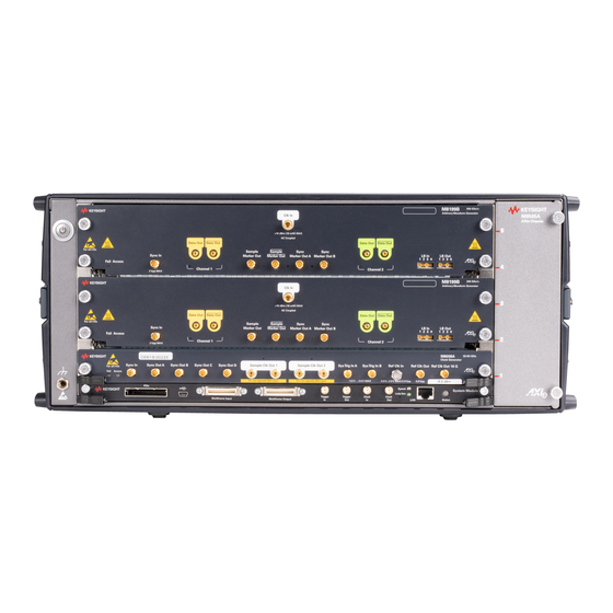
M8008A Clock Generator module. Figure 8 M8199B AWG and M8008A Clock Generator configuration M8199B Module Components Figure 9 on page -26 displays the front panel of the M8199B module: Figure 9 M8199B module front panel M8100A Series Arbitrary Waveform Generators Getting Started Guide... -
Page 27: M8199B Front Panel Connectors
Introduction As displayed in the image above, the M8199B module has the following components. Table 11 Front Panel LEDs Front Panel LED Active when... Color Fail power-up fault condition Access power-up ready state green Table 12 Insertion/Extraction and Retaining Component... - Page 28 16 GHz. Sync Marker Out A/B Marker output to generate subrate clocks for example. Max output bandwidth 2 GHz. The M8199B AWG is controlled by the M8070B software system version 9.5 and above. M8100A Series Arbitrary Waveform Generators Getting Started Guide...
-
Page 29: Basic Setup For M8100A
Step 5 - Connecting the AWG modules / 45 Step 7 - Powering Up (if connecting via PCIe) Step 8 - Verifying Basic Operation of M8199A / M8199B AWG module Step 9 - Installing Keysight IO Libraries Suite (not required for / 47... -
Page 30: Step 1 - Unpacking The Shipment
Guide Series Arbitrary Waveform Generators. Getting Started Guide This document, M8100A Series Arbitrary Waveform Generators Getting Started Guide. (Please check the Keysight website: www.keysight.com/find/M8100A for the latest guide.) Carefully inspect all items in the shipment for any damage. M8100A Series Arbitrary Waveform Generators Getting Started Guide... -
Page 31: Return The Damaged/Defective Item To Keysight For Repair/Replacement
Serial Number field. Contact the nearest Keysight Sales Office. If you need assistance f i n d i n g K e y s i g h t... -
Page 32: Computer Hardware And Software Requirements
1.5 GB or more free hard disc space Software requirements • Windows 10 (64 bit) operating system • Keysight I/O libraries version 17.1 or higher The M8070B software is required to control the M8100A series NOTE instruments. To connect via USB... -
Page 33: Step 4 - Connecting The M9505A Axie Chassis To A Power Supply
Basic Setup for M8100A Review the Keysight recommended list of host computers at http://literature.cdn.keysight.com/litweb/pdf/5990-7632EN.pdf that are compatible with the Keysight M9505A AXIe Chassis. PCIe Port Figure 11 PCIe port on the front panel of the AXIe ESM Step 4 - Connecting the M9505A AXIe Chassis to a Power Supply You can use an external power supply, typically AC power mains. -
Page 34: Step 5 - Connecting The Awg Modules
Basic Setup for M8100A Step 5 - Connecting the AWG modules Performing connections to the M8199A AWG Connecting M8199A-ILV to M8199A Follow the given steps to connect M8199A-ILV assembly to M8199A instrument: Remove M8199A instrument from the AXIe Chassis. Place M8199A instrument and M8199A-ILV on a flat surface (for example on a desk). - Page 35 Basic Setup for M8100A Screw torque will be each screw 1.7 Nm. Place the 8x connectors of the M8199A-ILV on the plugs available on the M8199A front panel. Screw the nut of the connector by hand until you are sure that the nut runs in the thread.
- Page 36 Basic Setup for M8100A Connecting M8008A Clock Generator to M8199A AWG Module The unused output should be disabled on the M8070B software or NOTE terminated with 50 Ohms on the module hardware. Following are the possible ways to connect a M8008A clock source to the M8199A AWG module(s): Case 1 Connecting M8008A clock module to M8199A AWG module...
- Page 37 Case 2 Connecting PSG to an M8199A module Keysight M8257D, Opt. 567, 1EU, UNY (referred to as PSG) is an alternative to the M8008A clock module that can be used as a clock source. In this case, connect the 1.85 mm, 45 cm M8199A-810 replacement channel clock cable (M8199-61624) from the PSG Output to Clk In of M8199A.
- Page 38 Basic Setup for M8100A Case 3 Connecting M8008A clock module to two M8199A AWG modules In this case, a M8008A clock module, two M8199A AWG modules, a M9505A AXIe chassis and the following cables are required: • 3.5 mm, 50 cm M8199A-811 customer orderable sync cable (M8199-61620) •...
- Page 39 Basic Setup for M8100A Case 4 Connecting M8008A clock module to four M8199A AWG modules In this case, a M8008A clock module, four M8199A AWG modules, two M9505A AXIe chassis and the following cables are required: • 3.5 mm, 50 cm M8199A-811 customer orderable sync cable (M8199-61620) •...
- Page 40 Connecting M8008A clock generator to four M8199A AWG modules Enable the Ref Clk Out port in the primary chassis using the web NOTE interface. For details, refer to Keysight M9505A AXIe Chassis Startup Guide. M8100A Series Arbitrary Waveform Generators Getting Started Guide...
-
Page 41: Performing Connections To The M8199B Awg
(M8199-61624) from Sample Clk Out of M8008A to Clk In of M8199B. Connect the 3.5 mm, 50 cm M8199A-811 sync cable (M8199-61620) from Sync Out of M8008A to Sync In of M8199B. Figure 16 on page -41 shows how to connect the M8008A clock generator... - Page 42 Basic Setup for M8100A If you connect more than one M8199B module, you must perform an NOTE additional user calibration using the IQtools user interface to ensure that the skew between modules is stable and corrected. For more information, refer to the IQTools User Guide.
- Page 43 Basic Setup for M8100A Case 3 Connecting M8008A clock module to four M8199B AWG modules In this case, a M8008A clock module, four M8199B AWG modules, two M9505A AXIe chassis and the following cables are required: • 3.5 mm, 50 cm M8199A-811 customer orderable sync cable (M8199-61620) •...
- Page 44 Basic Setup for M8100A Figure 18 Connecting M8008A clock generator to four M8199B AWG modules Enable the Ref Clk Out port in the primary chassis using the web NOTE interface. For details, refer to Keysight M9505A AXIe Chassis Startup Guide.
-
Page 45: Step 7 - Powering Up (If Connecting Via Pcie)
Basic Setup for M8100A Step 7 - Powering Up (if connecting via PCIe) Power up all the connected hardware components in the M9505A AXIe Chassis. Press the ON/Standby button on the front panel of the chassis to power on the chassis. Figure 19 Chassis ON/standby button After powering up the chassis, wait until the Status LED of the ESM is... -
Page 46: Step 8 - Verifying Basic Operation Of M8199A / M8199B Awg Module
Do not use the circuit breaker for routine chassis turn off. The module(s) are turned off automatically with the chassis. Step 8 - Verifying Basic Operation of M8199A / M8199B AWG module After powering ON the connected hardware components, you can verify if you have correctly set up the hardware if: •... -
Page 47: Step 9 - Installing Keysight Io Libraries Suite (Not Required For M8100A-Bu6)
Basic Setup for M8100A Step 9 - Installing Keysight IO Libraries Suite (not required for M8100A-BU6) IO Libraries Suite version 17.1 or later is required. Always use the latest version of the Keysight IO Libraries. Perform this step if you are setting up an M8100A-BU5 system or the... -
Page 48: Step 11 - Starting The M8070B Software
Basic Setup for M8100A on page On the host computer, click on Start > Keysight M8070B > Keysight M8070B. Select the module options from M8070B Startup Options dialog box. For details on the M8070B Startup Options dialog box, refer to M8000 Series User Guide or Online Help. -
Page 49: Step 12 - Installing Module Driver Package In The M8070B Software
M8070B software. The M8199A AWG module requires M8070B software version 7.5 or later installed on your system; whereas the M8199B requires M8070B software version 9.5 or later. Navigate to www.keysight.com/find/M8199A... -
Page 50: Installing Module Licenses (For Upgrades Only)
Basic Setup for M8100A using the Keysight License Manager. It helps you install licenses on your local machine (instrument or computer), or configure your local machine to use licenses from a remote license server. Depending upon the license types, the following version of Keysight License Manager can be used to install the licenses: •... -
Page 51: Step 14 - Starting The Driver Package Interface From M8070B Software
Utilities > Licenses then viewing the license status in the Installed column. Step 14 - Starting the Driver Package Interface from M8070B Software In Windows click on Start > Keysight M8070B > Keysight M8070B. From the M8070B Startup Options dialog box, select a driver package. •... - Page 52 Basic Setup for M8100A Figure 20 M8070B display with M8008A,M8199A selected at Startup Options M8100A Series Arbitrary Waveform Generators Getting Started Guide...
- Page 53 For details on the how to control the driver package using M8070B software interface, refer to M8000 Series User Guide or Online Help. For information on remote programming of the M8199A and M8199B modules using SCPI commands, refer to the M8000 Series Programming Guide.
-
Page 54: Step 15 - Enabling/Disabling The Interleaving Mode In M8199A Modules
Basic Setup for M8100A Step 15 - Enabling/Disabling the Interleaving Mode in M8199A modules There are two different interleaving (ILV) modes: • Non interleaved: This mode is active when no combiner serial no. is registered, and no remote head is connected. •... -
Page 55: Step 16 - Powering Off The Chassis And Modules (If Required)
Step 16 - Powering off the Chassis and Modules (If Required) Power off the chassis and module in the following sequence: Power off the host computer. If you are using the Keysight AXIe Embedded Controller module as the host computer, ensure that you shut down the controller by executing the Windows shutdown process. - Page 57 Keysight M8100A Series Arbitrary Waveform Generators Getting Started Guide Maintenance / 58 Locating Electronic Manuals and Online Help / 58 Routine Care / 59 Updating Software Components / 59 Contacting Keysight Service and Support...
-
Page 58: Maintenance
Various electronic manuals and the M8000 Series Online Help provide information on how to configure and use the supported instrument modules. On installing the M8070B software, you will find documentation by clicking Start > Keysight M8070B > Keysight M8070B Documentation. You can also visit www.keysight.com/find/M8100A to find the latest versions of various manuals and the data sheet for each M8100A module. -
Page 59: Updating Software Components
Guide” (Document Part No. #M8000-91B30). Updating Software Components Updated versions of the M8070B and module specific software components are available on the Keysight website. These software components are available as .EXE files. To download a software upgrade: Go to http://www.keysight.com/find/M8070B. - Page 61 Index Numerics PCIe, power up process, 5-slot AXIe chassis, LAN connection, LEDs Access, 16, 21, Retaining screws, 17, 21, Fail, 16, 21, AXIe chassis, Safety summary, M1800A Series Arbitrary Waveform Generators, Circuit breaker, M9505A, M8070B Software, Combiner S/N, M8070B Software, install, USB connectivity, 12, M8070B Software, starting, M8100A,...
- Page 62 This information is subject to change without notice. © Keysight Technologies 2023 Edition 2.2, March 2023 Printed in Germany www.keysight.com...
Need help?
Do you have a question about the M8199B and is the answer not in the manual?
Questions and answers