Alpha ESS SMILE5 Installation Manual
Hide thumbs
Also See for SMILE5:
- Installation, operation & maintenance manual (113 pages) ,
- User manual (45 pages) ,
- Installation, operation & maintenance manual (33 pages)
Table of Contents
Advertisement
Quick Links
Alpha ESS Co., Ltd.
+86 513 806 068 91
info@alpha-ess.com
www.alpha-ess.com
JiuHua Road 888, Nantong High-Tech Industrial
Development Zone, Nantong City, 226300
Alpha ESS Europe GmbH
+49 610 3459 1601
europe@alpha-ess.de
www.alpha-ess.de
Paul-Ehrlich-Straße 1a, 63225 Langen, Hessen
Alpha ESS Australia Pty. Ltd.
+61 402 500 520 (Sales)
+61 1300 968 933 (Technical Support)
australia@alpha-ess.com
www.alpha-ess.com.au
Suite 1, Level 1, 530 Botany Road, Alexandria,
NSW, 2015
Alpha ESS UK Co., Ltd
uk@alpha-ess.com
Drake House, Long Street, Dursley, gl11 4hh
Alpha ESS Suzhou Co., Ltd.
+86 512 6828 7609
info@alpha-ess.com
www.alpha-ess.com
Building 10-A, Canal Town Industrial Park,
99 Taihu E Rd, Wuzhong District, Suzhou 215000
Alpha ESS Italy S.r.l.
+39 599 239 50
info@alpha-ess.it
www.alpha-ess.it
Via Loda,17-41013 Castelfranco Emilia(MO)
Alpha ESS Korea Co., Ltd
+82 64 721 2004
korea@alpha-ess.com
2F, 19-4, Nohyeong 11-gil, Jeju-si, Jeju-do,
Republic of Korea
INSTALLATION MANUAL
INSTALLATIONMANUAL
ENERGY STORAGE SYSTEM (ESS)
ENERGYSTORAGESYSTEM(ESS)
SMILE5 (DE)
STORION-SMILE-T10(INDOOR)
V04.19052021
Advertisement
Table of Contents

Related Manuals for Alpha ESS SMILE5


Summary of Contents for Alpha ESS SMILE5
- Page 1 V04.19052021 INSTALLATION MANUAL INSTALLATIONMANUAL ENERGY STORAGE SYSTEM (ESS) ENERGYSTORAGESYSTEM(ESS) SMILE5 (DE) STORION-SMILE-T10(INDOOR) Alpha ESS Co., Ltd. Alpha ESS Suzhou Co., Ltd. +86 513 806 068 91 +86 512 6828 7609 info@alpha-ess.com info@alpha-ess.com www.alpha-ess.com www.alpha-ess.com JiuHua Road 888, Nantong High-Tech Industrial...
-
Page 2: Table Of Contents
CONTENTS Copyright Statement This manual is under the copyright of Alpha ESS Co., Ltd. with all rights reserved. Please keep the manual properly and operate in strict accordance with all safety and operating INTRODUCTION instructions in this manual. Please do not operate the system before reading through the manual. -
Page 3: Introduction
4.1 Function Description 1.1 System Introduction 4.2 Introduction 4.2.1 Main AlphaESS SMILE5 (incl. SMILE5-BAT and SMILE-INV) can be applied in DC-coupled 4.2.2 Status systems (mostly new installation), AC-coupled systems (mostly retrofit) and 4.2.3 History Hybrid-coupled systems (mostly retrofit, and PV capacity-increase), as the following 4.2.4 Setting... -
Page 4: Safety Introduction
This sign shows danger of high voltage and electric shock! Normal Loads The SMILE5 must not be touched or put into service until 5 minutes after it has been switched off or disconnected to prevent an electric shock or injury. -
Page 5: General Precautions
Secure the system to prevent tipping with restraining straps in your vehicle. Hazardous materials may be released. Moreover, if heated by close fire, acrid or harmful The transportation of AlphaESS SMILE5 must be made by the manufacturer fume may be emitted. -
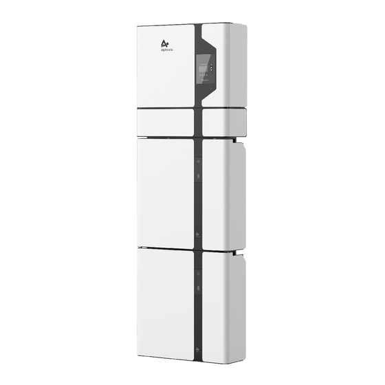
Page 6: Parts List
WiFi Module (1x SM60A or 1x ADL3000 Certficate terminal Manual Card (Optional) or 1x ACR10R) SMILE5-BAT Figure 4 SMILE5 Delivery Scope Object Description 2x Mounting Panel 6x M8*60 6x M5*10 6x M4*10 Hybrid Inverter with Cable Box EMS Display Screen... - Page 7 INTRODUCTION INTRODUCTION Cable Box Part Grid and Backup Terminal Board Figure 7 Cable Box Part without Covers – Front View Item Description Item Description Battery Switch PV Switch Object Description Object Description GRID Grid Switch BACKUP Backup Switch Inverter Debug Net Wire PV1, PV2 PV Connector...
-
Page 8: Liability Limitation
• The maintenance procedures relating to the product have not been followed to an acceptable standard; This SMILE5 energy storage system is an indoor system and can only be installed in • Force majeure (violent or stormy weather, lightning, overvoltage, fire etc.);... -
Page 9: Installation
WiFi Panel and Negative port Installation Diagram Step 2 Connect the power cable at the top, which are included in the parts list of SMILE5-BAT. M5*10 Screws Figure 14 WiFi Module Installation Figure 12 Assemble Battery Mounting Panel Step 5... - Page 10 INSTALLATION INSTALLATION NOTE: Place a cover (paper, foil, etc.) over the battery while drilling into the wall to protect it from INDOOR dust. In addition, at the spot of installation, the slope of the ground on a horizontal plane may not exceed 3°.
-
Page 11: Inverter Installation
COM ports. All of the three cables are regular net cables, type 568B. You can use the communication cable provided in the accessory parts of one SMILE5-BAT as the BMS communication cable. The following figure shows the type 568B line sequence:... - Page 12 INSTALLATION INSTALLATION Step 16 Close the battery front covers and connect the PV-MC4 connectors to the system (connect on both sides). Connect all AC cables to the distribution box, the meter communications cable to the meter COM port, and the ethernet cable to the router. Then close the cable box front cover.
-
Page 13: Single Line Diagram
3-6 by the side of the system. You can connect up to 6 batteries, 2 each mounted on top of each other, to the SMILE5. To do this, carry out the individual installation steps as for the first two batteries, including the DIP setting on the last module. -
Page 14: Power Meter
INSTALLATION INSTALLATION 2.3 Power Meter ADL-3000 single-phase connection (without CT, without meter plug), if applicable: Any product damage or property loss caused by the following conditions AlphaESS does not assume any direct or indirect liability. RJ45 Plug ADL-3000: three-/ single-phase meter (with or without CT) 21 22 SM60A: single-phase meter Backup Box: three-/ single-phase meter (Contain off-grid switching and load... - Page 15 INSTALLATION INSTALLATION 2.3.1.2 Three-phase in house ADL-3000 three-phase connection (with CT, without meter plug), if applicable: ADL-3000 single-phase connection (without CT, without meter plug), if applicable: RJ45 RS485 9 10 1112 L1’ L2’ L3’ N’ ADL-3000 RJ45 LAN1 METER DRMs LAN2 RS485 21 22...
-
Page 16: Meter Sm60A (If Applicable)
INSTALLATION INSTALLATION Option 1: with Meter Plug Option 2: without Meter Plug Note: Cabinet Meter1 Meter2 If the ADL3000 meter with CT is used as a grid meter, the direction of arrow in CT AlphaESS Grid Meter PV Meter should point away from the grid to the energy storage system. RS485 PIN RS485 PORT RS485 PORT... -
Page 17: Backup Box (If Applicable)
Step 3 You will get into the code Step 4 Please set the meter address by Figure 47 Backup Box Connect to SMILE5 (single-phase grid in house) interface. Then click the “Shift” button using the “Value adjusting” button, the Grid to enter the address interface. - Page 18 INSTALLATION INSTALLATION 2.3.5.2 ADL3000 There are 4 buttons on the front of the electricity meter: Prog Prog 000006.45 1. Enter button / Energy button Step 8 Click the “SET” button to Step 9 Click the “SET” button again 2. Down arrow / Power button enter the following interface to enter the save interface 3.
-
Page 19: System Operation
More information can be found in SMILE5-BAT user manual. 3.3 Emergency Procedure When the SMILE5 energy storage system appears to be running abnormally you can turn off the grid connected main switch directly feeding the BESS and turn off all load switches within the BESS, turn off the battery switch at the same time. -
Page 20: Emergency Handling Plan
EMS INTRODUCTION AND SET UP SYSTEM OPERATION 3.3.1 Emergency Handling Plan Effective ways to deal with accidents 1. Disconnect the AC breaker. Battery in dry environment: Place damaged battery into a segregated place and call local fire department or service engineer. 2. - Page 21 EMS INTRODUCTION AND SET UP EMS INTRODUCTION AND SET UP 4.2.1 Main > > > Battery < < < Battery interface displays the real-time Main displays the inverter working status information of battery side: voltage U, > U 48.0V and information, including: current I, power P, residual capacity of Power •...
- Page 22 INV Gen. interface displays today’s or total fault records of this device, including the > Today: electricity quantity generated from name of the fault and time of error. 2018-02-02 16:48 SMILE5-INV. Chg SPI Fault 29.1kWh > > > Bat Gen. < < < > > Information <...
- Page 23 Step 6 Check SOC Calibration Step 5 Click the Battery Function and time. means how much battery energy to function set No. check battery type SMILE5-BAT. reserve for UPS function. > > > > Safety < < < < > > >...
- Page 24 EMS INTRODUCTION AND SET UP EMS INTRODUCTION AND SET UP C. If you use cascading function please set as following steps: Note: It is needed to set the following 3 parameters for manual mode: > > > Function < < < >...
- Page 25 ONLINE MONITORING ONLINE MONITORING CONFIGURATION NETWORK (WIFI OPTIONAL) Please install the WiFi module. Download and install the app by scanning the QR code below, and directly connect to this device by WiFi module. Connect to Router System Connect to Router System the hotspot Configuration...
- Page 26 ONLINE MONITORING ONLINE MONITORING ONLINE MONITORING Installers who haven't registered yet need to click “Register” to visit the registration page. Please refer to “AlphaCloud Online Monitoring Webserver Installers User Manual”, which you can get from AlphaESS sales along with your personal license number. Enter the system S/N, check code, license, installation date, client name, contact number, contact address, and click the save button.
- Page 27 After the equipment are out of operation, Please pay attention to the following notes - Time zone during maintaining process: - Data upload frequency: SMILE5 has second level data, you can choose it as 10s Related safety standards and specifications should be followed in operation and data if you wish.
Need help?
Do you have a question about the SMILE5 and is the answer not in the manual?
Questions and answers