Table of Contents
Advertisement
@AlphaEnergyStorageSystem
@AlphaESS
Alpha ESS Co., Ltd.
+86 513 806 068 91
info@alpha-ess.com
www.alpha-ess.com
JiuHua Road 888, High-Tech Industrial Development
Zone 226300 Nantong City, Jiangsu Province
Alpha ESS Europe GmbH
+
49 610 3459 1601
europe@alpha-ess.de
www.alpha-ess.de
Paul-Ehrlich-Straße 1a 63225 Langen
Alpha ESS Italy S.r.l.
+39 599 239 50
info@alpha-ess.it
www.alpha-ess.it
Via Loda,17-41013 Castelfranco Emilia(MO)
Alpha ESS UK Co., Ltd
uk@alpha-ess.com
Drake House, Long Street, Dursley, gl11 4hh
Alpha ESS USA, Inc.
USA@alpha-ess.com
638 S Ahwanee Ter Sunnyvale, California,
94085 United States of America
@alpha_ess
@AlphaESS
www.alpha-ess.com
Alpha ESS Suzhou Co., Ltd.
+86 512 6828 7609
info@alpha-ess.com
www.alpha-ess.com
Building 10-A, Canal Town Industrial Park,
99 Taihu E Rd, Wuzhong District, Suzhou 215000
Alpha ESS Australia Pty. Ltd.
+61 1300 968 933
australia@alpha-ess.com
www.alpha-ess.com.au
Unit 1, 2 Ralph Street Alexandria NSW 2015
Alpha ESS Korea Co., Ltd
+82 64 721 2004
korea@alpha-ess.com
2F, 19-4, Nohyeong 11-gil, Jeju-si, Jeju-do,
Republic of Korea
Alpha ESS International Pte. Ltd.
Singapore@alpha-ess.com
Blk 55 Ayer Rajah Crescent #01-01, Singapore
139949
INSTALLATION MANUAL
INSTALLATIONMANUAL
ENERGY STORAGE SYSTEM (ESS)
ENERGYSTORAGESYSTEM(ESS)
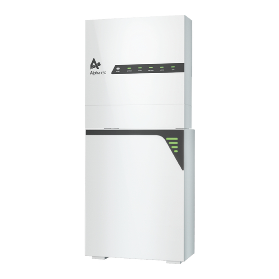
SMILE-T10-HV
STORION-SMILE-T10(INDOOR)
V02
Advertisement
Table of Contents
Troubleshooting

Related Manuals for Alpha ESS SMILE-T10-HV


Summary of Contents for Alpha ESS SMILE-T10-HV
- Page 1 INSTALLATIONMANUAL @AlphaEnergyStorageSystem @AlphaESS @alpha_ess @AlphaESS www.alpha-ess.com ENERGY STORAGE SYSTEM (ESS) ENERGYSTORAGESYSTEM(ESS) Alpha ESS Co., Ltd. Alpha ESS Suzhou Co., Ltd. +86 513 806 068 91 +86 512 6828 7609 SMILE-T10-HV STORION-SMILE-T10(INDOOR) info@alpha-ess.com info@alpha-ess.com www.alpha-ess.com www.alpha-ess.com Building 10-A, Canal Town Industrial Park,...
-
Page 2: Table Of Contents
CONTENT Copyright Statement This manual is under the copyright of Alpha ESS Co., Ltd. with all rights reserved. Please INFORMATION ON THIS DOCUMENT keep the manual properly and operate in strict accordance with all safety and operating 1.1 Content and Structure of this Document instructions in this manual. -
Page 3: Information On This Document
1.1 Content and Structure of this Document 7.6 PV Connection 7.7 Battery Power Connection This document is valid for product of SMILE-T10-HV system which include inverter SMILE-T10-HV-INV, battery pack SMILE-BAT-8.2PH. 7.8 Mounting the Cable Cover This document describes the mounting, installation, commissioning, configuration, 7.9 Battery Pack Expansion Connection... -
Page 4: Nomenclature
Inverter (INDOOR) Use this product only in accordance with the information provided in the enclosed Inverter (OUTDOOR) SMILE-T10-HV-INV (OUTDOOR ) documentation and with the locally applicable standards and directives. Any other application may cause personal injury or property damage. Product SMILE-T10-HV-INV with SMILE-BAT-8.2PH... -
Page 5: Important Safety Instructions
SAFETY SAFETY 2.2.2 Response to Emergency Situations 2.3 Important Safety Instructions This section contains safety precautions that must be observed at all times when working The Battery pack comprises multiple batteries that are designed to prevent hazards on or with the product. resulting from failures. - Page 6 SAFETY SAFETY DANGER CAUTION Danger to life due to electric shock when touching live system components in case of a Risk of burns due to hot heatsink and housing ground fault The heatsink and housing can get hot during operation. During operation, do not touch any parts other than the cover of the inverter.
-
Page 7: Symbols On The Label
SAFETY SAFETY 2.4 Symbols on the label Symbols on the type label and warning label of the battery pack: Symbols on the Type Label of the Inverter Symbol Explanation Symbol Explanation Beware of a danger zone This symbol indicates that the product must be additionally grounded if additional Beware of a danger zone This symbol indicates that the product must be additionally grounded if grounding or equipotential bonding is required at the installation site. -
Page 8: Product Introduction And Application Scenarios
PRODUCT INTRODUCTION AND APPLICATION SCENARIOS PRODUCT INTRODUCTION AND APPLICATION SCENARIOS Product Introduction and Application Scenarios LED Indictor Status Explanation 3.1 Inverter Description The battery pack works normally. BATTERY Battery communication exists but is not working Inverter appearance and dimensions normally 230mm 580mm Battery communication lost... -
Page 9: Battery Pack Description
When the battery is being charged, the fourth line of the LED indicator will flash every 3s. 3.3 Application Scenarios AlphaESS SMILE-T10-HV system (include SMILE-T10-HV-INV and SMILE-BAT-8.2PH) can be applied in DC-coupled systems (mostly new installation), AC-coupled systems (mostly retrofit) and Hybrid-coupled systems (mostly retrofit, and PV capacity -increase),... -
Page 10: Storage
PRODUCT INTRODUCTION AND APPLICATION SCENARIOS STORAGE Storage Indicates a power cable Indicates a signal cable 4.1 Inverter Storage Critical Loads Normal Loads The following requirements should be met if the inverter is not put into use directly: Do not unpack the inverter. Breaker Backup Keep the storage temperature at -40~70°C and the humidity at 5%~95% RH. -
Page 11: Unpacking
Check the scope of delivery for completeness and any externally visible damage. (X1) (X6) Paper Plate (X1) Bracket (X1) Contact your distributor if the scope of delivery is incomplete or damaged. SMILE-T10-HV-INV (INDOOR/OUTDOOR) Hybrid Inverter Wall Anchor Cardboard limit board Battery COM Cable Power Cable + (X 1) Inverter... -
Page 12: Mounting
SMILE-T10-HV-INV (OUTDOOR) and SMILE-BAT-8.2PH (OUTDOOR) are suitable for indoor and outdoor use. SMILE-T10-HV-INV (INDOOR) and SMILE-BAT-8.2PH (INDOOR) are suitable for only indoor use. Do not install the inverter in a place where a person can easily touch it because its housing and heat sinks are extremely hot during operation. -
Page 13: Preparing Tools And Instruments
MOUNTING MOUNTING 6.3 Mounting the Battery Pack and Inverter 6.2 Preparing Tools and Instruments 6.3.1 Mounting the battery pack Category Tools and Instruments Lift the battery pack by using the handles at the two sides, take it out from the package carton. Do not put the battery pack upside down on the ground. Multimeter (DC voltage Hammer drill (with a Torque socket... - Page 14 MOUNTING MOUNTING Place the battery against the wall, align the holes at the battery side to the screw holes After cleaning the dust and other objects from the two holes, place 2 wall anchors into of the wall bracket. the holes, then attach the battery wall bracket to the wall by using the SW10 hexagon Tighten the wall bracket and the battery pack with screw M5*12 (X 2) (tool: T20 sleeve.
- Page 15 MOUNTING MOUNTING 6.3.2 Mounting the inverter 2) For battery stack, lock the screw M6*6 on top of the first battery pack. Place the battery positioning paper plate against the wall and the bottom with notch against the first battery pack. Repeat steps 1-7. Dimensions in mm The steps to mount the inverter are listed below: Fit the bottom of the inverter's positioning paper plate into the top of the battery...
- Page 16 MOUNTING MOUNTING 6.3.3 Mounting the WiFi module Attach the wall bracket to the wall using the screws with the tool of SW10 hexagon sleeve. Remove the WiFi cover from the top of the inverter with Torx 20 screwdriver. Hold the inverter by using the handles at two sides, attach the inverter onto the wall bracket tilted slightly downwards.
-
Page 17: Electrical Connection
ELECTRICAL CONNECTION ELECTRICAL CONNECTION Electrical Connection Position Designation PV switch Precautions 2 positive and 2 negative PV connectors, PV input A DANGER 2 positive and 2 negative PV connectors, PV input B 1 positive and 1 negative BAT power connectors Before connecting cables, ensure that all switch and breaker of the inverter and the battery pack and all the switches connected to inverter and the battery pack are set to OFF. -
Page 18: Preparing Cables
ELECTRICAL CONNECTION ELECTRICAL CONNECTION 7.1.2 Overview of the Battery Pack Connection Area 7.3 Connecting Additional Grounding An external grounding connection is provided at the bottom sides of the inverter. Battery Breaker Prepare M5 OT terminals, strip the grounding cable insulation, insert the stripped part of the grounding cable into the ring terminal lug and crimp using a crimping tool. - Page 19 ELECTRICAL CONNECTION ELECTRICAL CONNECTION Do not connect loads between the inverter and the grid breaker. 3.Dismantle the AC cable by 80 mm, and strip the insulation of L1, L2, L3, N and the grounding conductor by 10mm. No consumer load should be applied between the AC circuit breaker and the inverter. Use dedicated circuit breakers with load switch functionality for load switching.
- Page 20 The inverter is equipped with an all-pole sensitive residual current monitoring unit RJ45 (RCMU) with an integrated differential current sensor which fulfills the requirement of DIN VDE0100-712(IEC60364-7-712:2002). SMILE-T10-HV-INV Therefore, an external residual current device (RCD) is not required. If an external RCD L1 L2 L3 L1 L2 L3 needs to be installed because of local regulations, a RCD type A or type B can be installed as an additional safety measure.
- Page 21 ELECTRICAL CONNECTION ELECTRICAL CONNECTION Meter Address Setting Step 2: Click "Save" and wait a few minutes to refresh the page. Model Grid Meter Address PV Meter Address When the “Meter Model” displays DTSU666 model, the setting is successful. DTSU666-3*230 V 5 A NOTE: ( without CT ) It is forbidden to tick CT to modify the CT ratio.
-
Page 22: Communication Connection
ELECTRICAL CONNECTION ELECTRICAL CONNECTION 1) Connect the BMS port on the inverter and COM port on the battery with 7.4.5 Backup Box PLUS Connection communication cable. 2) For meter wiring, please read electricity meter wiring instructions of the meter. NOTICE 3) If DRM support is specified, the system may only be used in conjunction with a The residual current device (RCD) should be connected to the load side. -
Page 23: Battery Power Connection
ELECTRICAL CONNECTION ELECTRICAL CONNECTION 7.7 Battery Power Connection Insert the cable cover against the bottom edge of the inverter. Please follow the below steps for battery power connection. Disconnect the battery circuit breaker and secure it against reconnection. Take out the battery power cables which are provided by the battery pack. Ensure the correct polarity of power cable of the batteries before connecting to the inverter. - Page 24 ELECTRICAL CONNECTION WIFI SETTING WiFi Setting 8.1 Download and Install the Application Android device users can download the app through major Android application markets such as Google Play. IOS device users can search for “AlphaESS” in App Store and download the app.
-
Page 25: Wifi Setting
WIFI SETTING WIFI SETTING 8.2 Overview of Functions for Installer Account 8.3 WiFi Module Setting This section is for users who have a system with a WiFi module. AlphaESS App supports network configuration, setting of the system basic parameter, and the viewing of system operation and configuration information. - Page 26 WIFI SETTING WIFI SETTING AL40010109000000 Step 4: Select the WiFi of your home you are using, enter the password, complete the WiFi configuration and submit. If there is no network currently, you can Password click Jump over to skip the WiFi configuration step and directly set the 12345678 system parameters.
-
Page 27: Commissioning
COMMISSIONING COMMISSIONING the indicators states on the display panel of the inverter. At this time, the following 4 LEDs Commissioning ("SYSTEM", "BATTERY", "METER", "COM") on the display panel is always on. 9.1 Checking Before Power-On Table 9-1 Installation checklist Check Item Acceptance Criteria The battery pack and inverter are mounted correctly, Battery pack and... -
Page 28: Maintenance And Troubleshooting
MAINTENANCE AND TROUBLESHOOTING MAINTENANCE AND TROUBLESHOOTING 10.2 Troubleshooting Maintenance and Troubleshooting 10.2.1 Inverter Error Troubleshooting 10.1 Routine Maintenance Error No. Error description Solution Normally, the inverter and battery pack need no maintenance or calibration. Grid_OVP 100000 However, in order to maintain the accuracy of the SOC, it is recommended to perform a 1. -
Page 29: Troubleshooting
MAINTENANCE AND TROUBLESHOOTING MAINTENANCE AND TROUBLESHOOTING 10.2.2 Battery Protection Description Error No. Error description Solution Restart inverter and ensure whether Protection LED Indictor Description Troubleshooting Grid_current_track_fault 100051 Display the fault is existing. Code 1. Check whether Backup port cable Wait for automatical recovery. If Temperature is normal. - Page 30 MAINTENANCE AND TROUBLESHOOTING MAINTENANCE AND TROUBLESHOOTING 10.2.3 Battery Error Description NOTE: Error Code LED Indictor Description Troubleshooting In the case of work mode, when the protection code NO. 9 appears, please quickly push the Power Display button 5 times in 10 seconds to force the BMS start up the MOSFET of discharging. Thus the open-circuit voltage of the battery will be detected by the inverter and get charged.
-
Page 31: Uninstallation & Return
UNINSTALLATION & RETURN SPECIFICATION Uninstallation & Return Specification 11.1 Removing the Product 12.1 Datasheet of Hybrid Inverter SMILE-T10-HV-INV Procedure Item SMILE-T10-HV-INV (OUTDOOR) SMILE-T10-HV-INV (INDOOR) Step 1 Power off the product by following the instructions in section 9.3 Powering Input DC (PV side) Off... -
Page 32: Datasheet Of Battery Pack Smile-Bat-8.2Ph
SPECIFICATION SPECIFICATION Max. input current PV switch 22 A Integrated Output AC(Grid side) Battery breaker Integrated General data Rated output power 10 kW Max. apparent output 580*606*230 mm Dimensions(W*H*D) 10 kVA power Weight 30 kg Operation phase Three phase Topology Transformerless Rated grid voltage L1/ L2/ L3/N/PE, 220/380 V, 230/400 V... - Page 33 Australia B Appendix 1: Communication Connection Figure Australia C Indicates a signal cable Ausnet Services WiFi/4G Optional Jemena Victoria Citipower Powercor SMILE-T10-HV-INV United Energy Energex Home Appliances Queensland Ergon Energy BMS CAN/RS485 METER LAN SA Power Router South Australia Networks...
Need help?
Do you have a question about the SMILE-T10-HV and is the answer not in the manual?
Questions and answers