Table of Contents
Advertisement
@AlphaEnergyStorageSystem
@AlphaESS
Alpha ESS Co., Ltd.
+86 513 8060 6891
info@alpha-ess.com
www.alpha-ess.com
JiuHua Road 888, High-Tech Industrial Development
Zone 226300 Nantong City, Jiangsu Province
Alpha ESS Europe GmbH
+ 49 610 3459 1601
europe@alpha-ess.de
www.alpha-ess.de
Paul-Ehrlich-Straße 1a 63225 Langen
Alpha ESS Italy S.r.l.
+39 599 239 50
info@alpha-ess.it
www.alpha-ess.it
Via Loda,17-41013 Castelfranco Emilia(MO)
Alpha ESS UK Co., Ltd
uk@alpha-ess.com
Drake House, Long Street, Dursley, gl11 4hh
Alpha ESS USA, Inc.
USA@alpha-ess.com
638 S Ahwanee Ter Sunnyvale, California,
94085 United States of America
@alpha_ess
@AlphaESS
www.alpha-ess.com
Alpha ESS Suzhou Co., Ltd.
+86 512 6828 7609
info@alpha-ess.com
www.alpha-ess.com
Building 10-A, Canal Town Industrial Park,
99 Taihu E Rd, Wuzhong District, Suzhou 215000
Alpha ESS Australia Pty. Ltd.
+61 1300 968 933
australia@alpha-ess.com
www.alpha-ess.com.au
Unit 1, 2 Ralph Street Alexandria NSW 2015
Alpha ESS Korea Co., Ltd
+82 64 721 2004
korea@alpha-ess.com
2F, 19-4, Nohyeong 11-gil, Jeju-si, Jeju-do,
Republic of Korea
Alpha ESS International Pte. Ltd.
Singapore@alpha-ess.com
Blk 55 Ayer Rajah Crescent #01-01, Singapore
139949
INSTALLATION MANUAL OF
INSTALLATIONMANUAL
ENERGY STORAGE SYSTEM (ESS)
ENERGYSTORAGESYSTEM(ESS)
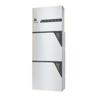
STORION-SMILE-T10(INDOOR)
SMILE-S6-HV
V03
Advertisement
Table of Contents

Related Manuals for Alpha ESS SMILE-S6-HV


Summary of Contents for Alpha ESS SMILE-S6-HV
- Page 1 @AlphaEnergyStorageSystem @AlphaESS @alpha_ess @AlphaESS www.alpha-ess.com STORION-SMILE-T10(INDOOR) SMILE-S6-HV Alpha ESS Co., Ltd. Alpha ESS Suzhou Co., Ltd. +86 513 8060 6891 +86 512 6828 7609 info@alpha-ess.com info@alpha-ess.com www.alpha-ess.com www.alpha-ess.com Building 10-A, Canal Town Industrial Park, JiuHua Road 888, High-Tech Industrial Development...
-
Page 2: Table Of Contents
CONTENT Copyright Statement This manual is under the copyright of Alpha ESS Co., Ltd. with all rights reserved. Please INFORMATION ON THIS DOCUMENT keep the manual properly and operate in strict accordance with all safety and operating 1.1 Information on this Document instructions in this manual. -
Page 3: Information On This Document
INFORMATION ON THIS DOCUMENT Information on this Document 1.1 Content and Structure of this Document 7.2 Preparing Cables This document is valid for product of SMILE-S6-HV which include inverter 7.3 Connecting Additional Grounding SMILE-S6-HV-INV, battery pack SMILE-BAT-8.2PH or SMILE-BAT-5PH. 7.4 AC Connection This document describes the mounting, installation, commissioning, configuration,... -
Page 4: Nomenclature
SMILE-S6-HV-INV (OUTDOOR) Inverter (OUTDOOR) application may cause personal injury or property damage. Alterations to the product, e.g. changes or modifications, are only permitted with the SMILE-S6-HV-INV with SMILE-BAT-8.2PH Product express written permission of AlphaESS. Unauthorized alterations will void or SMILE-BAT-5PH guarantee and warranty claims. -
Page 5: Response To Emergency Situations
SAFETY SAFETY 2.2.2 Response to emergency situations 2.3 Important Safety Instructions This section contains safety precautions that must be observed at all times when working The battery pack comprises multiple batteries that are designed to prevent hazards on or with the product. resulting from failures. - Page 6 SAFETY SAFETY DANGER CAUTION Danger to life due to electric shock when touching live system components Risk of burns due to hot heatsink and housing in case of a ground fault. The heatsink and housing can get hot during operation. If a ground fault occurs, parts of the system may still be live.
-
Page 7: Symbols On The Label
SAFETY SAFETY 2.4 Symbols on the label Symbols on the type label and warning label of the battery pack Symbols on the type label of the inverter Symbol Explanation Symbol Explanation Beware of a danger zone This symbol indicates that the product must be additionally grounded if additional Beware of a danger zone grounding or equipotential bonding is required at the installation site. -
Page 8: Product Introduction And Application Scenarios
PRODUCT INTRODUCTION AND APPLICATION SCENARIOS PRODUCT INTRODUCTION AND APPLICATION SCENARIOS LED Indictor Status Explanation Product Introduction and Application Scenarios The battery pack works normally 3.1 Inverter Description BATTERY Inverter appearance and dimensions Battery communication exists but is not working normally Battery communication is lost Meter communication works normally Meter communication is lost... -
Page 9: Battery Pack Description
Different colors represent different states: green for SOC , yellow for Protection , red for Error. 3.3 Application Scenarios AlphaESS SMILE-S6-HV system (includes SMILE-S6-HV-INV and SMILE-BAT-8.2PH or SMILE-BAT-5PH) can be applied in DC-coupled systems (mostly new installation), AC-coupled systems (mostly retrofit) , Hybrid-coupled systems (mostly retrofit, and increase the PV capacity), and Off-grid (with Generator) systems as the following... - Page 10 PRODUCT INTRODUCTION AND APPLICATION SCENARIOS PRODUCT INTRODUCTION AND APPLICATION SCENARIOS Indicates a power cable Indicates a signal cable Indicates a power cable Crtical Loads Indicates a signal cable Normal Loads Breaker Backup Critical Load Breaker SMILE Grid Inverter Grid Breaker Backup Grid Meter Breaker...
-
Page 11: Storage
Replace the packing materials that are damaged by insects or rodents in a timely manner. 6. If the inverters have been stored for more than two years, it must be checked and SMILE-S6-HV-INV Hybrid Inverter tested by professionals before being put into use. 4.2 Battery Storage The following requirements should be met if the battery pack is not put into use directly: 1. - Page 12 UNPACKING UNPACKING SMILE-BAT-8.2PH SMILE-BAT-5PH Battery Pack Floor Gasket Battery Positioning Battery Wall Battery Positioning Ring Terminal Lug Upper Cover Plate Screw M5*10 (X2) (X1) (X1) (X3) Paper Plate (X1) Bracket (X1) Paper Plate (X1) (X2) Wall Anchor Cardboard limit board Battery COM Cable Power Cable + (X 1) Screw M5*12...
-
Page 13: Mounting
Do not mount the product in areas containing highly flammable materials or gases. Do not mount the product in potentially explosive atmospheres. Basic Requirements SMILE-S6-HV-INV (OUTDOOR) and SMILE-BAT-8.2PH (OUTDOOR) are suitable for indoor and outdoor use. SMILE-S6-HV-INV (INDOOR) and SMILE-BAT-8.2PH (INDOOR) and SMILE-BAT-5PH (INDOOR) are suitable for only indoor use. -
Page 14: Preparing Tools And Instruments
MOUNTING MOUNTING 6.3 Mounting the SMILE-BAT-8.2PH and Inverter 6.2 Preparing Tools and Instruments 6.3.1 Mounting the battery pack Category Tools and Instruments 1. Lift the battery pack by using the handles at the two sides, take it out from the package carton. - Page 15 MOUNTING MOUNTING 4. After cleaning the dust and other objects from the two holes, place 2 wall anchors into 7. Tighten the wall bracket and the battery pack with screw M5*12 (X 2) (tool: T20 the holes, then attach the battery wall bracket to the wall by using the SW10 hexagon screwdriver, torque: 2.5Nm).
- Page 16 MOUNTING MOUNTING 2) For battery stack, lock the screw M6*6 on top of the first battery pack. 6.3.2 Mounting the inverter Dimensions in mm 3) Place the battery positioning paper plate against the wall and the bottom with notch against the first battery pack. Repeat steps 1-7. The steps to mount the inverter are listed below: 1.
-
Page 17: Mounting The Smile-Bat-5Ph And Inverter
MOUNTING MOUNTING 3. Attach the wall bracket to the wall by using the screws with the tool of SW10 6. Remove the small support parts of the inverter cover and the two screws will be used hexagon sleeve. Please use a level to ensure that the wall bracket is horizontal. to connect to grounding point. - Page 18 MOUNTING MOUNTING 7. Tighten the wall bracket and the inverter with screw M6*16 (X 3) (tool: T20 3. Place the battery's positioning paper plate against the wall, fit holes of the paper plate screwdriver, torque: 3.0Nm). named B1 with the bottom two holes, mark the positions of the drill holes named A1 and A2 on the paper plate.
-
Page 19: Mounting The Wifi Module
MOUNTING MOUNTING 10. Tighten the battery wall bracket and the battery with screw M6*16 (X 4) (tool: T20 screwdriver, torque: 3.0Nm). ≥ ≥370 11. Mounting more batteries You can install extra batteries up to 6 batteries in a system. 4) If the expansion batteries are installed by side: 1) If the expansion batteries are installed downwards: Position the positioning paper plate according to the installed batteries, and then repeat Attach the positioning paper plate to the first wall bracket, and mark the wall through... -
Page 20: Electrical Connection
ELECTRICAL CONNECTION ELECTRICAL CONNECTION Electrical Connection Position Designation PV switch Precautions 1 positive and 1 negative PV connectors, PV input A DANGER Before connecting cables, ensure that all switches and breakers of the inverter 1 positive and 1 negative PV connectors, PV input B and the battery pack and all the switches connected to inverter and the battery Communication port(BMS, CAN/RS485, Meter/Grid-CT, pack are set to OFF. -
Page 21: Preparing Cables
ELECTRICAL CONNECTION ELECTRICAL CONNECTION 7.2 Preparing Cables 7.1.2 Overview of the Battery Pack Connection Area The battery breaker is switched off before delivery Outer Conductor Cross Cable Type Source Diameter Section Area Range a) SMILE-BAT-8.2PH (INDOOR) Standard PV cable in the Delivered Battery industry (recommended... -
Page 22: Connecting Additional Grounding
ELECTRICAL CONNECTION ELECTRICAL CONNECTION 7.3 Connecting Additional Grounding c) SMILE-BAT-5PH (INDOOR) An external grounding connection is provided at the left side of the inverter. Prepare M5 OT terminals, strip the grounding cable insulation, insert the stripped part of the grounding cable into the ring terminal lug and crimp using a crimping tool. Connect the OT terminal with ground point using the torque is 2.5 Nm with T20 screwdriver. - Page 23 ELECTRICAL CONNECTION ELECTRICAL CONNECTION 7.4.2 Grid and Backup Connection 4. Insert the stripped part of the conductors into the cord end terminals and crimp them using a crimping tool. There are two AC terminal blocks for grid and backup connection which have the same installation steps.
- Page 24 For AC-coupled systems and Hybrid-coupled systems, another PV-CT is required . Buckle the PV-CT on the live wire of the PV inverter connecting point and insert the registered LOAD jack of the PV-CT cable into the PV-CT port on the SMILE-S6-HV-INV. GRID PV Inverter...
- Page 25 ELECTRICAL CONNECTION ELECTRICAL CONNECTION RJ45 Grid CT PV CT 1--------IC (White) 31--------IC (White) L1 L2 L3 SMILE-S6-HV-INV 3--------IC (Blue) 33--------IC (Blue) 4--------IB (White) 34--------IB (White) 6--------IB (Blue) 36--------IB (Blue) 7--------IA (White) 37--------IA (White) LOAD 9--------IA (Blue) 39--------IA (Blue) L1 L2 L3 N...
- Page 26 ELECTRICAL CONNECTION ELECTRICAL CONNECTION Meter Setting on AlphaAPP *2 ( Step1) Value → → Code *1 ( Step2) Display Step 1 When the system work mode is selected as DC, only tick the “Meter” on the right of the *1 ( Step1) Value →...
- Page 27 ELECTRICAL CONNECTION ELECTRICAL CONNECTION 2) Backup Box-PLUS Connection Three/single-phase meter (Contain off-grid switching) Description Maximum current per phase Backup Box Backup Box-PLUS 1) Backup Box Connection Backup Box-PLUS connection at single-phase home Backup Box connection at single-phase home Bypass GRID_L1 LOAD_L1 LOAD1 LOAD2 LOAD3 PV-INV_L1...
-
Page 28: Communication Connection
Demand Response Enabling Device (DRED) must be connected in the same network. power factor and frequency of the generator unit. If this solution is not followed, the gener- Only DRM0 is available for SMILE-S6-HV. ator could shut down when the load is suddenly increased due to the high battery charge-... -
Page 29: Pv Connection
ELECTRICAL CONNECTION ELECTRICAL CONNECTION The inverter uses the H4 PV connectors. Please follow the picture below to assemble the 2. Place the COM connection cover against the inverter and tighten them. H4 connectors. PV cable cross section requirements: 4 mm positive terminal negative terminal Inverterter terminal... -
Page 30: Battery Pack Expansion Connection
ELECTRICAL CONNECTION ELECTRICAL CONNECTION 7.8 Battery Pack Expansion Connection You can install extra batteries up to 6 batteries in a system. Please install extra SMILE-BAT-8.2PH batteries by side, also batteries can be stacked up to two batteries per column. Connect the power cables from battery 2 to battery 1. Connect the BMS communication cables from battery 2 to battery 1. -
Page 31: Wifi Setting
WIFI SETTING WIFI SETTING 8.2 Overview of Functions for Installer Account WiFi Setting 8.1 Download and Install APP 1.Android device users can download the APP through major Android application markets such as Google Play. 2.IOS device users can search for “AlphaESS” in App Store and download the APP. AlphaESS-APP... -
Page 32: Wifi Module Setting
WIFI SETTING WIFI SETTING 8.3 WiFi Module Setting This section is for users who have a system with a WiFi module. AlphaESS App supports network configuration, setting of the system basic parameter, and Connect to Router System the viewing of system operation and configuration information. the hotspot Configuration Configuration... -
Page 33: Commissioning
WIFI SETTING COMMISSIONING Please set the safety standard appropriate for your country or purpose via APP or Web during pilot Commissioning run. 9.1 Checking Before Power-On The safety standard must be set correctly Check Item Acceptance Criteria The mounting space is proper, and the mounting If you select a safety standard which is not valid for your country and purpose, it can Mounting environment environment is clean and tidy, without foreign object. -
Page 34: Powering Off The Product
COMMISSIONING MAINTENANCE AND TROUBLESHOOTING Maintenance and Troubleshooting 10.1 Routine Maintenance Normally, the inverter and battery pack need no maintenance or calibration. 3. Check the UPS state of the product However, in order to maintain the accuracy of the SOC, it is recommended to perform a Switch off... -
Page 35: Maintenance And Troubleshooting
MAINTENANCE AND TROUBLESHOOTING MAINTENANCE AND TROUBLESHOOTING 10.2 Troubleshooting Error No. Error description Solution 10.2.1 Inverter Error Troubleshooting Check the PV1 voltage. If it exceeds 585VDC, MPPT1_OVP 100017 reduce the number of PV modules. Error No. Error description Solution 1. Try to reduce the PV power. MPPT1_SW_OCP 100018 Grid_OVP... - Page 36 MAINTENANCE AND TROUBLESHOOTING MAINTENANCE AND TROUBLESHOOTING Error No. Error description Solution Error No. Error description Solution 1. If the battery is not connected, use a multimeter 1. Try to lower the ambient temperature. to measure whether there is voltage at the battery 2.
-
Page 37: Uninstallation & Return
MAINTENANCE AND TROUBLESHOOTING UNINSTALLATION & RETURN 10.2.3 Battery Error Description Uninstallation & Return LED Indictor Description Troubleshooting Error Code Display 11.1 Removing the Product Procedure Hardware error Error 01 Step 1 Power off the product by following instructions in chapter 9.3 Powering Off the Product. -
Page 38: Specification
SPECIFICATION SPECIFICATION Specification Rated Input Power 12 kW 9.2 kW Max. input current 52.2 A 40 A 12.1 Datasheet of Hybrid Inverter SMILE-S6-HV-INV Output AC(Grid side) SMILE-S6-HV-INV SMILE-S6-HV-INV Rated output power 6 kW 4.6 kW Item (OUTDOOR) (INDOOR)* Max. Apparent Output 6 kVA 4.6 kVA... -
Page 39: Datasheet Of Battery Pack Smile-Bat-8.2Ph
SPECIFICATION SPECIFICATION General data Internal Resistance ≤90 mΩ Max. Charging/ 580*440*230 mm Dimensions(W*H*D) 1.2C (38.4 A) 1C (32 A) Discharging Current** Weight 25 kg Operating Temperature Charge:0<T<50°C / Discharge:-10<T<50°C Topology Transformerless Range Operation Temperature Relative Humidity 0% ~ 95% 15% ~ 85% -25 ~ +60 °C Range System voltage, current, cell voltage,... -
Page 40: Appendix 1:Communication Connection Figure
COMMUNICATION CONNECTION FIGURE REGIONAL APPLICATION STANDARD Appendix 1:Communication Connection Figure Appendix 2: Regional application Standard WiFi/4G Regional application Standard Electric Company SMILE-S6-HV-INV Australia A Home Appliances CAN/ METER/ RS485 PV - CT Australia B GRID - CT Router Australia C...
Need help?
Do you have a question about the SMILE-S6-HV and is the answer not in the manual?
Questions and answers