
Related Manuals for Alpha ESS SMILE-S6 Series


Summary of Contents for Alpha ESS SMILE-S6 Series
- Page 1 Installation Manual Energy Storage System (ESS) SMILE-S6 SMILE-S5 SMILE-S3.6 SMILE-B5 series...
-
Page 2: Imprint
E-mail: info@alpha-ess.com Web: www.alpha-ess.com Add: JiuHua Road 888, High-Tech Industrial Development Zone 226300 Nantong City, Jiangsu Province Australia Alpha ESS Australia Pty. Ltd. Tel.: +61 1300 968 933 E-mail: australia@alpha-ess.com Web: www.alpha-ess.com.au Add: Unit 1, 2 Ralph Street Alexandria NSW 2015 Italy Alpha ESS Italy S.r.l. -
Page 3: Copyright Statement
Please keep the manual properly and operate in strict accordance with all safety and operating instructions in this manual. Please do not operate the product before reading through the manual. Version Information Version Date Content 25.12.2021 ___________________________________________________________________ Alpha ESS Co., Ltd. Page 3 of 74... -
Page 4: Table Of Contents
6.3 Mounting Inverter and Expansion Battery Pack ..........24 7. Electrical Connection ..................33 7.1 Overview of the Connection Area ..............34 7.2 Preparing Cables ....................35 7.3 Connecting Additional Grounding ..............36 7.4 AC Connection ....................38 ___________________________________________________________________ Alpha ESS Co., Ltd. Page 4 of 74... - Page 5 11.3 Disposing of the Product ................... 68 Appendix 1: Communication Connection Figure ............. 69 Appendix 2: Regional Application Standard ............70 Appendix 3: System Connection Diagrams ............. 71 Appendix 4: Technical Data of SMILE-S6/S5/S3.6/B5 series ........72 ___________________________________________________________________ Alpha ESS Co., Ltd. Page 5 of 74...
-
Page 6: Information On This Document
DANGER indicates a hazardous situation which, if not avoided, will result in death or serious injury. WARNING WARNING indicates a hazardous situation which, if not avoided, could result in death or serious injury. ___________________________________________________________________ Alpha ESS Co., Ltd. Page 6 of 74... - Page 7 NOTICE NOTICE indicates a situation which, if not avoided, can result in property dam- age. INFORMATION provides tips which are valuable for the optimal installation and operation of the product. ___________________________________________________________________ Alpha ESS Co., Ltd. Page 7 of 74...
-
Page 8: Nomenclature
5kW AC coupled system with 25.20kWh battery SMILE-B5 VI 6kW Hybrid system with 30.24kWh battery In this manual, the SMILE-S5 will represent all the model number of the energy storage system becasue they share the same topologic. ___________________________________________________________________ Alpha ESS Co., Ltd. Page 8 of 74... -
Page 9: Safety
Do not connect any AC conductors or PV conductors directly to the Battery Pack which should be only connected to the Inverter. Do not charge or discharge damaged battery. ___________________________________________________________________ Alpha ESS Co., Ltd. Page 9 of 74... - Page 10 In water: Stay out of the water and don't touch anything if any part of the battery, inverter, or wiring is submerged. Do not use submerged battery again and contact the service engineer. ___________________________________________________________________ Alpha ESS Co., Ltd. Page 10 of 74...
-
Page 11: Important Safety Instructions
Disconnect the product from voltage sources and make sure it cannot be reconnected before working on the inverter or the battery pack. ___________________________________________________________________ Alpha ESS Co., Ltd. Page 11 of 74... - Page 12 Damage due to cleaning agents The use of cleaning agents may cause damage to the product and its components. Clean the product and all its components only with a cloth moistened with clear water. ___________________________________________________________________ Alpha ESS Co., Ltd. Page 12 of 74...
-
Page 13: Symbols On The Label
EU Equipment and Product Safety Act. CE marking The product complies with the requirements of the applicable EU directives. RCM (Regulatory Compliance Mark) The product complies with the requirements of the applicable Australian standards. ___________________________________________________________________ Alpha ESS Co., Ltd. Page 13 of 74... - Page 14 Do not dispose of the battery pack together with the house- hold waste but in accordance with the locally applicable dis- posal regulations for batteries Recycling code Marking for transport of dangerous goods The product passes the certifications of the UN38.3 ___________________________________________________________________ Alpha ESS Co., Ltd. Page 14 of 74...
-
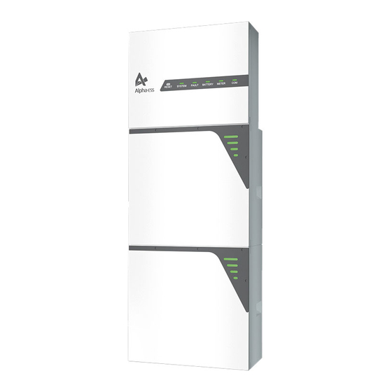
Page 15: Product Introduction And Application Scenarios
Your Smart Energy 3. Product Introduction and Application Scenarios Product Description Appearance and Dimensions (mm) ___________________________________________________________________ Alpha ESS Co., Ltd. Page 15 of 74... - Page 16 The LED indicators provide information about the SOC operational status of the battery pack. SOC Status Description SOC<5% 5%=<SOC<25% 25%=<SOC<50% SOC Instruction 50%=<SOC<75% 75%=<SOC<95% SOC>95% LED Outer Ring Light Standby: green light flicker every 1s Flicker Status Work: green light flicker every 10s ___________________________________________________________________ Alpha ESS Co., Ltd. Page 16 of 74...
-
Page 17: Application Scenarios
The standard schematic is as below: Figure 3.1 DC-coupled Storage System – Scheme Figure 3.2 AC-coupled Storage System – Scheme Figure 3.3 Hybrid-coupled Storage System – Scheme ___________________________________________________________________ Alpha ESS Co., Ltd. Page 17 of 74... -
Page 18: Storage
65~75% of the SOC. For example, they should be recharged every 6 months at least, and must be recharged to at least 50% of the SOC. ___________________________________________________________________ Alpha ESS Co., Ltd. Page 18 of 74... -
Page 19: Unpacking
Screw M5*10 (X2) Holder for Cable Box Cover Screw M6*16 (X6) Screw M4 (X1) Cable Box Grid CT (X1) Screw M4*12 (X1) Cover (X2) (X10) Installation AC Connection Cover (X1) Manual (X1) ___________________________________________________________________ Alpha ESS Co., Ltd. Page 19 of 74... - Page 20 Cable (X1) Bracket (X1) (X2) (X1) Cable (X1) Screw M6*16 (X4) Wall Anchor M4 Flange User Manual Silicone Plug (X8) Screw M5*12 (X1) ST6*55 (X6) (X15) (X1) Ring Terminal Lug (X2) ___________________________________________________________________ Alpha ESS Co., Ltd. Page 20 of 74...
-
Page 21: Mounting
In residential areas, do not mount the product on drywalls or walls made of similar materials which have a weak sound insulation performance because the noise generated by the product is noticeable. ___________________________________________________________________ Alpha ESS Co., Ltd. Page 21 of 74... - Page 22 Do not mount the product at forward tilted, side tilted, horizontal, or upside down positions. Mounting Space Requirements Reserve sufficient clearance around the product to ensure sufficient space for installation, maintenance and heat dissipation. ___________________________________________________________________ Alpha ESS Co., Ltd. Page 22 of 74...
-
Page 23: Preparing Tools And Instruments
Cord end terminal PV-MS-HZ open-end PV-CZM-22100) crimper wrench) Vacuum cleaner Heat shrink tubing Heat gun Marker Measuring tape Bubble or digital level Personal protective Safety gloves Safety goggles Anti-dust respirator equipment Safety shoes ___________________________________________________________________ Alpha ESS Co., Ltd. Page 23 of 74... -
Page 24: Mounting Inverter And Expansion Battery Pack
1. Remove the wall bracket from SMILE-S5, place it on the wall where the system will be installed, and use a marker to locate the bracket. NOTE: Considering the battery expansion, the bottom of the wall bracket should be at least 500 mm above the ground. ___________________________________________________________________ Alpha ESS Co., Ltd. Page 24 of 74... - Page 25 3. Attach the wall bracket to the wall and tighten the screws with the tool of SW10 hexagon sleeve. 4. Hold the handles on both sides of the inverter and install SMILE-S5 on the wall bracket. This step should take two people to complete. ___________________________________________________________________ Alpha ESS Co., Ltd. Page 25 of 74...
- Page 26 5. Tighten the wall bracket and SMILE-S5 with screw M6*16 (X6) (tool: T20 screw- driver, torque: 3.0 Nm). 6. Install the holders for cable box cover (tool: T20 screwdriver, torque: 2.5 Nm) M4*12 Screw ___________________________________________________________________ Alpha ESS Co., Ltd. Page 26 of 74...
- Page 27 Your Smart Energy 7. 安装挡水罩,第一步将 M4*12 螺丝手拧在如图位置,注意不要全部拧进去;第二 步将挡水罩卡在螺钉上;第三步锁紧螺钉。 8. Perform electrical connection work (please refer to Section 错误!未找到引用源。 Electrical Connection). ___________________________________________________________________ Alpha ESS Co., Ltd. Page 27 of 74...
- Page 28 SMILE-S5 (tools: SW7 sleeve or other tools for M4 flange, torque: 1.6 Nm). 3. Mark the points according to holes on the bracket and remove the assembled wall bracket. ___________________________________________________________________ Alpha ESS Co., Ltd. Page 28 of 74...
- Page 29 SMILE-S5 again (tools: SW7 sleeve or other tools for M4 flange, torque: 1.6 Nm). 6. Attach the wall bracket for expansion to the wall by tightening the screws with SW10 hexagon sleeve. ___________________________________________________________________ Alpha ESS Co., Ltd. Page 29 of 74...
- Page 30 8. Tighten the wall bracket and the battery pack with screw M6*16 (X4) (tool: T20 screwdriver, torque: 3.0 Nm). 9. Remove the rubber plugs from the battery, and then remove the front cover after unscrewing screws with T20 screwdriver. ___________________________________________________________________ Alpha ESS Co., Ltd. Page 30 of 74...
- Page 31 Your Smart Energy 10. Remove the cable box cover by unscrewing the screws at the top of the inverter by hand and perform electrical connection work (please refer to Chapter 7.7). ___________________________________________________________________ Alpha ESS Co., Ltd. Page 31 of 74...
- Page 32 Your Smart Energy 6.3.3 Mounting the WiFi Module 1. Remove the WiFi cover from the top of the inverter with Torx 20 screwdriver. 2. Tighten the WiFi module on the top of SMILE-S5. ___________________________________________________________________ Alpha ESS Co., Ltd. Page 32 of 74...
-
Page 33: Electrical Connection
The cable colors shown in the electrical connection diagrams provided in this chapter are for reference only. Select cables in accordance with local cable specifications (green-and-yellow cables are only used for PE). ___________________________________________________________________ Alpha ESS Co., Ltd. Page 33 of 74... -
Page 34: Overview Of The Connection Area
DRM**, PV-CT, AUX) Battery breaker* of SMILE-S5 Connection port for the WiFi module All breakers of SMILE-S5 are switched off when shipped. **The DRM is only for regions with AS/NZW 4777.2 safety regulations. ___________________________________________________________________ Alpha ESS Co., Ltd. Page 34 of 74... -
Page 35: Preparing Cables
Single-core outdoor Purchased 6 ~10 mm PE cable copper cable by the installer ※1 For CAN/RS485, LAN, Meter, DRM communication connection with inverter. ※2 For AUX communication connection with inverter ___________________________________________________________________ Alpha ESS Co., Ltd. Page 35 of 74... -
Page 36: Connecting Additional Grounding
Connect the expanded battery to the ground point of SMILE-S5 with the grounding cable. M5*10 Screw If the system occurs an earth fault, the user will receive a mail like this to remind them check the grounding status. ___________________________________________________________________ Alpha ESS Co., Ltd. Page 36 of 74... - Page 37 Your Smart Energy ___________________________________________________________________ Alpha ESS Co., Ltd. Page 37 of 74...
-
Page 38: Ac Connection
2. Lead the AC cable through the cable gland of the AC connection cover, don’t tighten the pressure cap of the cable gland. Installation method of AC cable via cable gland ___________________________________________________________________ Alpha ESS Co., Ltd. Page 38 of 74... - Page 39 5. Use the #2 screw driver to tighten the screws with the cable. 6. Place the AC connection cover against the inverter and tighten it. AC Connection Cover 7. Fix the AC power cable as the picture shown below. ___________________________________________________________________ Alpha ESS Co., Ltd. Page 39 of 74...
- Page 40 Your Smart Energy NOTICE For Australia and New Zealand installation site, the neutral cable of grid side and backup side must be connected together, otherwise backup output function will not work. ___________________________________________________________________ Alpha ESS Co., Ltd. Page 40 of 74...
- Page 41 Australia and New Zealand Where an external residual current device (RCD)is required in a TT or TN-S sys- tem, install a residual current device which trips at a residual current of 30 mA. ___________________________________________________________________ Alpha ESS Co., Ltd. Page 41 of 74...
-
Page 42: Meter & Ct Connection
Step 3: Connect the CT cables to the Grid CT and PV CT respectively. NOTE: The CT cable marked Grid CT should be connected to the Grid CT, and the CT cable marked PV CT should be connected to the PV CT. ___________________________________________________________________ Alpha ESS Co., Ltd. Page 42 of 74... - Page 43 When the system work mode is selected as AC or Hybrid, click the buttons under the “Grid Meter” and “PV side meter” to turn the “Meter” icon green. Step 2: Click "Save" and wait a few minutes to refresh the page. ___________________________________________________________________ Alpha ESS Co., Ltd. Page 43 of 74...
- Page 44 Click "Submit" and enter the “System information” page to check the meter model. When the “Meter Model” displays DTSU666 model, the setting is successful. NOTE: It is forbidden to tick CT to modify the CT ratio. ___________________________________________________________________ Alpha ESS Co., Ltd. Page 44 of 74...
- Page 45 Your Smart Energy ___________________________________________________________________ Alpha ESS Co., Ltd. Page 45 of 74...
- Page 46 Loosen the waterproof connectors on the COM connection cover, and then remove the screws on the COM connection cover. 1. DSTU666-3*230V 5A: Three/single -phase meter (without CT) connection Wiring at single-phase home ___________________________________________________________________ Alpha ESS Co., Ltd. Page 46 of 74...
- Page 47 Wiring at three-phase home Grid CT PV CT 1--------IC (White) 31--------IC (White) 3--------IC (Blue) 33--------IC (Blue) 4--------IB (White) 34--------IB (White) 6--------IB (Blue) 36--------IB (Blue) 7--------IA (White) 37--------IA (White) 9--------IA (Blue) 39--------IA (Blue) ___________________________________________________________________ Alpha ESS Co., Ltd. Page 47 of 74...
- Page 48 3) Take out 6 pin terminal block for AUX connection. Tighten them one by one using the torque of 0.2 Nm with tool of #0 slotted screwdriver. For AUX position definition, please see the AUX wiring documentation. ___________________________________________________________________ Alpha ESS Co., Ltd. Page 48 of 74...
- Page 49 Your Smart Energy 2. Place the COM connection cover against the inverter housing and tighten them. M4*12 Screw ___________________________________________________________________ Alpha ESS Co., Ltd. Page 49 of 74...
-
Page 50: Electrical Connection Of Expansion Battery Packs
2. Connect the positive power cable from battery 2 to battery 1 (tool: T20 screwdriver, torque: 3 Nm). Battery 1 Battery 2 3. Connect the negative power cable from battery 2 to battery 1 (tool: T20 screwdriver, torque: 3 Nm). Battery 1 Battery 2 ___________________________________________________________________ Alpha ESS Co., Ltd. Page 50 of 74... - Page 51 Fasten the cover on the battery with screws in sequence 1-7 and screw M5*12 (X4) (tool: T20 screwdriver, torque: 2.5 Nm). NOTE: Seven screws should be pre-locked and then fastened together at the end. ___________________________________________________________________ Alpha ESS Co., Ltd. Page 51 of 74...
-
Page 52: Mounting The Cable Box Cover
7. Insert the rubber plugs of the battery. Mounting the Cable Box Cover Take out the cable box cover which is provided as accessory. 1. Install the cover as the picture shown below. ___________________________________________________________________ Alpha ESS Co., Ltd. Page 52 of 74... -
Page 53: Wifi Setting
1.Android device users can download the application through major Android appli- cation markets such as Google Play. 2.IOS device users can search for “AlphaESS” in Appstore and download the appli- cation. AlphaESS-APP ___________________________________________________________________ Alpha ESS Co., Ltd. Page 53 of 74... -
Page 54: Overview Of Functions For Installer Account
This section is for the installer who install a system with a WiFi module. AlphaESS App is able to complete network configuration, change setting of the sys- tem basic parameter, and monitor system operation and configuration information. ___________________________________________________________________ Alpha ESS Co., Ltd. Page 54 of 74... - Page 55 Step 3: If your mobile phone hasn’t connected to the system’s hotspot, please open the Wi-Fi network list and find the hotspot named by the product SN, ___________________________________________________________________ Alpha ESS Co., Ltd. Page 55 of 74...
- Page 56 Step 5: Set basic parameters, including PV capacity on the grid side, the type of me- ters, safety regulations and regional application standard. Click “Submit” when the settings are complete. Note: ___________________________________________________________________ Alpha ESS Co., Ltd. Page 56 of 74...
-
Page 57: Generation Limit Control
2. Enter the account and password, login your account 3. Storage System Maintenance and Instruction Management. 4. Command Type: Software Limit Enable/Disable, Hardware Limt Enable/Disable or S&H Limit Enable/Disable and enter the inverter SN ___________________________________________________________________ Alpha ESS Co., Ltd. Page 57 of 74... - Page 58 Your Smart Energy 5. Execute * This function is only available for the installer or manufacturer under AS4777.2 2020 safety regulation. ___________________________________________________________________ Alpha ESS Co., Ltd. Page 58 of 74...
-
Page 59: Commissioning
• If you are not sure which safety standard is valid for your country or purpose, con- tact your grid operator for information on which safety standard is to be configured. ___________________________________________________________________ Alpha ESS Co., Ltd. Page 59 of 74... -
Page 60: Check The Running State
NOTICE During the running test, if the “Fault” LED indictor of the inverter or LED indictors of the battery pack show red, please refer to Section 10.2 for troubleshooting. ___________________________________________________________________ Alpha ESS Co., Ltd. Page 60 of 74... -
Page 61: Powering Off The Product
2. Switch off the battery breaker located at the middle left of the inverter. 3. Switch off the AC breaker between the SMILE-S5 and the load. 4. Switch off the AC breaker between the SMILE-S5 and the grid. ___________________________________________________________________ Alpha ESS Co., Ltd. Page 61 of 74... -
Page 62: Maintenance And Troubleshooting
The heatsink and housing can get hot during operation. During operation, do not touch any parts other than the cover. Wait approx. 30 minutes before cleaning until the heatsink has cooled down. ___________________________________________________________________ Alpha ESS Co., Ltd. Page 62 of 74... -
Page 63: Troubleshooting
Battery voltage very If this warning occurs during operation, check whether the high battery cable is loose and whether the BMS communication is abnormal. ___________________________________________________________________ Alpha ESS Co., Ltd. Page 63 of 74... - Page 64 AlphaESS after-sales team. 1. If this warning occurs occasionally, please restart the in- verter. Boost abnormal 2. If this warning occurs frequently or cannot be cleared for a ___________________________________________________________________ Alpha ESS Co., Ltd. Page 64 of 74...
- Page 65 AlphaESS after-sales team. Please reduce the loads on the Backup port and restart the Battery Discharge over current inverter, or wait for the warning to be cleared after 5 minutes. ___________________________________________________________________ Alpha ESS Co., Ltd. Page 65 of 74...
- Page 66 5 times within 10 seconds, the BMS will be forced to turn on the MOSFET of discharge so that the inverter can detect the battery open voltage and charge the battery. ___________________________________________________________________ Alpha ESS Co., Ltd. Page 66 of 74...
- Page 67 Error 12 Multi master battery system, please restart all bat- teries within 30s. Please power off the battery Error 13 over tempera- and turn on the battery after ture about 2 hours. ___________________________________________________________________ Alpha ESS Co., Ltd. Page 67 of 74...
-
Page 68: Uninstallation & Return
Dispose of the packaging and replaced parts according to the rules at the installation site where the device is installed. Do not dispose SMILE-S5 with normal domestic waste. ___________________________________________________________________ Alpha ESS Co., Ltd. Page 68 of 74... -
Page 69: Appendix 1: Communication Connection Figure
Your Smart Energy Appendix 1: Communication Connection Figure Connect the CT Connect the Meter ___________________________________________________________________ Alpha ESS Co., Ltd. Page 69 of 74... -
Page 70: Appendix 2: Regional Application Standard
For compliance with AS/NZS 4777.2:2020 please select from Australia A/B/C. Please contact your local electricity grid operator for which region to select. For changes to default settings please contact the installer or Alpha ESS ___________________________________________________________________ Alpha ESS Co., Ltd. -
Page 71: Appendix 3: System Connection Diagrams
Example for grid systems without special requirements on electrical wiring connection. (The back- up PE line and earthing bar must be grounded properly and effectively. Otherwise the back-up function may be abnormal when the grid fails.) ___________________________________________________________________ Alpha ESS Co., Ltd. Page 71 of 74... -
Page 72: Appendix 4: Technical Data Of Smile-S6/S5/S3.6/B5 Series
Your Smart Energy Appendix 4: Technical Data of SMILE-S6/S5/S3.6/B5 series ___________________________________________________________________ Alpha ESS Co., Ltd. Page 72 of 74... - Page 73 Frequency NETZ [Hz] Rated Power from 7.59 7.59 7.59 Grid [kW] Rated Current 23.9 from Grid [Aac] Rated Power Output Grid [kW] Rated Current Output Grid 26.1 21.7 15.7 21.7 [Aac] ___________________________________________________________________ Alpha ESS Co., Ltd. Page 73 of 74...
- Page 74 -25 to +60(derating above 45 º C ) Temperature Range [º C] Pollution degree PD 3(outside),PD 2(inside PD2) (PD) Altitude [m] 3000 Array Insulation Resistance Detection [kΩ] The accuracy of resistance measurement [%] Weight [kg] Size [mm] 530*350*240 ___________________________________________________________________ Alpha ESS Co., Ltd. Page 74 of 74...
Need help?
Do you have a question about the SMILE-S6 Series and is the answer not in the manual?
Questions and answers