AGFA DR 400 User Manual
Hide thumbs
Also See for DR 400:
- User manual (265 pages) ,
- User manual (82 pages) ,
- User manual (253 pages)
Table of Contents
Advertisement
Quick Links
Advertisement
Table of Contents

Related Manuals for AGFA DR 400


Summary of Contents for AGFA DR 400
- Page 1 DR 400 5520/100 5520/200 User Manual 3231A EN 20150710 1114...
-
Page 2: Table Of Contents
2 | DR 400 | Contents Contents Legal Notice ................5 Introduction ................6 Introduction to this Manual ........7 Scope of this Manual ........8 Warnings, Cautions, Instructions and Notes ..Disclaimer ........... 10 Introduction to DR 400 ..........10 Intended Use .......... - Page 3 DR 400 | Contents | 3 Step 7: digitize the image ......74 Step 8: perform a quality control ....75 X-Ray System Positioning ........76 RAD Table Exposures ........77 Oblique Exposures ........78 Lateral Exposures ........79 RAD Wall Stand Exposures ......
- Page 4 4 | DR 400 | Contents System messages ........... 143 Restoring connection between generator and NX after generator failure ............145 Automatic collimation always too wide or too narrow Empty Bucky Failure, Double Exposure Failure ..147 NX does not connect to the generator due to ID tablet No table movement ..........149...
-
Page 5: Legal Notice
Agfa and the Agfa rhombus are trademarks of Agfa-Gevaert N.V., Belgium or its affiliates. DR 400 is a trademark of Agfa HealthCare N.V., Belgium or one of its affiliates. All other trademarks are held by their respective owners and are used in an editorial fashion with no intention of infringement. -
Page 6: Introduction
6 | DR 400 | Introduction Introduction Topics: • Introduction to this Manual • Introduction to DR 400 3231A EN 20150710 1114... -
Page 7: Introduction To This Manual
DR 400 | Introduction | 7 Introduction to this Manual Topics: • Scope of this Manual • Warnings, Cautions, Instructions and Notes • Disclaimer 3231A EN 20150710 1114... -
Page 8: Scope Of This Manual
8 | DR 400 | Introduction Scope of this Manual This User Manual describes the features of the DR 400 System, an integrated X-Ray imaging system. It explains how the different components of the DR 400 System work together. 3231A EN 20150710 1114... -
Page 9: Warnings, Cautions, Instructions And Notes
DR 400 | Introduction | 9 Warnings, Cautions, Instructions and Notes The following samples show how warnings, cautions, instructions and notes appear in this document. The text explains their intended use. Warning: Warnings are directions which, if they are not... -
Page 10: Disclaimer
10 | DR 400 | Introduction Disclaimer Agfa assumes no liability for use of this document if any unauthorized changes to the content or format have been made. Every care has been taken to ensure the accuracy of the information in this document. -
Page 11: Intended Use
DR 400 | Introduction | 11 Intended Use • The DR 400 system is a General Radiography X-ray imaging system used in hospitals, clinics and medical practices by physicists, radiographers and radiologists to make, process and view static X-ray radiographic images of the skeleton (including skull, spinal column and extremities), chest, abdomen and other body parts on adult or pediatric patients. -
Page 12: Intended User
12 | DR 400 | Introduction Intended User This manual has been written for trained users of Agfa products and trained diagnostic X–Ray clinical personnel who have received proper training. Users are those persons who actually handle the equipment and those who have authority over the equipment. -
Page 13: Configuration
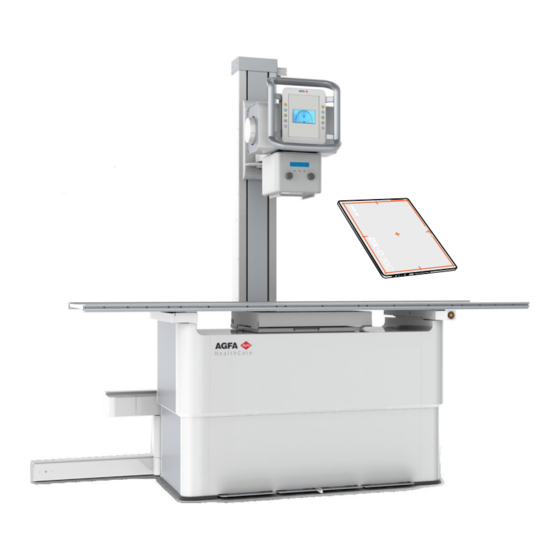
DR 400 | Introduction | 13 Configuration DR 400 is a configurable DR (Direct Radiography X-ray system) or CR (Computed Radiography) X-ray system. The complete DR 400 consists of the following components: • RAD Table with an integrated DX-D Fixed DR Detector or with a bucky. In the bucky a DR Detector or a CR cassette can be inserted. - Page 14 X-ray tube stand mounted on RAD Table X-ray tube with collimator and tube head display Portable DR Detector RAD Table with integrated generator RAD Wall Stand Figure 1: DR 400 configuration for DR Topics: • Applied Parts Applied Parts Applied Parts refer to parts of the medical electrical equipment that in normal use necessarily comes into physical contact with the patient for the equipment to perform its function.
- Page 15 DR 400 | Introduction | 15 • Mattress (optional) • Compression belt (optional) RAD Wall Stand • Front panel of the RAD Wall Stand • Overhead arm support (optional) • Patient hand grips (optional) DR Detector • DR Detector 3231A EN 20150710 1114...
-
Page 16: Equipment Classification
16 | DR 400 | Introduction Equipment Classification Per EN/IEC 60601-1:2005, EN/IEC 60601-2-54:2009, this device is classified as following: Table 1: Equipment classification Class I equipment Equipment in which protection against electric shock does not rely on basic insulation only, but includes a fixed connection to mains power with protective earth conductor. -
Page 17: Options And Accessories
DR 400 | Introduction | 17 Options and Accessories The system is delivered with a set of labels. When using multiple DR Detectors, on the labels a nickname is written to identify the DR Detector. An identical label is attached to the bucky of the X-ray system to identify the dedicated workspace of each DR Detector. -
Page 18: Operation Controls
18 | DR 400 | Introduction Operation Controls Topics: • RAD Table • RAD Wall Stand • Control Panel of the X-Ray Tube Stand • NX Application on the NX Workstation • Software Console • DR Detector Switch • X-ray generator mini console •... - Page 19 DR 400 | Introduction | 19 Figure 3: RAD Wall Stand with vertical bucky Related Links RAD Wall Stand on page 96 Control Panel of the X-Ray Tube Stand Figure 4: Control Panel of the X-Ray Tube Stand with tube head display...
- Page 20 20 | DR 400 | Introduction Tube head display The tube head display can be used to control X-ray exposure parameters. It displays the system status. Last name, first name *June 10, 1960, 08154711032, Chest PA 0.1 mm Cu Detector table 1 mm Al 35°...
- Page 21 DR 400 | Introduction | 21 Figure 8: Software Console DR Detector Switch The DR Detector Switch is available in the device status frame of the Software Console. The DR Detector Switch shows which DR Detector is active and shows its status.
- Page 22 22 | DR 400 | Introduction Meaning Good Low Bad Wired DR Detector DR detector status icon (blinking) Meaning Ready Initializing Error Sleep One DR detector exposure must be selected X-ray generator mini console The X-ray generator mini console is available in the operator room.
- Page 23 DR 400 | Introduction | 23 The X-ray tube is prepared for performing an exposure. Starting the exposure Before starting the exposure: 1. Check if the exposure settings displayed on the console are suitable for the exposure. 2. Check the Ready for Exposure status.
- Page 24 24 | DR 400 | Introduction The collimator provides X-ray filtering using the integrated filters or by inserting a filter in the rails. An integrated DAP meter (Dose Area Product Meter) in the collimator is available as an option. Figure 12: Collimator...
- Page 25 DR 400 | Introduction | 25 Emergency stop button Figure 13: Emergency stop button If a system malfunction causes an emergency situation involving the patient, operating personnel or any system component, activate the emergency stop on the RAD Table. All motor driven movements will be stopped.
- Page 26 26 | DR 400 | Introduction Warning: It must be ensured that the emergency switches are always freely accessible. 3231A EN 20150710 1114...
-
Page 27: System Documentation
• DX-D Software Console, DR Tube Head Display User Manual, document 0389 • User manuals for the supported DR Detectors • DX-D DR Detector Calibration Key User manual, document 0134 Other documentation available on the DR 400 User Documentation CD: • DAP Datasheet • X-ray Tube Documentation • Collimator Datasheet •... -
Page 28: Training
The user must make sure that training is received in accordance with local laws or regulations that have the force of law. Your local Agfa or dealer representative can provide further information on training. The user must note the following information in the system documentation: •... -
Page 29: Product Complaints
If the device malfunctions and may have caused or contributed to a serious injury, Agfa must be notified immediately by telephone, fax or written correspondence to the following address: Agfa Service Support - local support addresses and phone numbers are listed on www.agfa.com Agfa - Septestraat 27, 2640 Mortsel, Belgium... -
Page 30: Compatibility
Compatibility The system must only be used in combination with other equipment or components if these are expressly recognized by Agfa as compatible. A list of such equipment and components is available from Agfa service on request. Changes or additions to the equipment must only be carried out by persons authorized to do so by Agfa. -
Page 31: Compliance
DR 400 | Introduction | 31 Compliance The system is compliant with specific directives and standards. Topics: • General • Safety • Electromagnetic Compatibility • X-Ray Safety • X-Ray Accuracy • Environmental Compliance • Biocompatibility General • The product has been designed in accordance with the MEDDEV... - Page 32 32 | DR 400 | Introduction interference to radio communications. Operation of this equipment in a residential area is likely to cause harmful interference in which case the user will be required to correct the interference at his own expense. If required, contact your local service organization.
-
Page 33: Connectivity
DR 400 | Introduction | 33 Connectivity The NX workstation is connected to the X-ray system to exchange X-ray exposure parameters. The NX workstation requires a 100 Mbit ethernet network to exchange information with a number of other devices. The NX workstation communicates with other devices in the hospital network using one of the following protocols: •... -
Page 34: Installation
34 | DR 400 | Introduction Installation Installation and configuration is performed by an Agfa trained and authorized service engineer. Contact your local support organization for more information. On a configuration with multiple DR Detectors of the same type, it is required to apply labeling to the DR Detector containing a unique nickname for each DR Detector. -
Page 35: Radiation Protection
DR 400 | Introduction | 35 Radiation Protection X-ray radiation can cause serious damage to the health, therefore observe great care and ensure that protection against X-ray exposure is always applied. Some of the effects of X-ray radiation are cumulative and may extend over a period of time. - Page 36 36 | DR 400 | Introduction X-ray room Patient environment Workstation Operator room: protected area Figure 14: Protected area and significant zones of occupancy Warning: The radiation protection has to be applied to the patient. If operator or staff needs to be close to the patient during normal use (e.g.
- Page 37 DR 400 | Introduction | 37 Significant zones of occupancy at the RAD Table 50 cm X-ray tube Focal spot label [—] Significant zone of occupancy. Minimum area 60x60 cm. Minimum height above the floor 200 cm. Dose meter DR Detector or cassette...
- Page 38 38 | DR 400 | Introduction Radiation Protection on page 35 Stray Radiation on page 186 Significant zones of occupancy at the RAD Wall Stand 50 cm Phantom X-ray tube Focal spot label [—] Significant zone of occupancy. Minimum area 60x60 cm.
- Page 39 DR 400 | Introduction | 39 Significant zone of occupancy at the left side of the RAD Table Figure 16: Significant zones of occupancy at the RAD Wall Stand Warning: The radiation protection has to be applied for the patient and for the operator.
-
Page 40: Labels
40 | DR 400 | Introduction Labels Mark Meaning This mark shows compliance of the equipment with Directive 93/42/EEC (for European Union). This mark indicates that this is a Type B Equipment Serial number Manufacturer Date of manufacture Label Meaning... - Page 41 DR 400 | Introduction | 41 • Warning labels on the RAD Wall Stand • Type label • DR Detector identification label • Additional Labeling of the RAD Table • Additional Labeling of the RAD Wall Stand • Labeling of the bucky •...
- Page 42 42 | DR 400 | Introduction Type label Mark Meaning Type label positioned on the lower left hand side of the X-ray tube stand. The type label information for each combination of X-ray tube and X-ray generator is available in the technical data.
- Page 43 DR 400 | Introduction | 43 Additional Labeling of the RAD Table Type label on the lower left hand side of the X-ray tube stand. The type label information for each combination of X-ray tube and X-ray 5521/210 generator is available in the technical data.
- Page 44 44 | DR 400 | Introduction (Sample of subtype 5522/100) This mark indicates that this is a Type B Equipment Functional earth The bucky can be tilted to horizontal position. Do not use the bucky as a seat. A pinch point label is located on top of the tilting extension.
- Page 45 DR 400 | Introduction | 45 Compliance with China RoHS SJ/ T11364-2006. Indication of the Environment Friendly Use Period (EFUP) as the period (years) during which the hazardous substances do not leak or mutate under normal use. The label is located on the rear cover of the bucky or on the bucky drawer below the rotating platform.
-
Page 46: Cleaning And Disinfecting
46 | DR 400 | Introduction Cleaning and Disinfecting All appropriate policies and procedures should be followed to avoid contamination of the staff, patients and equipment. All existing universal precautions should be extended to avoid potential contaminations and to avoid patients coming into (close) contact with the device. The user is responsible for selecting a disinfection procedure. - Page 47 Disinfecting To disinfect the device, use only disinfectants and disinfection methods that are approved by Agfa and that correspond to the national regulation and guidelines as well as explosion protection. If you plan to use other disinfectants, approval of Agfa is needed before use, as most disinfectants can damage the device.
- Page 48 • Using unsuitable disinfectants can cause discoloration and damage of the surface of the equipment. Approved disinfectants Refer to the Agfa website for specifications on the disinfectants that have been found compatible with the cover material of the device and can be used on the outer surface of the device.
-
Page 49: Patient Data Security
DR 400 | Introduction | 49 Patient data security The user must ensure that the patients’ legal requirements are met and that the security of the patient data is guarded. The user must define who can access patient data in which situations. -
Page 50: Maintenance
50 | DR 400 | Introduction Maintenance Always consult the Agfa Service documentation and an AGFA trained and authorized Service engineer for complete maintenance schedules. Topics: • Maintenance • Maintenance of the RAD Table, RAD Wall Stand and X-Ray Tube Stand... - Page 51 DR 400 | Introduction | 51 additions, maintenance or repairs are carried out by an Agfa certified field service engineer. Table 2: Lifetime and maintenance Lifetime Expected lifetime for the X-ray unit 10 years Periodic maintenance The equipment shall have a technical maintenance to...
- Page 52 52 | DR 400 | Introduction Warming-up of X-ray tube The X-ray tube needs to be warmed-up before making X-ray exposures at the start of each day and when the X-ray tube has not been in use for more than an hour.
-
Page 53: Environmental Protection
DR 400 | Introduction | 53 Environmental protection Figure 21: WEEE symbol Figure 22: Battery symbol WEEE end user notice The directive on Waste Electrical and Electronic Equipment (WEEE) aims to prevent the generation of electric and electronic waste and to promote the reuse, recycling and other forms of recovery. -
Page 54: Safety Directions
Warning: To avoid risk of electric shock, this equipment must only be connected to a supply mains with protective earth. Warning: All Agfa medical products must be used by trained and qualified personnel. Warning: Ionizing radiation can lead to radiation injuries if handled incorrectly. - Page 55 DR 400 | Introduction | 55 Warning: Operating the equipment when it is faulty includes the risk of radiological exposure and injury to the patient and to the operator. Operate the equipment only in safe and fault-free conditions. Safety Directions for the X-Ray System...
- Page 56 56 | DR 400 | Introduction Caution: Excessive ambient temperature may impact performance of DR Detectors and cause permanent damage to the equipment. If ambient temperature and humidity is outside the range specified in the technical data, do not operate the system or use air conditioning.
- Page 57 DR 400 | Introduction | 57 Caution: Make sure that the patient hand grips are securely mounted. 3231A EN 20150710 1114...
-
Page 58: Getting Started
58 | DR 400 | Getting started Getting started Topics: • Starting the System • Basic workflow using the DR Detector • Basic workflow using a CR cassette • X-Ray System Positioning • Guidelines for Pediatric Applications • Stopping the System... -
Page 59: Starting The System
DR 400 | Getting started | 59 Starting the System To start the system: Note: Allow the DR Detector to warm up before the system is used for clinical purposes. The warming-up time starts as soon as the DR Detector has been powered on and the NX workstation is running. -
Page 60: Basic Workflow Using The Dr Detector
60 | DR 400 | Getting started Basic workflow using the DR Detector Topics: • Step 1: retrieve the patient info • Step 2: select the exposure • Step 3: prepare the exposure • Step 4: check the exposure settings •... -
Page 61: Step 1: Retrieve The Patient Info
DR 400 | Getting started | 61 Step 1: retrieve the patient info At the NX workstation: 1. When a new patient comes in, define the patient info for the exam. 2. Start the exam. 3231A EN 20150710 1114... -
Page 62: Step 2: Select The Exposure
62 | DR 400 | Getting started Step 2: select the exposure In the operator room: At the NX workstation, select the thumbnail for the exposure in the Image Overview pane of the Examination window. The default X-Ray exposure parameters for the selected exposure are sent to the modality and displayed on the Software Console. -
Page 63: Step 3: Prepare The Exposure
DR 400 | Getting started | 63 Step 3: prepare the exposure In the examination room: 1. Position the DR Detector. When using the bucky, check that the identification labels on the DR Detector and on the bucky match. Do not use a DR Detector that is dedicated to another bucky. -
Page 64: Step 4: Check The Exposure Settings
64 | DR 400 | Getting started Step 4: check the exposure settings Related Links DR Detector Switch on page 21 On the NX application: 1. Check if the DR Detector Switch displays the name of the DR Detector that's being used 2. -
Page 65: Step 5: Execute The Exposure
DR 400 | Getting started | 65 Step 5: execute the exposure In the operator room: Press the exposure button to execute the exposure. Instruction: Make sure the generator is ready for exposure before you press the exposure button. Warning: During exposure ionizing radiation is emitted by the X-ray system. -
Page 66: Step 6: Perform A Quality Control
66 | DR 400 | Getting started Step 6: perform a quality control At the NX workstation: 1. Select the image on which quality control is to be performed. 2. Prepare the image for diagnosis by using e.g. L/R markers or annotations. -
Page 67: Basic Workflow Using A Cr Cassette
DR 400 | Getting started | 67 Basic workflow using a CR cassette Note: Using an ID Tablet to identify cassettes before the exposure will break the communication of X-ray parameters between the NX workstation and the X-ray generator console. It is advised to identify cassettes after the exposure, as described in this workflow. -
Page 68: Step 1: Retrieve The Patient Info
68 | DR 400 | Getting started Step 1: retrieve the patient info At the NX workstation: 1. When a new patient comes in, define the patient info for the exam. 2. Start the exam. 3231A EN 20150710 1114... -
Page 69: Step 2: Select The Exposure
DR 400 | Getting started | 69 Step 2: select the exposure In the operator room at the NX workstation: 1. Select the thumbnail for the exposure in the Image Overview pane of the Examination window. 2. Select CR in the Detector Switch. -
Page 70: Step 3: Prepare The Exposure
70 | DR 400 | Getting started Step 3: prepare the exposure In the examination room: 1. Position the cassette. Note: For a free exposure, partial lead covering of the cassette may be required if multiple images are taken on one cassette. -
Page 71: Step 4: Check The Exposure Settings
DR 400 | Getting started | 71 Step 4: check the exposure settings In the operator room on the Software Console: 1. Check if the exposure settings displayed on the console are suitable for the exposure. 2. Check the Ready for Exposure status. -
Page 72: Step 5: Execute The Exposure
72 | DR 400 | Getting started Step 5: execute the exposure In the operator room: Press the exposure button to execute the exposure. Warning: During exposure ionizing radiation is emitted by the X-ray system. To indicate the presence of ionizing radiation, the radiation indicator on the control console lights up. -
Page 73: Step 6: Repeat Steps 2 To 5 For The Next Subexposures
DR 400 | Getting started | 73 Step 6: repeat steps 2 to 5 for the next subexposures 3231A EN 20150710 1114... -
Page 74: Step 7: Digitize The Image
74 | DR 400 | Getting started Step 7: digitize the image In the examination room: Take the exposed cassette. In the operator room: 1. Insert the cassette in the digitizer. 2. Click ID in the examination window of NX. -
Page 75: Step 8: Perform A Quality Control
DR 400 | Getting started | 75 Step 8: perform a quality control In the operator room at the NX workstation: 1. Select the image on which quality control is to be performed. 2. Prepare the image for diagnosis by using e.g. L/R markers or annotations. -
Page 76: X-Ray System Positioning
76 | DR 400 | Getting started X-Ray System Positioning Topics: • RAD Table Exposures • Oblique Exposures • Lateral Exposures • RAD Wall Stand Exposures 3231A EN 20150710 1114... -
Page 77: Rad Table Exposures
DR 400 | Getting started | 77 RAD Table Exposures 1. Position the patient on the RAD table. 2. Position the X-ray tube stand with the X-ray tube over the patient. The bucky is automatically aligned to the X-ray tube by mechanical coupling. -
Page 78: Oblique Exposures
78 | DR 400 | Getting started Oblique Exposures 1. Position the patient on the RAD Table. 2. Move the X-ray tube stand out of the coupling range of the bucky. 3. Position the bucky under the patient. 4. Set the required angle of the X-ray tube. -
Page 79: Lateral Exposures
DR 400 | Getting started | 79 Lateral Exposures 1. Unlock the X-ray tube arm and rotate 90° around. 2. Rotate the X-Ray tube 90° around. Check the angle on the angle display. 3. Mount the lateral cassette holder on the side rail of the tabletop. Fix it using the two lower screws. -
Page 80: Rad Wall Stand Exposures
80 | DR 400 | Getting started RAD Wall Stand Exposures 1. Adjust the height of the bucky on the RAD Wall Stand. 2. Position the patient in front of the RAD Wall Stand. 3. Move the table top away from the RAD Wall Stand. -
Page 81: Guidelines For Pediatric Applications
DR 400 | Getting started | 81 Guidelines for Pediatric Applications Caution: Children are more radiosensitive than adults. Adopting the Image Gently campaign guidelines and reducing dose for radiographic procedures while maintaining acceptable clinical image quality will benefit patients. Please review the following link and reduce pediatric technique factors accordingly: http://www.pedrad.org/associations/5364/ig/... - Page 82 82 | DR 400 | Getting started • Avoid multiple scans and use alternative diagnostic studies (such as ultrasound or MRI) when possible. 3231A EN 20150710 1114...
-
Page 83: Stopping The System
DR 400 | Getting started | 83 Stopping the System To stop the system: 1. Stop the NX workstation. NX can be stopped in two ways, either by logging out of Windows or without logging out of Windows. For detailed information on stopping NX, refer to the NX User Manual, document 4420. -
Page 84: Operation
84 | DR 400 | Operation Operation Topics: • Tube head display • RAD Table and X-Ray Tube Stand • RAD Wall Stand • Bucky • Grids • Storage box for DR Detector and grids • Automatic Exposure Control (AEC) •... -
Page 85: Tube Head Display
DR 400 | Operation | 85 Tube head display Last name, first name *June 10, 1960, 08154711032, Chest PA Detector table 0.1 mm Cu 1 mm Al 35° Patient information Status bar with exam type Modality position DR Detector Switch... -
Page 86: Rad Table And X-Ray Tube Stand
86 | DR 400 | Operation RAD Table and X-Ray Tube Stand The RAD Table with integrated X-ray tube stand allows X-ray examinations from head to foot of lying or sitting patients. The tube stand has two variants, depending on the side where the tube stand rail is protruding: •... - Page 87 DR 400 | Operation | 87 Control panel of the X-ray tube stand Figure 28: RAD Table with integrated X-ray tube stand, example of left hand version Movement control buttons Tube head display Handle with integrated release button for omni direction movement.
-
Page 88: Positioning The X-Ray Tube Stand
88 | DR 400 | Operation Positioning the X-Ray Tube Stand The operation controls of the X-ray tube stand are located at the control panel. The X-ray tube stand must be positioned by the operator manually. To release the brake for the selected movement direction or rotation, press and hold the button and move the X-ray tube stand. - Page 89 DR 400 | Operation | 89 Rotation of the collimator around the axis of the X-ray beam The standard position of the X-ray tube arm is indicated by markers. When the tube arm is in standard position it is centered in transversal direction on the bucky.
- Page 90 90 | DR 400 | Operation The vertical stop on the tube stand is always active. The two transversal stops are active when the X-ray tube is rotated towards the wall stand (90°+/- 10°). To enter a stop position, move the X-ray tube stand or the X-ray tube arm in longitudinal or vertical direction.
-
Page 91: Positioning The Rad Table
DR 400 | Operation | 91 Positioning the RAD Table There are two versions of the RAD table: • Fixed height RAD Table with a height of 70 cm • Elevating RAD Table with adjustable height from 55 cm to 90 cm The movements of the RAD table are controlled by foot pedals mounted at front side of the table. - Page 92 92 | DR 400 | Operation Foot pedal to raise table height (maximum 90 cm). When minimum or maximum position of the table is reached, the movement is stopped automatically. When the standard exposure height (70 cm) is reached, the movement is stopped automatically.
-
Page 93: Positioning The Bucky
DR 400 | Operation | 93 Positioning the Bucky The bucky center position is automatically aligned to the position of the X-ray tube stand. The mechanical coupling between the bucky and the X-ray tube stand is active within the travel range of the bucky. -
Page 94: Rad Table Accessories
94 | DR 400 | Operation RAD Table Accessories Caution: Using wrong accessories that cannot be properly attached to the system can lead to hazardous situations and injury. Use only original accessories provided by the manufacturer. Topics: • Mounting the patient hand grips •... - Page 95 DR 400 | Operation | 95 Note: The collision protection is influenced by the patient weight. Take special care when moving the RAD Table with a patient lying on. Figure 35: Location of the collision protection accessories Other RAD Table accessories On request further accessories for the RAD table are available: •...
-
Page 96: Rad Wall Stand
96 | DR 400 | Operation RAD Wall Stand The RAD Wall Stand allows vertical X-ray exposures of patients standing or sitting in front of the RAD Wall Stand. The wall stand has two variants: • wall stand with vertical bucky, supporting vertical movement (up and down) •... - Page 97 DR 400 | Operation | 97 Vertical movement handle (both sides) Tilting extension Tilting handle Figure 38: RAD Wall Stand, vertical version and vertical tilting version Caution: The format indications on the front panel show the format of the cassette or detector. Take into account that the actual area for imaging is smaller than indicated.
-
Page 98: Positioning The Rad Wall Stand
98 | DR 400 | Operation Positioning the RAD Wall Stand Vertical movement handle with brake switch Tilting angle scale Tilting handle Figure 39: Positioning controls Warning: Maintain visual contact with the patient while moving the equipment close to the patient in order to detect hazardous situations (e.g. - Page 99 DR 400 | Operation | 99 Caution: The maximum load for the bucky movement in vertical direction is 20 kg. The bucky may slip downward when applying excessive load. Note: Do not move the bucky with excessive force to the end stop positions.
- Page 100 100 | DR 400 | Operation The X-ray tube stand is moving up or down accordingly. Note: The movement of the X-ray tube is automatically stopped if the distance between the X-ray tube head and the table top would become too small (less than 10 cm).
-
Page 101: Rad Wall Stand Accessories
DR 400 | Operation | 101 RAD Wall Stand Accessories Caution: Using wrong accessories that cannot be properly attached to the system can lead to hazardous situations and injury. Use only original accessories provided by the manufacturer. Topics: • Patient hand grips •... - Page 102 102 | DR 400 | Operation Caution: Do not insert the handle oriented parallel to the bucky. The handle may collide with the Wall Stand column. Caution: Take care of the overhead handle position when tilting the bucky. To mount and position the overhead handle: 1.
- Page 103 DR 400 | Operation | 103 Stand under the head cover and then fixed to a wall. It has to be installed by service. Other RAD Wall Stand accessories On request further accessories for the RAD Wall Stand is available: •...
-
Page 104: Bucky
104 | DR 400 | Operation Bucky The bucky is installed in RAD table and RAD wall stand. The bucky clamps the cassette or detector during exposure and centers them relative to the Automatic Exposure Control (AEC) and the grid. - Page 105 DR 400 | Operation | 105 • Bucky configuration • Rotating the bucky • Loading of the bucky in the RAD Table • Loading of the bucky in the RAD Wall Stand • Unloading of the bucky in the RAD Table •...
-
Page 106: Bucky Configuration
106 | DR 400 | Operation Bucky configuration Cassette only configuration The workflow with cassettes requires removing the cassette from the bucky after each exposure. The cassette has to be scanned using a digitizer to get the final image. The correct orientation of the cassette is applied by the way it is inserted in the bucky and there is no need to use the rotation mechanism. - Page 107 DR 400 | Operation | 107 Function Bucky with Bucky with Bucky for fixed tray for tray for DR detector multiple multiple cassette or cassette or detector detector formats formats RAD Table 5523/100 5523/120 5523/300 RAD Wall Stand, 5523/200 5523/220...
- Page 108 108 | DR 400 | Operation Indicators for large format cassette or detector position to the top of the bucky Large format detector positioned to the top of the bucky Figure 46: Wall stand bucky with large format detector positioned to the top...
-
Page 109: Rotating The Bucky
DR 400 | Operation | 109 Rotating the bucky The cassette or detector in the bucky can be rotated without removing it from the clamping. To change the orientation of the cassette or detector in the bucky: 1. Open the bucky drawer halfway by pulling the front handle. -
Page 110: Loading Of The Bucky In The Rad Table
110 | DR 400 | Operation Loading of the bucky in the RAD Table To load the bucky with a cassette or detector: 1. Open the bucky drawer completely by pulling the front handle. 2. Push the cassette or detector towards the rear slider to open the clamping mechanism wide enough to contain the cassette or detector. -
Page 111: Loading Of The Bucky In The Rad Wall Stand
DR 400 | Operation | 111 Loading of the bucky in the RAD Wall Stand To load the bucky with a cassette or detector: 1. Open the bucky drawer completely by pulling the front handle. 2. Rotate the drawer to portrait orientation. -
Page 112: Unloading Of The Bucky In The Rad Table
112 | DR 400 | Operation Unloading of the bucky in the RAD Table To unload the bucky with a cassette or detector: 1. Open the bucky drawer completely by pulling the front handle. 2. Push firmly with both hands the cassette or detector towards the rear clamp to open the clamping mechanism. -
Page 113: Unloading Of The Bucky In The Rad Wall Stand
DR 400 | Operation | 113 Unloading of the bucky in the RAD Wall Stand To unload the bucky with a cassette or detector: 1. Open the bucky drawer completely by pulling the handle. 2. Rotate the carrier back to portrait position. -
Page 114: Centering And Collimating
114 | DR 400 | Operation Centering and collimating Depending on the format of the cassette or detector inside the bucky and the body part to expose, collimation and centering of the X-ray field have to be applied before exposure. - Page 115 DR 400 | Operation | 115 The ACSS functionality of the bucky is only available in combination with the automatic collimator Ralco 225 ACS. The ACCS functionality is not available when the collimator is in manual mode. Related Links Automatic collimator...
-
Page 116: Orientation Of Dx-D 10C, Dx-D 10G In The Bucky
116 | DR 400 | Operation Orientation of DX-D 10C, DX-D 10G in the bucky To avoid damage to the cable of the detector, there are restrictions on the orientation of the detector when loading the bucky. Caution: Inserting DX-D 10C, DX-D 10G using other orientations than described will damage the cable when closing the bucky or when rotating the carrier. - Page 117 DR 400 | Operation | 117 Orientation in the RAD Wall Stand right loading • To use the detector landscape orientation, insert the detector in landscape mode with the cable at upper right hand side. • To use the detector in portrait orientation: 1.
-
Page 118: Grids
118 | DR 400 | Operation Grids Anti-scatter grids are used to reduce scattered radiation and improve image quality. Grids are available as an option. For DR Detectors focused grids are used. Focused grids require centering of the X-ray source to the detector and a specific distance range between X-ray source and detector. -
Page 119: Grid Focal Distance Color Indication
DR 400 | Operation | 119 Grid focal distance color indication The handle of the grid is visible when the grid is inserted and its color indicates the focal distance of the grid. Focal Distance Color 100 cm 150 cm... -
Page 120: Grid Detection
120 | DR 400 | Operation Grid detection The grid detection functionality of the bucky detects the type and position of the inserted grid. The grid status is shown on the tube head display and on the Software Console. 3231A EN 20150710 1114... -
Page 121: Storage Box For Dr Detector And Grids
DR 400 | Operation | 121 Storage box for DR Detector and grids The storage box provides vertical storage space for a DR Detector and up to three grids. It can be mounted to the wall or stand on a stable surface. -
Page 122: Automatic Exposure Control (Aec)
122 | DR 400 | Operation Automatic Exposure Control (AEC) The use of an AEC ensures optimal and reproducible image quality independent of the radiation, the object exposed or other factors. The AEC has three sensor elements (ionization chambers) The AEC is mounted in the bucky of RAD Table and RAD Wall Stand between the grid and the detector or cassette. -
Page 123: Manual Collimator
DR 400 | Operation | 123 Manual Collimator The Collimator can rotate ± 90° on its vertical axis while the X-ray tube remains in the same position. This movement is performed by manually turning the collimator and has detents every 90°. - Page 124 124 | DR 400 | Operation cable connecting the radiation meter to the generator 2. Unscrew the screw on the left hand side of the rail system. 3. Pull out the radiation meter. The DAP meter is calibrated during production to be used up to 2000 m altitude.
-
Page 125: Automatic Collimator
DR 400 | Operation | 125 Automatic Collimator The collimator can limit the collimated area to the size of the cassette or DR Detector inserted in the bucky. Display • Size of the collimated area • Active filter Operation mode indicators •... - Page 126 126 | DR 400 | Operation • Dose Area Product Meter (DAP) 3231A EN 20150710 1114...
-
Page 127: Semi-Automatic Collimation Mode
DR 400 | Operation | 127 Semi-automatic collimation mode The semi-automatic collimation mode is activated if any of following conditions applies: • the collimator is rotated by more than +/-3° • the tube head unit is rotated by more than +/-3° from the center position •... -
Page 128: Manual Collimation Mode
128 | DR 400 | Operation Manual collimation mode The manual collimation mode is activated when the user turns the key at the backside of the collimator. The yellow indicator at front of collimator is lit and an open key lock is displayed in the lower left corner of the collimator display. -
Page 129: Dose Area Product Meter (Dap)
DR 400 | Operation | 129 Dose Area Product Meter (DAP) An integrated DAP meter (Dose Area Product Meter) in the collimator is availabe as an option. The DAP meter reads the radiation as Dose Area Product in [µGy x m The measured radiation value is transferred to the Software Console automatically and displayed after each exposure. -
Page 130: Effect Of Sid On Patient Dose
130 | DR 400 | Operation Effect of SID on patient dose Changing the distance of the X-ray tube to the patient affects the dose applied to the patient. For example doubling the distance reduces the dose by a factor of 4. The new dose can be calculated by a formula: new mAs = known mAs ×... -
Page 131: X-Ray Generator Console
DR 400 | Operation | 131 X-Ray Generator Console The X-ray generator console is limited in functionality to power on and power off the generator and to connect the DR Generator Sync with the exposure hand switch to trigger the exposure. -
Page 132: Starting And Stopping The Generator
132 | DR 400 | Operation Starting and stopping the generator The generator is switched on and off by the power buttons on the X-ray generator mini console. Press the Power ON button on the X-ray generator control box to switch on the generator. -
Page 133: X-Ray Tube Start-Up Modes
DR 400 | Operation | 133 X-ray tube start-up modes The system can make exposures using two start-up modes, when pressing the exposure button in preparation stage: • Low speed start-up that boosts the tube anode to ca. 3000 rpm. -
Page 134: X-Ray Generator Messages And Warning Signals
134 | DR 400 | Operation X-ray generator messages and warning signals Acoustic signals The generator indicates particular states with acoustic signals: • Exposure is terminated: 500 ms tone • Errors: rapid series of tones Visual signals The generator indicates particular states with visual signals: •... - Page 135 DR 400 | Operation | 135 X-ray generator errors Follow the instructions for each specific error. Never open the machine. The table contains an action for each error. Notify service Notify service on frequent occurrence Can be eliminated by operator...
- Page 136 136 | DR 400 | Operation Error Display Explanation Action number receive timeout Serial interface receipt timeout 2 E²Prom wait timeout E2PROM access timeout fillament system Heater fault DAP system Area dose measuring system self test error filament parameter Deviating heating parameters...
- Page 137 DR 400 | Operation | 137 Error Display Explanation Action number dose too low after Dose too small after 50 ms 50ms (automatic exposure control) pulse delay too long Exposure pause between 2 pulses > 2 sec (automatic exposure control) exp.
- Page 138 138 | DR 400 | Operation Error Display Explanation Action number CAN system CAN bus transfer error BUS system CAN bus transfer is highly interfered or interrupted SCB transfer Storz bus system timeout timeout SCB false version Storz bus version error...
-
Page 139: Exposure Parameters
DR 400 | Operation | 139 Exposure parameters Tube Voltage The tube voltage can be selected in steps of 1 kV in the range of 40 to 150 kV. mAs Product Step Step Step Step 0.63 Tube current [mA] Step... - Page 140 140 | DR 400 | Operation Step mA Step (only for generator with 50 kW power or higher) (only for generator with 65 kW power or higher) Exposure time [ms] Step Step Step Step 1250 1600 2000 2500 3200 4000...
- Page 141 DR 400 | Operation | 141 HFe 401 HFe 501 HFe 601 HFe 801 (40 kW) (50 kW) (65 kW) (80 kW) HSS: 400 mA HSS: 500 mA E7869XX HSS: 650 mA HSS: 800 mA • LSS: Low Speed Start option •...
-
Page 142: Problem Solving
142 | DR 400 | Problem solving Problem solving Topics: • System messages • Restoring connection between generator and NX after generator failure • Automatic collimation always too wide or too narrow • Empty Bucky Failure, Double Exposure Failure •... -
Page 143: System Messages
DR 400 | Problem solving | 143 System messages The system can display messages to the user on the screen. • Software Console • Message frame Click the message frame to view older messages. • Dialog box The software console displays a dialog box in the middle of the screen. - Page 144 Messages that require no user response disappear automatically. Warning or error messages may instruct to contact the Agfa service organization if the problem repeats, but by following the instructions in the message, the user can restore the operation of the system.
-
Page 145: Restoring Connection Between Generator And Nx After Generator Failure
DR 400 | Problem solving | 145 Restoring connection between generator and NX after generator failure Details An error on the generator occurred. NX lost connection to the generator. An error message that no connection with the generator can be established is displayed on the Software Console. -
Page 146: Automatic Collimation Always Too Wide Or Too Narrow
146 | DR 400 | Problem solving Automatic collimation always too wide or too narrow Details The collimated area is not adapted correctly to the size of the cassette or DR Detected inserted in the bucky. Cause The sensors in the bucky that detect the size of the cassette or DR Detector are dirty or have become weak. -
Page 147: Empty Bucky Failure, Double Exposure Failure
DR 400 | Problem solving | 147 Empty Bucky Failure, Double Exposure Failure Details The exposure button was pressed but no exposure was performed. No radiation icon is displayed. The preparation icon is displayed. • CR: Error message 40 is displayed on the Software Console. - Page 148 148 | DR 400 | Problem solving NX does not connect to the generator due to ID tablet Details This occurs on a DR installation in combination with a digitizer using an ID Tablet. The NX application and the Software Console cannot connect to the generator.
-
Page 149: No Table Movement
DR 400 | Problem solving | 149 No table movement Details The table is not moving up or down when pressing the foot pedals with double click. No error is shown. Cause One of the foot pedals was pressed longer than 90 seconds. -
Page 150: Dr Detector Is Exceeding The Maximum Working Temperature
150 | DR 400 | Problem solving DR Detector is Exceeding the Maximum Working Temperature Details A message is displayed on NX indicating that the DR Detector is exceeding the maximum working temperature. Cause Due to ambient temperature conditions and the number of acquired images, the DR Detector’s internal... -
Page 151: Dr Detector Must Be Recalibrated
DR 400 | Problem solving | 151 DR Detector must be Recalibrated Details A message is displayed on NX indicating that the DR Detector must be recalibrated. Cause A DR Detector must be recalibrated at regular interval. Brief Solution Follow the instructions in the DR System Key User Manual to calibrate the DR Detector: •... -
Page 152: Technical Data
152 | DR 400 | Technical Data Technical Data Topics: • DR 400 Technical Data • Generator Technical Data • RAD Table and X-Ray Tube Stand Technical Data • RAD Wall Stand Technical Data • X-Ray Tube Technical Data •... -
Page 153: Dr 400 Technical Data
DR 400 | Technical Data | 153 DR 400 Technical Data Manufacturer Agfa HealthCare N.V. Septestraat 27 2640 Mortsel, Belgium Type 5520/XXX Power line 400 V Y- 400V 3N~ PE (Y) 50/60 Hz source Power line 400/480 V 400/480V 3~PE (delta without N) 50/60Hz... -
Page 154: Environmental Conditions
154 | DR 400 | Technical Data (+ 0.2 mm Al with DAP meter integrated in the collimator) Environmental conditions Environmental Conditions (during storage and transport) Temperature (ambient) between -15° and 50° Celsius Humidity (non condensing) between 15 and 90 % relative humidity... -
Page 155: Generator Technical Data
DR 400 | Technical Data | 155 Generator Technical Data Manufacturer Spellman High Voltage Electronics GmbH Josef-Baumann-Strasse 23 D-44805 Bochum, Germany Supported EDITOR HFe EDITOR HFe EDITOR HFe EDITOR HFe Models Max. Power 40 kW 50 kW 65 kW 80 kW... - Page 156 156 | DR 400 | Technical Data The values for Power Output represent the maximum power output of the X- ray generator. These values do not represent the available exposure parameter settings on the Software Console. Related Links Exposure parameters...
-
Page 157: Rad Table And X-Ray Tube Stand Technical Data
DR 400 | Technical Data | 157 RAD Table and X-Ray Tube Stand Technical Data Manufacturer Agfa HealthCare N.V. Septestraat 27 2640 Mortsel, Belgium Type TS-Fix-L-001 5521/100 TS-Fix-R-001 5521/110 TS-Elev-L-001 5521/200 TS-Elev-R-001 5521/210 TS-Fix-L-002 5521/300 TS-Fix-R-002 5521/310 TS-Elev-L-002 5521/400 TS-Elev-R-002... -
Page 158: Movement Ranges
158 | DR 400 | Technical Data Minimum room height 245 cm Tabletop attenuation equivalent ≤ 0.7 mm Aluminum According to DIN EN 60601-1-3 with 100kV and HVL 3.6 mm Al FDA 21 CFR § 1020.30 (n) with 100kV and HVL 3.6 mm Al... - Page 159 DR 400 | Technical Data | 159 Rotation of the collimator ±90° around the axis of the X-ray Caution: Rotation may be beam limited by cables. Avoid strain on the cables during rotation. 3231A EN 20150710 1114...
-
Page 160: Rad Wall Stand Technical Data
160 | DR 400 | Technical Data RAD Wall Stand Technical Data Manufacturer Agfa HealthCare N.V. Septestraat 27 2640 Mortsel, Belgium Type WS-Manual-001 5522/100 WS-Manual-T-001 5522/200 WS-Manual-002 5522/300 WS-Manual-T-002 5522/400 Dimensions Vertical RAD Wall Stand 65.1 cm x 36.7 cm x 224.5 cm... - Page 161 DR 400 | Technical Data | 161 Vertical RAD Wall Stand 157 kg Vertical and tilting RAD Wall 196 kg Stand Maximum load on the bucky 32 kg Maximum load on the brakes for 250 N the vertical movement (*) specific values do not apply as technical data of the system in China...
-
Page 162: X-Ray Tube Technical Data
162 | DR 400 | Technical Data X-Ray Tube Technical Data Manufacturer Toshiba Electron Tubes & Devices Co., Ltd. 1385 Shimoishigami Otawara-Shi, Tochigi-Ken 324-8550 Japan E7884X X-ray Tube 12º 150 kVp dual focal spots 0.6 and 1.2 mm 300 KHU... - Page 163 DR 400 | Technical Data | 163 150 kVp dual focal spots 0.6 and 1.2 mm 600 KHU LS 21/53 kW (50Hz) 23/58 kW (60Hz) HS 40/100 kW (180Hz) 14,49x10 mAh@150kVp maximum load 3231A EN 20150710 1114...
-
Page 164: Bucky Unit Technical Data
164 | DR 400 | Technical Data Bucky Unit Technical Data Manufacturer Agfa HealthCare N.V. Septestraat 27 2640 Mortsel, Belgium Type BT-Cassette-T-001 5523/100 BT-Cassette-T-ACSS-001 5523/120 BT-Cassette-WS-L-001 5523/200 BT-Cassette-WS-ACSS-L-001 5523/220 BT-Cassette-WS-R-001 5523/250 BT-Cassette-WS-ACSS-R-001 5523/270 BT-Fixed-T-001 5523/300 BT-Fixed-WS-L-001 5523/310 BT-Fixed-WS-R-001 5523/320 Dimensions Dimensions in RAD Table 65.5 cm x 60.0 cm x 8.0 cm... - Page 165 DR 400 | Technical Data | 165 (type 5523/100, 5523/200, 5523/250, 5523/300, 5523/310, 5523/320) Operating voltage 24 VDC Operating current 80 mA Electrical connection (type 5523/120, 5523/220, 5523/270) Operating voltage 24 VDC Operating current 375 mA Supported sizes Supported sizes...
-
Page 166: Automatic Exposure Control (Aec) Technical Data
166 | DR 400 | Technical Data Automatic Exposure Control (AEC) Technical Data Manufacturer VacuTec Messtechnik GmbH Dornblüthstrasse 13 D-01277 Dresden, Germany Supported Type No. 145 00 44 Description 3-field chamber with electronics Exposure dose range 1 to 100 uGy... -
Page 167: Ralco R221 Collimator Technical Data
DR 400 | Technical Data | 167 Ralco R221 Collimator Technical Data Manufacturer Ralco Via dei Tigli 13/G 20853 Biassono (MB), Italy Supported type R 221 Maximum radiation leakage 150 kVp – 4 mA Inherent filtration 2 mm Aluminum equivalent... -
Page 168: Ralco R225 Acs Collimator Technical Data
168 | DR 400 | Technical Data Ralco R225 ACS Collimator Technical Data Manufacturer Ralco Via dei Tigli 13/G 20853 Biassono (MB), Italy Supported type R 225 ACS Maximum radiation leakage 150 kVp – 4 mA Inherent filtration 2 mm Aluminum equivalent... -
Page 169: Dose Area Product Meter (Dap) Technical Data
DR 400 | Technical Data | 169 Dose Area Product Meter (DAP) Technical Data Manufacturer VacuTec Messtechnik GmbH Dornblüthstrasse 13 D-01277 Dresden, Germany Supported Type VacuDAP 2004 Dose area product range (0.1 to 3x10 ) µGy x cm Attenuation 0.44 mm Al equivalent (70 kV) Quality filtration 0.24 mm Al equivalent (70 kV) -
Page 170: Dx-D Fixed Dr Detector Technical Data
170 | DR 400 | Technical Data DX-D Fixed DR Detector Technical Data Manufacturer Manufacturer DR Detector Varian X-Ray Products, 1678 So. Pioneer Rd, Salt Lake City, UT 84104, USA Supported models 4343R (part number 7965) CsI conversion screen 4343R (part number 7964) - Page 171 DR 400 | Technical Data | 171 Reliability Estimated product life (if regularly 100 000 RAD serviced and maintained according to Agfa instructions) 3231A EN 20150710 1114...
-
Page 172: Portable Dr Detector Technical Data
172 | DR 400 | Technical Data Portable DR Detector Technical Data Refer to the DR Detector User Manual. 3231A EN 20150710 1114... -
Page 173: Nx Workstation Technical Data
DR 400 | Technical Data | 173 NX Workstation Technical Data Electrical connection Operating voltage 90 – 263VAC Mains fuse protection 5.5A Mains frequency 47 – 63 Hz Power consumption Maximum power consumption 320W 3231A EN 20150710 1114... -
Page 174: Dr Generator Sync Box Technical Data
174 | DR 400 | Technical Data DR Generator Sync Box Technical Data Model name DR Generator Sync Box Type number 5400/516 Labeling Dimensions Depth 21.5 cm Width 33.5 cm Height 6.5 cm Weight 3.2 kg Electrical connection 100-240 V AC, 50/60 Hz Power consumption 40 W (max. -
Page 175: Remarks For Hf-Emission And Immunity
DR 400 | Remarks for HF-emission and immunity | 175 Remarks for HF-emission and immunity Topics: • Remarks for HF-emission and immunity • Essential performance • Cables, transducers and accessories 3231A EN 20150710 1114... -
Page 176: Remarks For Hf-Emission And Immunity
Table 6: Guidance and manufacturer’s declaration – electromagnetic emissions The DR 400 system is intended for use in the electromagnetic environment specified below. The customer or the user of the DR 400 system should assure that it is used in such an environment. Emission test... - Page 177 IEC 61000-3-3 This DR 400 system is intended for operation in the electromagnetic environment given below. The user of the DR 400 system should ensure that it is used in such an environment. Table 7: Guidance and manufacturer’s declaration – electromagnetic...
- Page 178 Table 8: Guidance and manufacturer’s declaration – electromagnetic immunity The DR 400 system is intended for use in the electromagnetic environment specified below. The customer or the user of the DR 400 system should assure that it is used in such an environment. Immunity test...
- Page 179 DR 400 | Remarks for HF-emission and immunity | 179 Use portable and mobile radio sets at a safe distance from the device (including the leads) not closer than the recommended protective distance, which is calculated according to the equation suitable for the transmission frequency.
- Page 180 Table 9: Recommended separation distances between portable and mobile RF communications equipment and the DR 400 system The DR 400 system is intended for use in an electromagnetic environment in which radiated RF disturbances are controlled. The customer or the user of...
- Page 181 DR 400 | Remarks for HF-emission and immunity | 181 power of transmitter 150 kHz to 80 80 MHz to 800 800 MHz to 2.5 d = 1.2 d = 1.2 d = 2.3 0.01 0.12 0.12 0.23 0.38 0.38 0.73...
-
Page 182: Essential Performance
182 | DR 400 | Remarks for HF-emission and immunity Essential performance EUT-specific compliance criteria considering Essential Performance of Equipment under Test: • No error messages on panel and on display of EUT • No unintended move of table, wall stand and tube-head during mode X- Ray and Standby / no interruption during “Move”... -
Page 183: Cables, Transducers And Accessories
DR 400 | Remarks for HF-emission and immunity | 183 Cables, transducers and accessories Cables, transducers and accessories which were tested and found to comply with the collateral standard IEC60601-1-2 (EMC): Caution: Using cables and accessories not mentioned in this... - Page 184 184 | DR 400 | Remarks for HF-emission and immunity from type maximum remark length 24V, light push button, duple exposure protection) table output wall stand 3 x AWG18 20 m mandatory terminal (230 input terminal (1.0 mm table output...
-
Page 185: For Type 5520/200 Only
DR 400 | Remarks for HF-emission and immunity | 185 For type 5520/200 only from type maximum remark length table output wall stand input 9 pin sub D 20 m shielded terminal terminal (CAN) Optional from type maximum remark length... -
Page 186: Stray Radiation
186 | DR 400 | Stray Radiation Stray Radiation S1,S2 S4,S5 Kerma [uGy] • S1,S2: 100 kV; SID 110 cm; tube/detector centre height 140cm over floor • S3: 100 kV; SID 100 cm; table height of 70 cm (standard working height) •...
Need help?
Do you have a question about the DR 400 and is the answer not in the manual?
Questions and answers