Table of Contents
Advertisement
Quick Links
Model
POWER
QUICK SET
TIME
FILE SEL
ON
OFF
SHIFT
TC SET
DRV,PAT
CONTRAST
AUX
ST
C2
MONO
C1
L/M
MS
R/S
PD204 LOCATION RECORDER
MONITOR
MIN
MAX
PHONES
LOCATION RECORDER
PD204
space
ABC
ENTER
YES
LIGHT
EXIT
1
2
GHI
JKL
BATT
MENU
4
5
PQRS
TUV
ACCESS
HDD
DVD
7
8
Owner's Manual
CUE
DEF
LOCATE
FILE
3
PREV
CUE
NEXT
MNO
CLEAR
PRE REC
JAM
SLATE
6
TONE
WXYZ
symbol
ON
OFF
OFF
MIC
9
0
CIRCLE TAKE
PAUSE
REC
FALSE START
Advertisement
Chapters
Table of Contents

Related Manuals for Fostex PD204


Summary of Contents for Fostex PD204
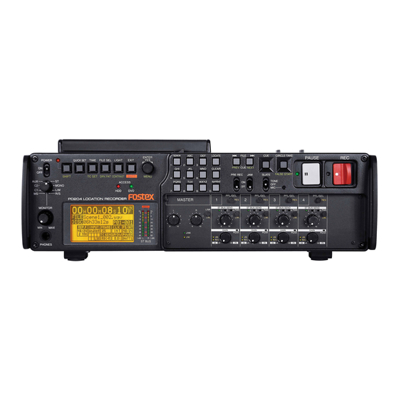
- Page 1 Model ENTER POWER QUICK SET TIME FILE SEL LIGHT EXIT SHIFT TC SET DRV,PAT CONTRAST BATT MENU ACCESS MONO PD204 LOCATION RECORDER MONITOR PHONES Owner’s Manual PD204 space LOCATE FILE PREV NEXT CLEAR PRE REC PQRS WXYZ symbol CIRCLE TAKE...
- Page 2 11. Grounding or Polarization - The precautions that should be taken so that the grounding or polarization means of an appliance is not defeated. Location Recorder Model PD204 CAUTION: TO PREVENT ELECTRIC SHOCK, MATCH WIDE BLADE OF PLUG TO WIDE SLOT, FULLY INSERT.
-
Page 3: Important Safety Instructions
Location Recorder Model PD204... -
Page 4: Table Of Contents
Precautions of installation ...13 Chapter-1: Main features ...15 Main features and functions ...16 What is in the box? ...19 PD204 options and related Fostex products ...19 Chapter-2: Preparation before using the PD204 ...21 Preparation of power supply ...22 Mounting the battery ...23 Important settings for using the battery ...24... - Page 5 Digital audio output connection ...65 Time code output connection ...65 Word clock output connection ...65 Other connections ...66 USB keyboard connection ...66 PC connection ...68 External controller connection ...68 Power connection ...69 Safety Instructions/Table of contents Location Recorder Model PD204...
- Page 6 Selecting the TC frame rate ...90 Selecting the TC generator mode (TC recording mode) ...90 Automatic record start by external time code ...91 Setting the time code output ...91 Force jam to external time code ...92 Location Recorder Model PD204...
- Page 7 Selecting source drive ...110 Making file copy ...111 Dual drive recording ...113 Formatting in the “DDR” mode ...113 Making dual drive recording ...115 Data export to PC ...116 Connecting PC to the unit ...117 Safety Instructions/Table of contents Location Recorder Model PD204...
- Page 8 Safety Instructions/Table of contents How to unmount the PD204 from the PC ...117 Example of copying data to a computer hard disk ...118 Example of exporting data to a computer application ...118 Chapter-7: Creating and editing ALE files (EDIT EDL FILE menu) ...121 Creating a new ALE file ...122...
- Page 9 Restoring a deleted audio file [Restore Del. file] ...197 Formatting a disk (or a hard disk partition) [Format] ...198 Editing the reel number (Volume label) [Reel No.] ...202 Record protection On/Off setting [Rec protect] ...203 Safety Instructions/Table of contents Location Recorder Model PD204 ...170...
- Page 10 Partition protection On/Off setting [Part. protect] ...205 HDD operating time display [HDD Ope. Time] ...206 LOAD SETUP menu ...207 SAVE SETUP menu ...208 Chapter-9: Specifications ...209 Inputs/outputs ...210 Recording/playback ...211 General ...211 Physical dimensions ...212 Block diagram ...213 INDEX ...214 Location Recorder Model PD204...
-
Page 11: Introduction Of This Manual
So you can refer to this chapter as index for detail information. "Chapter 2: Preparations before using the PD204" contains the necessary information when using the PD204 for the first time, such as "About power supply" and "Initial format of a DVD-RAM disk". Precautions •... - Page 12 The unit contains the internal lithium battery for running the internal clock. The battery should be replaced approximately every five years. To replace the battery, ask your dealer or the nearest FOSTEX service station. If the battery is not correctly replaced, there may be a risk of explosion, etc.
-
Page 13: Cautions For Use
In such a case, leave the unit for a while until it warms up and evaporates any moisture. OPEN LOCK DISC PANEL LINE DIGITAL DC-IN DC-OUT 1:GND 1:GND 2:NC 2:NC 3:NC 3:NC 4:12-24V 4:12-24V 1:GND 2:HOT 3:COLD Location Recorder Model PD204 Introduction... - Page 14 Introduction Location Recorder Model PD204...
-
Page 15: Chapter-1: Main Features
Chapter 1: Main features Chapter 1: Main features Location Recorder Model PD204... -
Page 16: Main Features And Functions
4.7GB, non-cartridge DVD-RAM, DVD-R or DVD-RW disk (only a DVD-RAM disk can be used for direct recording). 12-cm DVD combo drive For the optional hard disk drive unit for replacement, ask your local Fostex dealer or service station. Location Recorder Model PD204... - Page 17 TIME CODE IN/OUT connectors AUX IN WORD/VIDEO IN and WORD OUT connectors DIGITAL ANALOG OUT DC-IN 1:GND 2:NC 0 ( A 3:NC 4:12-24V USB port Location Recorder Model PD204 Chapter 1: Main features DC-OUT 1:GND 2:NC 3:NC 4:12-24V 1:GND 2:HOT 3:COLD...
- Page 18 In 24-bit mode, you can make recording with sampling frequencies of 44.1/ 48 kHz, 88.2 kHz, 96 kHz, 176.4 kHz and 192 kHz. In 16-bit mode, you can make recording with sampling frequencies of 44.1 kHz and 48 kHz. Location Recorder Model PD204 Mixer section...
-
Page 19: What Is In The Box
PD204 options and related Fostex products The following PD204 options and related products are available. Ask your local Fostex dealer or sale office for details about them such as prices, specifications, etc. You can also get product information from our web site below. - Page 20 Chapter 1: Main features Location Recorder Model PD204...
-
Page 21: Chapter-2: Preparation Before Using The Pd204
Chapter 2: Preparation before using the PD204 This chapter explains what you should do before using the PD204 for the first time, including power connection, internal clock setting and preparation of the DVD-RAM disk. It also explains how to replace the internal hard disk drive. -
Page 22: Preparation Of Power Supply
PD204 without any special parts, however, the holder projects from the PD204 body. If you want to mount the NP-1 battery housed in the dedicated holder to the PD204 without projecting from the PD204 body, the optional mounting hardware (Model EX-BP1) is needed. -
Page 23: Mounting The Battery
<Note>: If you use the IDX ENDURA battery, read the operation manual supplied with the battery and handle it correctly. The PD204 does not provide battery charge func- tion. Charge the IDX ENDURA battery correctly according to the battery manual. -
Page 24: Important Settings For Using The Battery
• When you use PowerLink batteries, use batteries of the same charging condition. If the charging conditions are significantly different, the PowerLink function may not operate correctly resulting the PD204 powered off. • You cannot mount more than two batteries. Each battery mount can accept up to two batteries. -
Page 25: Power Supply Priority Setting (Essential When Using Both [Dc-In] And A Battery)
The protector can protect the IDX ENDURA-7 and ENDURA-7S. When you <Note>: use the ENDURA-10 or ENDURA-10S, or PowerLink is active, we recommend using the PD204 horizontally. Chapter 2: Preparation before using the PD204 Protector [ADJUST] levers Location Recorder Model PD204... -
Page 26: Saving The Battery Power
Chapter 2: Preparation before using the PD204 Saving the battery power The PD204 offers the following measures for saving the battery power to extend the battery life. • Pressing the [STOP] key stops the disk rotation to save the power consumption. -
Page 27: Dismounting The Battery
PD204. <Note>: Dispose the used battery properly (see the instruction manual of your battery). Keep the removed battery away from children. Chapter 2: Preparation before using the PD204 Eject lever on the PD204 Eject lever on the PD204 Release button... -
Page 28: Using [Dc-In] (Connecting The Ac Adaptor)
You can connect the AC adaptor or another appropriate power source to the [DC IN] connector on the left side panel of the PD204. If you use the AC adaptor, insert the XLR-4-32 type connector of the AC adaptor to the [DC IN] connector until it is locked, then connect the AC plug to the AC main outlet (see the figure below). -
Page 29: Turning On The Power
Battery indicators When the power is being supplied from the [DC IN] connector, both battery indicators on the top panel are unlit, while the "POWER" area on the display shows "DC-IN". Chapter 2: Preparation before using the PD204 ENTER space LOCATE... -
Page 30: Display Backlight And Contrast
Chapter 2: Preparation before using the PD204 Display backlight and contrast Turning on the display backlight Turns on or off the backlight of the display. Pressing the [LIGHT/CONTRAST] key turns on the backlight of the display, which is automatically turned off after three seconds. If you keep holding down the [LIGHT/ CONTRAST] key for more than three seconds, the display shows "--Light on hold--"... -
Page 31: Internal Clock Setting
(see Notes below) . The realtime clock is adjusted according to the local time when shipped, therefore, set the time to your local time before using the PD204 by following the procedure below. <Note>: The realtime clock date is used for the default file name of a newly created file when the file name mode is set to "DATE"... - Page 32 Chapter 2: Preparation before using the PD204 Use the [MENU] dial to select "Adjust RTC" and press the [ENTER/YES] key. The display now shows current internal clock time which runs in realtime. By pressing the [ENTER/YES] key while "SET "00s":" is highlighted (as the screen shown above right), the second field is reset to "00".
-
Page 33: Preparation Of A Dvd-Ram Disk
Preparation of a DVD-RAM disk The internal DVD multi drive of the PD204 features a slim drive and accepts a non-cartridge DVD-RAM disk (4.7GB, 2-3 x or more than 3x). An unused DVD-RAM disk must be formatted in UDF 1.5. -
Page 34: Initial Format Of A Dvd-Ram Disk
Chapter 2: Preparation before using the PD204 Initial format of a DVD-RAM disk While the unit is stopped, press the [SHIFT] key to enter shift mode, followed by the [ENTER/YES] key. The unit enters MENU mode and brings up the MENU list screen for selecting the desired main menu. - Page 35 Note that the formatting countdown and bar-graph meter show the ap- proximate information. Do not proceed to the next step until "Fmt. Completed!" is shown. Chapter 2: Preparation before using the PD204 approx. 1 min. 30 sec. approx. 1 hour 30 min.
- Page 36 Chapter 2: Preparation before using the PD204 <Note>: In rare cases, the unit shows "Disk error!" and releases the disk lock after formatting is performed. In such a case, set "Physical Format" to "On" and format the disk again. If "Disk error!" is shown again after the physical format is per- formed, do not use the disk.
-
Page 37: Replacing The Internal Hard Disk Drive
The fixed screws are not removed. Grip the screw heads by fingers and pull out the hard disk drive. The drive is connected to the connector inside so take great care for pulling it out. Chapter 2: Preparation before using the PD204 Optional hard disk drive (Model EX-HD1) <Note>:... - Page 38 Chapter 2: Preparation before using the PD204 After removing the hard disk drive, you can see the connector inside for connecting with the hard disk drive. Insert the optional hard disk drive to the slot. Insert the drive into the slot until it is fully inserted to the connector inside, and fix it with two screws.
-
Page 39: Chapter-3: Names And Functions
Chapter 3: Names and Functions Chapter 3: Names and Functions Chapter 3 - Table of contents Left side panel ...40 Right side panel ...42 Front panel ...45 Top panel ...53 Rear panel ...55 LCD display details ...56 Location Recorder Model PD204... -
Page 40: Left Side Panel (Inputs/Outputs)
This connector sends AES/EBU or S/P DIF digital signals. The digital output signal format (AES/EBU or S/P DIF) can be set by the “Digital out” menu item in the “SYS SETUP” menu of the MENU mode (see page 144). Location Recorder Model PD204 ANALOG OUT ADJUST... - Page 41 PC] connector, do not connect any device to the [USB HOST] connector. [USB KYBD] connector (Series A Receptacle/USB 1.1) Used to connect to a USB keyboard. You can control the PD204 from the keyboard (see “Connection examples of a keyboard” on page 66).
-
Page 42: Right Side Panel (Inputs/Outputs)
These connector receive analog audio signals (mic or line level), which can be sources of channels 1 through 4. [ADJUST] lever Used to adjust the protector on the right of the rear panel (see page 25). Location Recorder Model PD204 Right side panel AUX IN 12-24V... - Page 43 <Operation> When each terminal is grounded, the corresponding function is active. Note that you can always control the PD204 via this connector regardless of the set- ting of the [PANEL LOCK] key on the panel. Chapter 3: Names and Functions...
-
Page 44: Front Panel
Chapter 3: Names and Functions <Caution>: If it is short-circuited to GND or used with a heavy load, the PD204 internal battery life may be exhausted faster or the PD204 may generate heat abnor- mally. Be careful not to use it with a heavy load or short-circuit it to GND. - Page 45 For example, the [LIGHT/CONTRAST] key as shown on the left has the secondary (SHIFTed) function which is labeled under the key. When "unSHIFTed", pressing this key turn on the back- light of the display. When "SHIFTed", pressing this key adjusts the display contrast. Location Recorder Model PD204...
- Page 46 PQRS WXYZ symbol LOCATE Location Recorder Model PD204 [EXIT / BATT] key Used to cancel an edit operation or execution, as well as used to exit the MENU mode. While the Home screen is shown, pressing and holding down this key switches the screen to show the battery remaining condition instead of the stereo bus bar-graph meters (see page 26).
- Page 47 [JAM] switch Used to execute the jamming function (see page 92). When this switch is set to "ON" and the PD204 is receiving external time code, the internal time code generator takes over (jams) time code. Note that the jamming function is only available when the TC generator mode is set to "Free Run".
- Page 48 Depending on the "PRE REC mode" setting (on or off), it works as follows. • When recording with the PRE REC mode set to "OFF": By pulling this key, the PD204 automatically creates a new file to the current disk (or a partition) and starts recording audio and time code.
- Page 49 You can set the limiter parameter using the "Limiter parameter" item in the "SYS SETUP" menu of the MENU mode (see page 156). [ST BUS SEND] control Controls the channel send level to the stereo bus (see page 82). Location Recorder Model PD204 Chapter 3: Names and Functions...
- Page 50 Chapter 3: Names and Functions Location Recorder Model PD204 [PFL/SEL] key This key has primary (unSHIFTed) and secondary (SHIFTed) functions. • When unSHIFTed: While pressing down the [PFL/SEL] key(s) for the desired channel(s), you can monitor the pre-fader signal(s) of the channel(s) (see page 83).
- Page 51 For the future expansion. No monitor signal is assigned on this version. For the future expansion. No monitor signal is assigned on this version. L: AUX L, R: AUX R Location Recorder Model PD204 Chapter 3: Names and Functions Playback...
-
Page 52: Top Panel
Chapter 3: Names and Functions Location Recorder Model PD204 Top panel LINE LINE PANEL LOCK DISC IN LOCK OPEN Disk tray Sets a DVD disk. To set a disk, use the [OPEN] lever to release the lock of the protection cover, and open the disk tray (see page 33 for details). - Page 53 [EXIT/BATT] keys are inactive. [OPEN] lever Releases the lock of the protection cover of the tray (see page 33). When you close the cover, press and lock the protection cover by hand. Location Recorder Model PD204 Chapter 3: Names and Functions...
-
Page 54: Rear Panel
Chapter 3: Names and Functions * IDX, IDX (logo), ENDURE, V-Mount, V-Plate, Digi-View and i-Trax are the trademarks of IDX Com- pany Ltd.. Location Recorder Model PD204 Rear panel Protectors These protect the bottom panel when the unit is used vertically. -
Page 55: Lcd Display Details
Shows time code generated by the internal TC generator. The value depends on the setting of the "Gen mode" item in the TC SETUP menu of the MENU mode. Time display Status information Ubit LTC IN Location Recorder Model PD204 Chapter 3: Names and Functions Current drive/file number... -
Page 56: Status Information
("DC-IN", "BATT1" or "BATT2") is shown regardless of "Active battery" setting. Shows the current pull up/down setting which is effective when the PD204 is refer- enced to the internal clock (the default is "0.0%"). You can make the pull up/down setting via the quick setup mode or the "Pull up/ down"... -
Page 57: File Name/Next File Name
During playback, this area shows the name of the current audio file. Partition 1 is selected as the current drive and the audio file "001" is currently loaded. Location Recorder Model PD204... -
Page 58: Screen Examples
You can bring up this menu screen by selecting "USB to PC" from the MENU list screen and pressing the [ENTER/ YES] key. The "USB to PC" menu is used when connecting the PD204 to a personal computer for audio file transfer. See page 116 for details. -
Page 59: Edit Edl File Menu Screen
[MENU] dial, and press the [ENTER/YES] key to con- firm the setting as well as dismiss the screen. Rotating the [MENU] dial clockwise weakens the con- trast, while rotating the dial counterclockwise strengthens the contrast. See page 30 for details. Location Recorder Model PD204... - Page 60 Chapter 3: Names and Functions Location Recorder Model PD204...
-
Page 61: Chapter-4: Basic Connections
Chapter 4: Basic connections This chapter describes the basic connection between the PD204 and external devices. Chapter 4 - Table of contents Input connection ...62 Analog audio input connection ...62 Digital audio input connection ...63 Time code input connection ...63 Sync signal input connection ...63... -
Page 62: Input Connection
Each channel provides the input selector (LINE or MIC), power supply for micro- phone, limiter circuit and HPF (high pass filter). The power supply for microphone supports both phantom power (P48) and A-B power (T12) which allows the PD204 to accept various condenser microphones. -
Page 63: Digital Audio Input Connection
The sampling frequency of the digital input signal must match the Fs/bit setting of the PD204. You can set the Fs/bit via the "Record FS&Bit" item in the "SYS SETUP" menu of the MENU mode (see pages 76 and 142). -
Page 64: Output Connection
Chapter 4: Basic connections Analog audio devices ADJUST Location Recorder Model PD204 Output connection ANALOG OUT 0 ( A Digital audio devices AUX IN Digital audio device DIGITAL DC-IN DC-OUT 1:GND 1:GND 2:NC 2:NC 3:NC 3:NC 4:12-24V 4:12-24V 1:GND 2:HOT... -
Page 65: Analog Audio Output Connection
(INT GEN TC) is output (see page 183). Word clock output connection Using the [WORD OUT] connector (BNC type), you can feed a word clock to a digital device which needs a word clock for synchronization. Chapter 4: Basic connections Location Recorder Model PD204... -
Page 66: Other Connections
Chapter 4: Basic connections USB keyboard connection The PD204 provides the [USB (KYBD)] connector for connecting a USB keyboard. By connecting a USB keyboard to this connector, you can enter file and label names as well as carry out some of menu operations from the keyboard. - Page 67 Acts the same as the [EXIT] key on the panel. HOME key Returns the display to the Home screen. <Note>: The functions assigned to keys of USB keyboard may change for product improvement. Chapter 4: Basic connections ] keys respectively. Location Recorder Model PD204...
-
Page 68: Pc Connection
PD204 and personal computer (see page 116 for details). <Note>: To use the PD204 with a personal computer, make setting of the "USB to PC" menu of the MENU mode to "CONNECT". See page 117 for details. ANALOG OUT... -
Page 69: Power Connection
• We strongly recommend using the [DC OUT] connector while you are operating the PD204 on the AC adaptor (or an external battery). If you use the [DC OUT] connectors to supply the power to an external device while the PD204 runs on the battery, the battery power is exhausted quickly. -
Page 70: Connection Examples
Connection example for recording (1) The following shows the example of using the PD204 with microphones, which makes the best use of the PD204 and can be applied to news gathering, audio recording for film, etc. In the example below, audio signals from microphones and time code generated by the external time code generator are simultaneously recorded to the PD204, while the same time code is also recorded to the VTR along with a video camera signal. -
Page 71: Connection Example For Recording (2)
(stereo) are connected to the PD204 four-channel mixer, without using an external mixer. Unlike the previous example, the time code generated by the PD204 internal time code generator is the master which is fed to the VTR. The [ANALOG OUT] connector always feeds the mixed source signals, which can be recorded to the VTR audio tracks for backup purpose. - Page 72 Chapter 4: Basic connections Location Recorder Model PD204...
-
Page 73: Chapter-5: Recording/Playback
Locating to the beginning (ABS 0) of a file ...99 Locating to the end (REC END) of a file ...99 Locating to the previous locate point ...99 Locating to the desired time ...100 Locating to the desired cue point ...101 Chapter 5: Recording/Playback Location Recorder Model PD204... -
Page 74: Preparation Before Recording
While the display shows the Home screen and the unit is stopped, press the [QUICK SET] key. By default, "FRAME" in the status information area flashes. Flashing In this condition, rotating the [MENU] dial (or pressing the [ the flashing position in the following order. Location Recorder Model PD204 ENTER MENU space LOCATE... -
Page 75: Frame Rate Selection For Ltc (Or External Time Code)
"DIGI" (or "WORD" or “VIDEO”) quickly flashes. In such a case, check cable connection, etc. Available frame rate options (default: 25) for details). You can edit the LTC start time via the INT, DIGI, WORD, VIDEO for details). Location Recorder Model PD204 Chapter 5: Recording/Playback... -
Page 76: Sampling Frequency And Bit Length Selection
"SYS SETUP" menu of the MENU mode (see page <Note>: The sampling frequency of the digital input signal must match the Fs/Bit setting of the PD204. <Note>: If you change the FS/BIT setting during recording, the new setting is not valid until recording stops. -
Page 77: Power Source Priority Selection
You can change it to 4GB according to the capacity of your personal computer which receives an audio file created by the PD204. You can select the maximum file size via the "Max file length" item in the "SYS SETUP" menu of the MENU mode (see page 152). -
Page 78: Error Tone Output Setting
The four input channels of the mixer section provide controls for the analog input signal, including the filter, limiter, etc. The following diagram shows the signal flow of the mixer section of the PD204. Read the explanation described in the following pages and make mixer settings appropriately. -
Page 79: Input Signal Selection
In result, the signal level fluctuation is suppressed. By default, the threshold of the PD204 limiter is set to -12 dB under the 24-bit full-scale level (all bits are ON) and the compressed ratio is set to 1:5. The limiter attack time is fixed to 5 ms, while the release time is fixed to 200 ms. -
Page 80: Adjusting The Input Gain (For Channels 1 Through 4)
• When the LINE-MIC switch is set to "MIC": -34dBu to -70dBu Adjust the input gain of each channel appropriately so that the corresponding [PEAK] indi- cator does not flash or light in red. Location Recorder Model PD204 [LINK] key [PAN] key [LIM.] indicator of each... - Page 81 • You can set to generate the error tone when the input amplifier clips using the "Error tone" menu item in the "SYS SETUP" menu of the MENU mode (see page 160). The PD204 controls the gain by the advanced digital control volume with the latest technology, which offers the following advantages.
-
Page 82: Phase Setting (For Channels 1 Through 4)
By pressing the [MASTER LINK] key to light up the [LINK] indicator, the [L] control adjusts the master level of both the left and right channels simulta- neously. Location Recorder Model PD204 [PFL/SEL] key [REV.] indicator [PAN] keys [ST BUS SEND] controls... -
Page 83: Monitoring Recording Signals
Playback L: ST L, R: ST R ST L+R (MONO) ST L (MONO) ST R (MONO) L: ST MS L, R: ST MS R L: AUX L, R: AUX R [PFL/SEL] keys Location Recorder Model PD204 space ENTER MENU PQRS... -
Page 84: Selecting The Drive For Recording
Chapter 5: Recording/Playback Selecting the drive for recording The PD204 is equipped with the DVD multi drive and hard disk drive. Before recording, select the drive to which recording is made. By default, partition 1 (PT01) on the hard disk drive is selected as the current drive. -
Page 85: Recording Analog Audio
Every time you start recording after you stop recording, a new audio file is created and recording is made from the beginning of the new file. [PAUSE] key LOCATE FILE CIRCLE TAKE PREV NEXT CLEAR PRE REC SLATE FALSE START TONE WXYZ symbol Location Recorder Model PD204 Chapter 5: Recording/Playback [REC] key PAUSE... -
Page 86: About Overloading During Recording
By pressing the [CIRCLE TAKE / FALSE START] key while the unit is in shift mode, the popup message as below appears. If you cancel the last recording, press the [ENTER/YES] key. If you do not cancel the last recording, press the [EXIT] key. Location Recorder Model PD204 [OL] indicator [CIRCLE TAKE/ FALSE START] key space... -
Page 87: Recording In Pre Rec Mode
• If you switch the Fs setting to "ON", wait ten seconds to start recording. Otherwise, the audio signal stored in the buffer is recorded with altered Fs. LOCATE FILE CIRCLE TAKE PAUSE CLEAR PREV NEXT PRE REC SLATE FALSE START TONE WXYZ symbol [PRE REC] switch Location Recorder Model PD204 Chapter 5: Recording/Playback... -
Page 88: Recording A Slate Tone/Slate Mic Signal
In this condition, sliding up the [SLATE] switch again stops slate tone output. <Hints> Besides recording capability to a DVD-RAM disk or hard disk partition, the PD204 has the following recording capabilities. While you make recording to a hard disk partition, you can automatically record the same materials to a DVD-RAM, DVD-R/RW or CD-R/RW disk (auto copy function). -
Page 89: Recording Digital Audio
<Note>: The sampling frequency of the digital input signal must match the Fs/Bit setting of the PD204. You can set the Fs/Bit via the “Record FS&Bit” item in the “SYS SETUP” menu of the MENU mode (see pages Selecting the system clock To record a digital signal, set the system clock of the PD204 to "DIGITAL"... -
Page 90: Recording Time Code
Chapter 5: Recording/Playback The PD204 is equipped with the internal SMPTE time code generator/reader, which is used when recording internal time code together with audio. You can also record external time code, or the internal generator time code while jamming to external time code. -
Page 91: Automatic Record Start By External Time Code
Automatic record start by external time code The PD204 provides the function which automatically starts recording when the unit re- ceives external time code. You can make this function active or inactive via the "RecIn via ExtTc" item in the "TC SETUP"... -
Page 92: Force Jam To External Time Code
VTR even if you disconnect the time code input after the PD204 generator locks to the external time code. In other words, you can use the PD204 away from the VTR, which is essential for location recording. -
Page 93: Cue Point Setting
The PD204 provides the following two ways of setting a cue point. (1) During audio recording, you can set a cue point “on-the-fly” at the desired point. (2) During playback or while stopped, you can set a cue point using the cue point list on the screen. -
Page 94: Editing A Cue Point
CUE LIST screen). <Note>: Regardless of the cursor position, pressing the [CLEAR] key resets the time data to “00h 00m 00s 00sf”. Location Recorder Model PD204 keys. Pressing the [CLEAR] ] / [ ] / [ keys, edit the value using the [MENU]... -
Page 95: Deleting A Cue Point
In the example below, Cue 05 is set when the current recorder position is “01h 58m 20s **f **sf” (LTC time). To exit the CUE LIST screen, press the [EXIT] key. Chapter 5: Recording/Playback flashing Location Recorder Model PD204... -
Page 96: Basic Playback
Use the [MENU] dial to select the desired audio file and press the [ENTER/ YES] key. The display shows the Home screen of the selected audio file. Location Recorder Model PD204 Basic playback [ [ [ [ [ ] / [... -
Page 97: Cueing Playback
LTC start time setting ("Edit LTC start") -> page Time code output setting in pause mode ("Pause TC") -> page Userbit setting of repro. time code ("Rep TC Ubit") -> page Chapter 5: Recording/Playback Location Recorder Model PD204 for details about... -
Page 98: Skip/Locate Functions
Chapter 5: Recording/Playback Skip / locate functions The PD204 offers comprehensive skip/locate functions. Skipping by file When more than one audio file is created on the current DVD-RAM disk (or hard disk partition), you can quickly skip to the beginning (ABS 0) of a desired track. -
Page 99: Locating To The Beginning (Abs 0) Of A File
FILE LIGHT EXIT CLEAR PREV NEXT PRE REC CONTRAST BATT MENU PQRS WXYZ symbol ACCESS Location Recorder Model PD204 Chapter 5: Recording/Playback (Hz) STOP (dB/oct) F FWD PLAY STOP LOCATE REC END LOCATE ABS 0 (Hz) F FWD STOP (dB/oct) -
Page 100: Locating To The Desired Time
The recorder quickly locates to the position at the specified time. <Note>: If you enter a time value which is out to the current file and press the [LOCATE] key, “Out of Zone” is shown and the locate operation is not executed. Location Recorder Model PD204 space LOCATE ENTER... -
Page 101: Locating To The Desired Cue Point
98. space LOCATE ENTER FILE SEL LIGHT EXIT PREV CLEAR PRE REC BATT DRV,PAT CONTRAST MENU PQRS WXYZ symbol ACCESS Location Recorder Model PD204 Chapter 5: Recording/Playback FILE CIRCLE TAKE PAUSE NEXT SLATE FALSE START TONE... - Page 102 Chapter 5: Recording/Playback Location Recorder Model PD204...
-
Page 103: Chapter-6: Advanced Operations
Making Dual drive recording ...115 Data export to PC ...116 Connecting PC to the unit ...117 How to unmount the PD204 from the PC ...117 Example of copying data to a computer hard disk ...118 Example of exporting data to a computer application ...118... -
Page 104: Auto Copy Function
Chapter 6: Advanced operations When recording to an audio file on a partition of the PD204 hard disk drive, the auto copy function automatically copies the same audio file to a DVD-RAM disk. You can select the auto copy mode from the following two auto copy modes. -
Page 105: Selecting Auto Copy Mode
Use the [MENU] dial to select the desired option and press the [ENTER/YES] key. After the display shows “Setup auto copy” followed by “Ready auto copy”, the selected mode is set. In this procedure example, it is assumed that “IMME” is selected. Chapter 6: Advanced operations Location Recorder Model PD204 Flashing... -
Page 106: Making Auto Copy
When starting auto copy, “Backup Copy start!” is shown on the display for a few seconds, and immediately after copy finishes, “Backup Copy Finished!” is shown. In the “BGRD” (background mode), even if no DVD-RAM disk is set, the PD204 makes recording to the partition. In such a case, the copy data remains internally after recording to the partition finishes, therefore, auto copy is executed when set- ting a blank DVD-RAM disk. -
Page 107: Disk Copy Function
Use the [MENU] dial to select the desired partition and press the [ENTER/YES] key. The display changes to show the Home screen for the selected partition. Disk copy function Hard disk partition Hard disk partition FILE SEL DRV,PAT. Location Recorder Model PD204 Chapter 6: Advanced operations... -
Page 108: Making Disk Copy
While “DVD” is flashing, press the [ENTER/YES] key. The display now shows the screen for selecting the copy mode. Rec area Copies only the recorded area at high speed. (default). Full area Copies the whole UDF-formatted area. Location Recorder Model PD204 Flashing Options Flashing Flashing... - Page 109 If you are sure, press the [ENTER/YES] key. The PD204 starts disk copy to the selected destination medium. During disk copy, the display shows estimated time and space remaining progress indication for disk copy. When disk copy completes, “Completed!” is shown on the display and the PD204 stops disk access.
-
Page 110: File Copy Function
The display now shows the “DRIVE SEL” screen. Use the [MENU] dial to select the desired drive and press the [ENTER/YES] key. The display changes to show the Home screen for the selected partition. Location Recorder Model PD204 File copy function Hard disk partition... -
Page 111: Making File Copy
You can select more than one audio file by repeating the operation above. To deselect an audio file, select the file with a checkmark and press the [FILE SEL] key again. Chapter 6: Advanced operations Location Recorder Model PD204 Flashing... - Page 112 [FILE SEL] key, all audio files are selected and checkmarked. After making audio file selection, press the [ENTER/YES] key. The PD204 starts file copy to the destination medium (DVD-RAM disk or partition). During file copy, the display shows estimated time and space remaining progress indication for file copy.
-
Page 113: Dual Drive Recording
A DVD-RAM disk which is the partner of the current drive formatted for “dual drive recording” is called a “mirror disk”. When formatting the PD204 internal hard disk partition for “dual drive recording”, a DVD-RAM disk set to the DVD-RAM drive is automatically assigned as a “mirror disk”. - Page 114 The display shows the caution message before executing formatting. If you are sure, press the [ENTER/YES] key to execute formatting. The display now shows the formatting progress indication. When formatting completes, “Completed!” is shown. Location Recorder Model PD204 Flashing Flashing Flashing...
-
Page 115: Making Dual Drive Recording
To execute dial drive recording, you must set a mirror disk to the DVD-RAM disk drive. If a wrong disk is set to the DVD-RAM disk drive or no disk is set, the PD204 detects an error when scanning the mirror disk, and shows a caution message (“Difference! DDR mirror disk”, etc). -
Page 116: Data Export To Pc
Chapter 6: Advanced operations By connecting the PD204 to a personal computer via the [USB PC] connector, audio file data can be transferred. PD204 audio data can be copied to hard disk on the personal computer, or exported to an application software such as Digidesign Pro Tools. -
Page 117: Connecting Pc To The Unit
On the computer display, two icons (for the DVD drive and the selected partition) are shown. You can transfer data between the PD204 and computer while the screen on the right above is shown. How to unmount the PD204 from the PC To disconnect the PD204 from the personal computer, unmount the PD204 drive(s) from the computer and remove the USB cable, then press the [EXIT] key to disconnect USB. -
Page 118: Example Of Copying Data To A Computer Hard Disk
Tools. Note that the screen examples below may look different from the screen you actually see. Also note that the procedure below is assumed that the PD204 is connected to the PC (Macintosh) and the “USB to PC” menu in the “SYS SETUP” menu is set to “CONNECT”. - Page 119 The computer starts saving the file to the selected file. Open Chapter 6: Advanced operations Convert-> Click on “Convert _>”. Select Cancel Select Location Recorder Model PD204 Select and click on “DVD drive” or “partition”. Done Click on “Done”. Click on “Select”.
- Page 120 “Start” time. Then clicking on “OK” starts importing audio data from the specified position. The audio data is imported to the specified position. Location Recorder Model PD204 Spot The currently displayed time of “Original Time Stamp” is set to the “Start time”.
-
Page 121: Chapter-7: Creating And Editing Ale Files (Edit Edl File Menu)
Chapter 7: Creating and editing ALE files This chapter describes details about how to create an ALE (Avid Log Exchange) file for exporting audio data of the PD204 to an AVID system, as well as how to edit an existing ALE file. -
Page 122: Creating A New Ale File
About an ALE file An ALE file is an EDL (Edit Decision List) file for exporting audio data created by the PD204 to an AVID system. Because it is a text file, a personal computer easily reads it. - Page 123 You need to set it to "On" when you select "29.97" for the TC frame. Entry files Adds/deletes an audio file to/from the ALE file. Chapter 7: Creating and editing ALE files (EDIT EDL FILE menu) Function Location Recorder Model PD204 Flashing Flashing...
- Page 124 ".ale", the file extension, is automatically added to the file name when an ALE file is created. Location Recorder Model PD204 You can select from among 44.1kHz, 48kHz, 88kHz, 96kHz, 176.4kHz and 192kHz. You can enter up to eight desired characters for a reel number (TAPE).
-
Page 125: Adding Audio File Entries To An Ale File
If you select "<Entry all>", all audio files on the current disk which can be added to the ALE file are added. You can also select from individual files shown below "<Entry all>". Chapter 7: Creating and editing ALE files (EDIT EDL FILE menu) Location Recorder Model PD204... - Page 126 The display shows the screen for saving the ALE file, on which "Are you sure?" flashes. Press the [ENTER/YES] key to save the ALE file. Press the [EXIT] key to exit the EDIT EDL FILE menu. Location Recorder Model PD204 <How to set a file as "Circle Take"> Setting "Circle Take"...
-
Page 127: Viewing And Editing Audio File Entries
If you want to exit the EDIT EDL FILE menu after viewing the list, press the [EXIT] key repeatedly until exiting the EDIT EDL FILE menu. Chapter 7: Creating and editing ALE files (EDIT EDL FILE menu) Location Recorder Model PD204... -
Page 128: Adding An Audio File Entry To An Existing Ale File
The display shows the screen for resaving the edited ALE file, on which "Are you sure?" flashes. Press the [ENTER/YES] key to resave the ALE file. To exit the EDIT EDL FILE menu, press the [EXIT] key repeatedly. Location Recorder Model PD204... -
Page 129: Editing An Ale File
Press the [EXIT] key repeatedly until you exit the EDIT EDL FILE menu. Chapter 7: Creating and editing ALE files (EDIT EDL FILE menu) Editing an ALE file ] keys to move the cursor position and use the [MENU] dial (or the Location Recorder Model PD204 Flashing... -
Page 130: Remarking An Ale File
If you select "Circle Take", "Sure?" flashes on the screen. Press the [ENTER/YES] key again. The PD204 remakes the ALE file, and the display returns to show the screen on which you can select an editing item. -
Page 131: Deleting An Ale File
The ALE file is deleted and the display returns to show the screen for selecting an ALE file. Press the [EXIT] key repeatedly until you exit the EDIT EDL FILE menu. Chapter 7: Creating and editing ALE files (EDIT EDL FILE menu) Location Recorder Model PD204 Flashing... - Page 132 Chapter 7: Creating and editing ALE files (EDIT EDL FILE menu) Location Recorder Model PD204...
-
Page 133: Chapter-8: Menu Mode
Editing the reel number (Volume label) ...202 Record protection On/Off setting ...203 Resume function On/Off setting ...204 Partition protection On/Off setting ...205 HDD operating time display ...206 LOAD SETUP menu ...207 SAVE SETUP menu ...208 Chapter 8: MENU mode/SYS SETUP menu Location Recorder Model PD204... -
Page 134: About Menu Mode
For the brief introduction of each main menu, see the next page. [SHIFT] key POWER QUICK SET TIME FILE SEL SHIFT TC SET DRV,PAT MONO PD204 LOCATION RECORDER MONITOR PHONES Location Recorder Model PD204 [ENTER/YES] key/ [MENU] dial space LOCATE FILE ENTER LIGHT EXIT PREV CLEAR PRE REC CONTRAST BATT... - Page 135 This menu allows you to create and edit an ALE file (see page 121 for details). This menu is used when connecting or disconnecting between the PD204 and personal computer (see page 116 for details). This menu is not supported. It is prepared for future expansion.
-
Page 136: Sys Setup Menu
Selects whether or not the unit outputs the warning tone for four types of conditions. Selects how the recorder behaves after it finishes playback of an audio file. Chain play Adjusts the internal realtime clock (see page 31). Adjust RTC Version Shows the system version of the unit. Location Recorder Model PD204 Contents... -
Page 137: Project Name Setting [Set Project Name]
Chapter 8: MENU mode/SYS SETUP menu keys to move the cursor position. By pressing the [CLEAR] key : A ~ Z, a ~ z : 0 ~ 9 : A ~ Z, a ~ z : 0 ~ 9 Location Recorder Model PD204 Flashing... -
Page 138: Default File Name Setting [Default File Name]
Example: Scene-001,wav, Scene-002.wav, ... The reel number of a drive (DVD drive or a partition of the internal HDD) currently selected Reel for recording with the file number is the default file name. Example: S001_005.wav, S002_008.wav, etc. Location Recorder Model PD204 Options Flashing... - Page 139 If you enter “000” to the TAKE NUMBER field, it is automatically set as “001”. Press the [EXIT] key repeatedly until you exit the MENU mode. Chapter 8: MENU mode/SYS SETUP menu Scene name Flashing Take number Location Recorder Model PD204 Flashing...
-
Page 140: Default Track Name Setting [Default Trkname]
You can change track names of a file later by using the “Edit descriptor” function of the “File Info.” menu item in the “DISK UTILITY” menu (see page 192). Location Recorder Model PD204 ] keys to move the cursor position. By pressing the [CLEAR] key... -
Page 141: Next Event Number Setting [Next Event No]
Use the [MENU] dial to enter the desired number and press the [ENTER/YES] key to confirm your setting. Press the [EXIT] key repeatedly until you exit the MENU mode. Chapter 8: MENU mode/SYS SETUP menu Options Location Recorder Model PD204 Flashing... -
Page 142: Recording Fs/Bit Length Setting [Record Fs&Bit]
Use the [MENU] dial to select the desired option and press the [ENTER/YES] key to confirm your setting. The current setting is shown in the status area on the Home screen. Press the [EXIT] key repeatedly until you exit the MENU mode. Location Recorder Model PD204 Options You can select from among the following: Flashing... -
Page 143: Pull Up/Down Setting [Pull Up/Down]
TC frame is 25fps, “+0.1%” or “-0.1%” is shown in the status information area on the Home screen. <Note>: While pulled up or down, the PD204 can lock to an external clock (video, frame pulse or field pulse) with a frame rate shown in the table above (+/- 100PPM). <Note>: When the system clock cannot lock to the external or internal clock, the popup window on the right appears on the display. -
Page 144: Digital Output Signal Format Selection [Digital Out]
IEC 60958 Part2 (S/P DIF) format digital signal is output. S/P DIF Use the [MENU] dial to select the desired option and press the [ENTER/YES] key to confirm your setting. Press the [EXIT] key repeatedly until you exit the MENU mode. Location Recorder Model PD204 Options Flashing... -
Page 145: Diagnoses File Setting [Diagnoses]
Use the [MENU] dial to select the desired option and press the [ENTER/YES] key to confirm your setting. Press the [EXIT] key repeatedly until you exit the MENU mode. Chapter 8: MENU mode/SYS SETUP menu Options Location Recorder Model PD204 flashing... -
Page 146: Peak Hold Time Setting [Peak Hold]
* When “ ” is selected, you can clear the peak hold indication by pressing the [CLEAR] key. Use the [MENU] dial to select the desired option and press the [ENTER/YES] key to confirm your setting. Press the [EXIT] key repeatedly until you exit the MENU mode. Location Recorder Model PD204 Options (the default is “3sec.”). Flashing... -
Page 147: Slate Tone/Pop Tone Recording Mode Setting [Tone Rec Mode]
Selectable between “1sec.” and “30sec.” in one second steps (the default is “10sec.”). • Tone rec On/Off setting Use the [MENU] dial to select the “Tone rec” and press the [ENTER/YES] key. The current setting starts flashing. Chapter 8: MENU mode/SYS SETUP menu Options Location Recorder Model PD204 Flashing Flashing... - Page 148 The 1kHz pop tone is recorded at the end of recording. The 1kHz pop tone is not recorded at the end of recording. Press the [EXIT] key repeatedly until you exit the MENU mode. Location Recorder Model PD204 Options Options...
-
Page 149: Pause Cancel Time Setting [Pause Time]
Use the [MENU] dial to select the desired option and press the [ENTER/YES] key to confirm your setting. Press the [EXIT] key repeatedly until you exit the MENU mode. Chapter 8: MENU mode/SYS SETUP menu Options (the default is “1.0min”). Location Recorder Model PD204 Flashing... -
Page 150: Usb Keyboard Type Setting [Keyboard]
A Japanese keyboard can be connected. Use the [MENU] dial to select the desired option and press the [ENTER/YES] key to confirm your setting. Press the [EXIT] key repeatedly until you exit the MENU mode. Location Recorder Model PD204 Options Flashing... -
Page 151: Pre Recording Time Setting [Pre Rec Time]
Use the [MENU] dial to select the desired option and press the [ENTER/YES] key to confirm your setting. Press the [EXIT] key repeatedly until you exit the MENU mode. Chapter 8: MENU mode/SYS SETUP menu Options Location Recorder Model PD204 Flashing... -
Page 152: Maximum File Length Setting [Max File Length]
"Auto part. link" menu item (described on the next page) is set to "On", if there is no more recording space left in the current partition, the unit automatically continues recording to the next partition. See page 154 for details. Location Recorder Model PD204 Options Flashing... -
Page 153: Continuous Recording Function [Auto Part. Link]
Use the [MENU] dial to select the desired option and press the [ENTER/YES] key to confirm your setting. Press the [EXIT] key repeatedly until you exit the MENU mode. Chapter 8: MENU mode/SYS SETUP menu Options Location Recorder Model PD204 Flashing... - Page 154 If data is too large for two partitions, partition 3 (PT03) is used. If the next partition does not have recordable space, recording ends. If “Auto part link” is set to “Off”, continuous recording is not made. Location Recorder Model PD204 Partition 2 (P02) 1.5GB 0.5GB...
-
Page 155: False Start Mode Setting [False Start]
Press the [EXIT] key repeatedly until you exit the MENU mode. Chapter 8: MENU mode/SYS SETUP menu Options 1 through 99) can be stored. The following Scene1_001.wav -> Scene1_001.wav -> 1Scene1_001.wav Scene1_001.wav -> 99Scene1_001.wav Location Recorder Model PD204 Flashing... -
Page 156: Limiter Parameter Setting [Limiter Parameter]
1 through 4. *The limiter for the stereo buss is always L-R linked. • Threshold level setting Use the [MENU] dial to select the “Threshold” and press the [ENTER/YES] key. The current setting starts flashing. Location Recorder Model PD204 Options Flashing Flashing... - Page 157 Use the [MENU] dial to select a desired option and press the [ENTER/YES] key to confirm your setting. Selectable between “1: 3” and “1: 5” (the default is “1: 5”). Press the [EXIT] key repeatedly until you exit the MENU mode. Chapter 8: MENU mode/SYS SETUP menu Options Flashing Options Location Recorder Model PD204...
-
Page 158: Analog Out Nominal Level Setting [Stereo Out Level]
Selectable between “+4dBu”, “-10dBu” and “-60dBu” (the default is “+4dBu”). Use the [MENU] dial to select the desired option and press the [ENTER/YES] key to confirm your setting. Press the [EXIT] key repeatedly until you exit the MENU mode. Location Recorder Model PD204 Options Flashing... -
Page 159: Monitor Speaker Mute Setting [Speaker Mute]
The “Speaker mute” menu item selects whether or not the internal monitor speaker is muted when the unit is not in playback mode. The setting of this item is stored to PD204 flash ROM. While the unit is stopped, press the [SHIFT] key to light the SHIFT indicator, followed by the [ENTER/YES] key. -
Page 160: Error Tone Output Setting [Error Tone]
You can select between “On” and “Off” (the default is “On”). If a write error occurs while you set "Write error" to "On", the warning tone is output by the pattern on the right. Location Recorder Model PD204 Options Flashing... - Page 161 For details about how to set the battery threshold voltage for warning, see <Note>: "Battery warning setting" on page 172. Chapter 8: MENU mode/SYS SETUP menu Options Options Location Recorder Model PD204 Flashing Flashing...
- Page 162 If the remaining recording time of a disk (or a partition) gets under the specified time while you set "Disk warning" to "On", the warning tone is output by the pattern on the right. Press the [EXIT] key repeatedly until you exit the MENU mode. Location Recorder Model PD204 Options Flashing...
-
Page 163: Chain Play Mode Setting [Chain Play]
Use the [MENU] dial to select the desired option and press the [ENTER/YES] key to confirm your setting. Press the [EXIT] key repeatedly until you exit the MENU mode. Chapter 8: MENU mode/SYS SETUP menu Options Location Recorder Model PD204 Flashing... -
Page 164: Rom Version Checking [Version]
Use the [MENU] dial to select the “Version” menu item and press the [ENTER/YES] key. You can check the software ROM version number and creation/revision date. Press the [EXIT] key repeatedly until you exit the MENU mode. Location Recorder Model PD204... -
Page 165: Battery Setup Menu
Reads and displays the information of a BMS battery. * BMS: Stands for Battery Management System. a BMS battery memorizes all data such as battery voltages, currents, capacities etc. By using the data, the PD204 can manage the battery precisely. Chapter 8: MENU mode/BATTERY SETUP menu... -
Page 166: Battery Low Voltage Warning Setting [Batt. Warning]
12.9V because the output voltage of a lithium ion battery drops down rapidly after it reaches around 12.9V. Location Recorder Model PD204 Available options for a BMS battery * 12.9V or higher is recommended. -
Page 167: Dc-In Low Voltage Warning Setting [Dc-In Warning]
Chapter 8: MENU mode/BATTERY SETUP menu Available options for a BMS battery 10.5V to 13.5V in 0.5V steps (the default is 13.0V) For NiCd battery: 10.5V or higher For Lithium Ion battery: 12.5 ~ 13.0V or higher Location Recorder Model PD204 Flashing... -
Page 168: Power Supply Priority Setting [Power Priority]
Use the [MENU] dial to select a desired option and press the [ENTER/YES] key to confirm your setting. Press the [EXIT] key repeatedly until you exit the MENU mode. Location Recorder Model PD204 for the examples of power supply priority Available options "DC-IN"... -
Page 169: Battery Priority Setting [Active Battery]
Press the [EXIT] key repeatedly until you exit the MENU mode. Chapter 8: MENU mode/BATTERY SETUP menu for the examples of battery priority set- Available options "BATT1" and "BATT2" (the default is "BATT1".) Location Recorder Model PD204 Flashing... -
Page 170: Battery Setting Examples
The battery mounted on battery mount 1 is normally used while the [DC-IN] is on standby for backup. Power priority: BATT., [BATT1] indicator is lit. BATT1 is active. [BATT1] indicator is unlit. [BATT1] indicator is lit. Location Recorder Model PD204 <Battery setting examples> Active battery: BATT1 DC-IN is active. standby. DC-IN is disconnected. - Page 171 BATT1 is active. Pop up window BATT1 battery is being replaced. BATT1 battery replacement finished. Pop up window BATT1 is active. Location Recorder Model PD204 Status information display Status information display Status information display Status information display...
-
Page 172: Battery Remaining Time [Batt. Remain]
<Note>: The "BATT Remain" item only displays the remaining time. Unlike the other menu items, pressing the [ENTER/YES] key does not change anything. Press the [EXIT] key repeatedly until you exit the MENU mode. Location Recorder Model PD204... -
Page 173: Battery Status [Batt. Status]
The currently used battery is highlighted. BATT1/BATT2 Battery voltage is shown. VOLTS For a non-BMS battery, the value is measured by the CPU of the PD204. Battery current is shown. AMPS For a non-BMS battery, "--A" is shown. Battery capacity is shown. -
Page 174: Tc Setup Menu
The unit enters MENU mode and brings up the MENU list screen for selecting the desired main menu. Use the [MENU] dial to select the “TC SETUP” menu, and press the [ENTER/YES] key. The display now shows the TC SETUP menu screen. Location Recorder Model PD204 TC SETUP menu Setting/function... -
Page 175: System Clock Selection [Sync Clock]
Using the "Sync clock" menu item, you can select the system clock reference. If you connect the PD204 to an external digital or video machine which does not have sync clock output facility, use the PD204 internal clock as the system master clock. -
Page 176: Tc Frame Rate Selection [Frame Rate]
25FPS, European PAL-SECAM video 29.97FPS, NTSC color 29.97 29.97FPS, NTSC color with real time adjust 29.97DF 30FPS, NTSC video 30FPS, NTSC video 30DF Press the [EXIT] key repeatedly until you exit the MENU mode. Location Recorder Model PD204 Options Flashing... -
Page 177: Generator Mode Selection [Gen Mode]
When recording, the unit records time code based on the current internal RTC (real-time 24H Run clock) time. Press the [EXIT] key repeatedly until you exit the MENU mode. Chapter 8: MENU mode/TC SETUP menu Options Location Recorder Model PD204 Flashing... -
Page 178: Internal Tc Generator Setting [Set Gen Tc]
RAM disk or hard disk partition), the PD204 stripes time code from “default LTC start time”. If you make next recording, the PD204 stripes a time code which continues after the previous file. You can edit the time code starting value to a desired value if neces- sary. - Page 179 In the similar manner to editing the time code value in Rec run mode, edit the time value and press the [ENTER/YES] key to confirm. Chapter 8: MENU mode/TC SETUP menu ] / [ ] keys to move the edit position between Location Recorder Model PD204 Flashing Flashing...
-
Page 180: User Bit Setting [Set Gen Ubit]
By pressing the [ENTER/YES] key while “Ubit MD: uuuuuuuu” is highlighted, the current user bit mode starts flashing and you can now select the mode (by default, “uuuuuuuu” flashes). Location Recorder Model PD204 Sets the user bit mode. See the table below for details about the available options. - Page 181 [MENU] dial. You can move the flashing field using the [ Press the [ENTER/YES] key to confirm your setting. Press the [EXIT] key repeatedly until you exit the MENU mode. Chapter 8: MENU mode/TC SETUP menu Options ] / [ Location Recorder Model PD204 flashing ] keys.
-
Page 182: Jam Mode Setting [Jam Mode]
Only time code data is jammed. For userbit, the userbit data of the internal generator is used. Only the userbit data is jammed. For time code, the time code data of the internal generator UBIT is used. Press the [EXIT] key repeatedly until you exit the MENU mode. Location Recorder Model PD204 Options Flashing... -
Page 183: Time Code Output Source Selection [Sel. Tc Out]
Even if "Sel. TC Out" is set to "Gen", the generator time code is not output when the generator mode is set to the "EXT RUN" mode. Press the [EXIT] key repeatedly until you exit the MENU mode. Chapter 8: MENU mode/TC SETUP menu Options Location Recorder Model PD204 Flashing... -
Page 184: Default Ltc Start Time Setting [Default Ltc Start]
Use the [MENU] dial (or the alphanumeric keys) to enter a desired value and use the ] / [ ] keys to move the cursor position. The setting is stored to the Flash ROM of the unit. Press the [EXIT] key repeatedly until you exit the MENU mode. Location Recorder Model PD204 Flashing... -
Page 185: Ltc Start Time Editing [Edit Ltc Start]
The LTC start time is recorded to the currently load file. <Note>: The PD204 records only the start time of LTC, and the internal generator generates and outputs LTC with reference to the start time. On a "BWF" file, the start time is recorded as "Time Reference" in "Broadcast Audio Exten- sion Chunk". -
Page 186: Ubit Setting Of Playback Time Code [Ref Tc Ubit]
Press the [EXIT] key repeatedly until you exit the MENU mode. Location Recorder Model PD204 Only the lower five figures of the numeral information in the event information recorded on BWF are output from the rightmost five digits of the user bit fields. -
Page 187: Time Code Output While Paused [Rep Pause Tc]
When the "Sel TC Out" menu item is set to "Repro" and the unit is stopped (or paused), no time code is output. Press the [EXIT] key repeatedly until you exit the MENU mode. Chapter 8: MENU mode/TC SETUP menu Options Location Recorder Model PD204 Flashing... -
Page 188: Automatic Recording Start By External Tc [Recin Via Exttc]
By setting this item to "On" (the default is "Off") and setting the "Gen mode" item in the "TC SETUP" mode to "Ext Run (External Run)", the unit automatically starts recording when the unit receives external time code whose frame rate matches the frame rate setting of the PD204. <Note>: In order to start recording automatically when the unit receives time code, the frame rate setting of the unit match the external time code frame rate. -
Page 189: Internal Tc Generator Power-Off Timer Setting [Tc Pwr Timer]
Using the "TC PWR Time" item, you can set the time until the TC generator turns off after turning off the main unit. It is set to five minutes by default, so after the PD204 is turned off, the internal TC generator continues working for five more minutes. -
Page 190: Disk Utility Menu
Selects on/off of the record protection of a partition of the internal hard disk drive. Part. protect * File copy * Disk copy Shows the operating time of the internal hard disk drive. HDD Ope. Time Location Recorder Model PD204 Setting/function See page for details. See page for details. -
Page 191: Editing A File Name [Edit File Name]
"Illegal Name!" is shown and the display returns to show the previous screen before editing. Chapter 8: MENU mode/DISK UTILITY menu ] keys to move the cursor position and use the [MENU] dial (or the Location Recorder Model PD204 Flashing... -
Page 192: Viewing A File Information And Editing Descriptor Information [File Info.]
The display goes down to the next level screen of "Edit descriptor" and shows the BWF sound sequence information. You can view and edit the recording area (up to 265 characters of the description area specified by the BWF standard) for the sound sequence information of a BWF file. Location Recorder Model PD204... - Page 193 "<New line>" at the bottom is used for adding a new descriptor information. See "Adding descriptor information" for details. The table below shows the details of the descriptor information which Fostex registers by default, as shown on the screen example above.
-
Page 194: Editing Descriptor Information
Press the [CLEAR] key repeatedly to clear the whole information, and press the [ENTER/YES] key. The line is deleted, while the subsequent lines move up. Location Recorder Model PD204 ] / [ ] key to move the cursor position to the right of "=" and make... -
Page 195: Viewing Ixml Chunk Data Information
After you complete editing, press the [ESC] or [HOME] key of the USB keyboard or the [STOP] key of the PD204. The popup for confirmation as below appear on the display. Pressing the [ENTER/YES] key updates iXML Chunk data to the edited data. Pressing the [EXIT] key cancels editing. -
Page 196: Deleting An Unnecessary Audio File [Delete File]
The unit starts deleting the current audio file. While executing deleting, "Please wait!" is flashing on the display. When the delete operation is completed, "Completed!" appears on the display and the unit automatically exits the MENU mode. Location Recorder Model PD204 Flashing... -
Page 197: Restoring A Deleted Audio File [Restore Del. File]
After "Completed!" is shown, the display returns to the "DISK UTILITY" menu screen. <Note>: The restored file has the same file name before it was deleted. Press the [EXIT] key repeatedly until you exit the MENU mode. Chapter 8: MENU mode/DISK UTILITY menu Location Recorder Model PD204... -
Page 198: Formatting A Disk (Or A Hard Disk Partition) [Format]
Reel No Format Mode Physical Format Location Recorder Model PD204 Selects a medium to be formatted. You can select from among "DVD-RAM" (a DVD-RAM set to the standard fitted DVD-RAM drive) and "PT01HD" through "PT16HD" (partitions of the internal hard disk drive). - Page 199 [ENTER/YES] key to confirm your setting. <Note>: You cannot select "DDR", when the "Drive" item is set to "DVD-RAM". Chapter 8: MENU mode/DISK UTILITY menu ] / [ ] keys. Up to eight characters can be entered. Location Recorder Model PD204 Flashing Flashing Flashing...
- Page 200 A DVD-RAM disk (or a hard disk partition) is formatted in a simple manner. We recommend selecting this option for a relatively new DVD-RAM disk (or a hard disk partition). The PD204 also performs simple inspection of dirt, dust and defect on a DVD- RAM disk when formatting.
- Page 201 “Normal” or “DDR”, there may be a case that “Physical Format” on the Format screen is automatically set to “On” and you cannot select “Off”. In this case, the PD204 decides that the disk to be formatted needs the physical format and you must execute the physical format.
-
Page 202: Editing The Reel Number (Volume Label) [Reel No]
Pressing the [CLEAR] key clears the right next character to the cursor position. After editing the reel number, press the [ENTER/YES] key to confirm your setting. Press the [EXIT] key repeatedly until you exit the MENU mode. Location Recorder Model PD204 ] keys to move the cursor position. Flashing... -
Page 203: Record Protection On/Off Setting [Rec Protect]
[ENTER/YES] key in this case, "Void!" is shown. <Note>: The PD204 can protect each partition of the optional hard disk drive. See "Partition protection On/Off setting [Part. protect]" on page Press the [EXIT] key repeatedly until you exit the MENU mode. -
Page 204: Resume Function On/Off Setting [Resume]
The current option ("On" or "Off") starts flashing (the default is "Off") and you can now select the desired option. Use the [MENU] dial to select "On" or "Off", and press the [ENTER/YES] key to confirm your setting. Press the [EXIT] key repeatedly until you exit the MENU mode. Location Recorder Model PD204 Flashing... -
Page 205: Partition Protection On/Off Setting [Part. Protect]
Press the [EXIT] key repeatedly until you exit the MENU mode. <Note>: When a protected partition is loaded, the " " icon is shown on the Home display as well as the DRIVE SEL display as shown below. Chapter 8: MENU mode/DISK UTILITY menu Location Recorder Model PD204 Flashing... -
Page 206: Hdd Operating Time Display [Hdd Ope. Time]
Use the [MENU] dial to scroll down the screen until you can see the “HDD Ope. Time” item at the bottom. The current operating time of the hard disk drive is shown. Press the [EXIT] key repeatedly until you exit the MENU mode. Location Recorder Model PD204... -
Page 207: Load Setup Menu
"SYS SETUP" menu are initialized. If you select and load any user box, the saved settings are loaded. Press the [EXIT] key repeatedly until you exit the MENU mode. Chapter 8: MENU mode/LOAD SETUP menu Location Recorder Model PD204... -
Page 208: Save Setup Menu
After entering a desired box name, press the [ENTER/YES] key to save data. The data is immediately saved. After “Completed!” is shown, the display returns to shown the MENU list screen. Press the [EXIT] key repeatedly until you exit the MENU mode. Location Recorder Model PD204 Flashing... -
Page 209: Chapter-9: Specifications
Chapter 9: Specifications Chapter 9: Specifications Location Recorder Model PD204... -
Page 210: Inputs/Outputs
TIME CODE IN TIME CODE OUT VIDEO/WORD IN WORD OUT PARALLEL REMOTE 9P-REMOTE USB (KYBD) Location Recorder Model PD204 Inputs/outputs Connectors : XLR-3-31 type (balanced, pin 2: hot) Input impedance : More than 10k Input level : +4dBu ~ -32dBu... -
Page 211: Recording/Playback
: Less than 0.003% (1kHz, -1dBFS, ADC-DAC, 24bit REF.: -20dBFS, fs: 48kHz) (Typical) : 100 General : 116.5 (H) x 325 (W) x 234 (D) mm : Approximately 3.3kg : Optional AC adaptor, DC11.5V ~ 24V : IDX endure battery : Approximately 17W 15V, 1.3A Location Recorder Model PD204... -
Page 212: Physical Dimensions
Physical dimensions T S U J D A ADJUST Location Recorder Model PD204 F F O N O O E D I V / D R O W E S O E L L A R A T U O... -
Page 213: Block Diagram
Block diagram AUDIO AUDIO 6dB/oct 12dB/oct CTRL GAIN Location Recorder Model PD204 MONITOR MONITOR... -
Page 214: Index
Error tone ...160 Editing an ALE file ...129 Eject lever ...27 Endura battery ...22 Editing a cue point ...94 Location Recorder Model PD204 Index Event number ...141 False start ...86, 155 File information ...192 File name ...31, 57, 77, 138, 191 File copy ...110... - Page 215 TC power timer ...189 Threshold ...156 Time code ...90, 183 Time code connection ...63 Time display ...55 Track name ...140 User box ...207, 208 User bit ...180 Version ...164 Video ...138 WORD ...175 Write error ...160 Zero-crossing ...81 Location Recorder Model PD204...
- Page 216 In the electrical fast transient/burst requirements, surge, conducted disturbances by radio-frequency fields, power frequency magnetic field, radiate electromagnetic field requirements and static electricity discharging environment, this could be affected by generation of noise in some cases. FOSTEX DISTRIBUTORS LIST IN EUROPE * Including non-EU countries (as of March, 2007) <AUSTRIA>...
- Page 217 Fostex product was purchased. All Fostex parts are warranted for one (1) year from the date of original purchase, except for recording media, such as hard disc drives and compact flash cards, heads, lamps and fuses, which are warranted, for one hundred-eighty (180) days.
- Page 218 Fostex America's liability for any defect product is expressly limited to repair or replacement of the product, at the sole discretion and / or option of Fostex America. Fostex America shall not under any circumstances be liable for: Damaged based on inconvenience, loss of use of the product, loss of time, interrupted operation or commercial loss, OR;...
- Page 220 FOSTEX CO. 3-2-35 Musashino, Akishima-shi, Tokyo, Japan 196-0021 © PRINTED IN JAPAN DEC. 2007 8288 965 001 FX 465336...
Need help?
Do you have a question about the PD204 and is the answer not in the manual?
Questions and answers