Fostex DV40 Operation Manual
Fostex dvd master recorder operation manual dv40
Hide thumbs
Also See for DV40:
- Operation manual (182 pages) ,
- Service manual (92 pages) ,
- Supplement owner's manual (24 pages)
Table of Contents
Advertisement
Quick Links
Advertisement
Table of Contents

Related Manuals for Fostex DV40


Summary of Contents for Fostex DV40
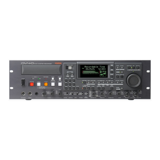
- Page 1 8288 486 000 DVD Master Recorder Model Operation Manual...
-
Page 2: Safety Instructions
CAUTION RISK OF ELECTRIC SHOCK DO NOT OPEN CAUTION: TO REDUCE THE RISK OF ELECTRIC SHOCK, DO NOT REMOVE COVER (OR BACK). NO USER - SERVICEABLE PARTS INSIDE. REFER SERVICING TO QUALIFIED SERVICE PERSONNEL. "WARNING" "TO REDUCE THE RISK OF FIRE OR ELECTRIC SHOCK, DO NOT EXPOSE THIS APPLIANCE TO RAIN OR MOISTURE."... -
Page 3: Table Of Contents
Manual construction ...8 Precautions ...10 Precautions on installation ...10 Precautions on safety ...10 DV40 main features ...11 Chapter-1: Before using the DV40 Turning on the power ...1-2 Setting the internal clock ...1-3 Loading a DVD-RAM disk ...1-4 Formatting a DVD-RAM disk ...1-5 About audio files on a formatted disk ...1-7... - Page 4 Recording time code generated by the internal time code generator ...5-3 Settings of the DV40 ...5-3 Recording external time code ...5-4 Connection to external devices/Setting of the DV40 ...5-4 TC Setup mode details ...5-5 To enter the TC Setup mode ...5-5 Setting the internal TC generator start time ...5-6...
- Page 5 Chapter-7: Locate Function A variety of locate functions ...7-2 Location to the beginning (ABS 0) of an audio file ...7-2 Location to the end (REC END) of the current audio file ...7-2 Location to the last playback start position ...7-3 Location to the last recording start position ...7-3 Location to the last recording end position ...7-3 Location to the point where the recorder located last time ...7-4...
- Page 6 Chapter-12: Using a PS/2 keyboard Controlling the DV40 from a PS/2 keyboard ...12-2 Ineffective keys ...12-2 The common functions between keys on the DV40 and a PS/2 keyboard ...12-3 Accessing setting menus using the [Alt] key ...12-3 Chapter-13: FTP server function FTP server function ...13-2...
- Page 7 Loading setup data ...15-9 TCP/IP settings ...15-10 Showing the IP address ...15-10 Setting the IP address ...15-10 Showing and setting the router IP address ...15-11 Showing and setting the subnet mask ...15-11 Login name/password settings ...15-12 Showing the MAC address ...15-13 Showing the main software version ...15-13 Showing the ethernet software version ...15-13 Chapter-16: Utility mode...
-
Page 8: About This Manual
About this manual This manual is intended to be used as a guide for using the Fostex DV40, a DVD master recorder. It is divided into Chapters. Each Chapter covers instructions for a specific subject or feature of the DV40 which you should know for using the unit, as well as safety instructions, precautions, etc. - Page 9 This chapter describes the FTP (File Transport Protocol) server function of the ETHER card mounted on the DV40. The ETHER card can be used as an FTP server by connecting the ETHER connector on the DV40 rear panel to a personal computer using a LAN cable.
-
Page 10: Precautions
Should water enter the inside of the unit, remove the power cord from AC outlet, and consult your dealer or the nearest Fostex service station. • Do not drop or the unit or give a strong shock to the unit, which may lead to damage of the... -
Page 11: Dv40 Main Features
• Precision analog scrub using a jog dial is possible. • A PS/2 keyboard can be used for file name/label name editing. • You can transfer an audio file on TCP/IP between the DV40 and a personal computer by using the ETHER card as an FTP server. -
Page 13: Chapter-1 Before Using The Dv40
Chapter-1 Before using the DV40 Before using the DV40, you must carry out some preparations. This chap- ter describes how to set the internal clock and how to format a DVD-RAM disk. -
Page 14: Turning On The Power
Turning on the power After connecting the supplied power cord, you can turn on the power of the unit. 1. Press down the [POWER] switch. After showing the start-up display (showing the system clock, followed by "Disk Initialize!"), the unit activates and scans the disk (showing "Scan Disk!"), then shows "No Disk". -
Page 15: Setting The Internal Clock
Setting the internal clock The internal clock is built in the unit, which is adjusted to the Japanese time when shipped. Set the clock to your local time before using according to the following procedure. The internal clock time is used for date information and a tentative name when creating an audio file, as well as necessary data for executing the multiple undo function. -
Page 16: Loading A Dvd-Ram Disk
DV40. <Note> Use a 4.7GB/TYPE 2 DVD-RAM disk with the DV40. The DV40 only can play back data on a 2.6GB disk recorded by other equipment. Please note that the DV40 does not guarantee recording and editing operations with a 2.6GB disk. -
Page 17: Formatting A Dvd-Ram Disk
<About UDF format> The DV40 formats a disk in the UDF “R1.50” format. It can read a disk formatted in the “R1.50” or “R2.0*” format using a personal computer without any difficulty. Note that MAC OS 9.1 supports the “R1.50” format but does not support the “R2.0*”... - Page 18 Tips: How to enter a desired label name Press the [MARGIN RESET/CLR] key repeatedly until the tentative name currently shown is erased. By using the Jog dial (or using the appropriate numeric key), you can enter the desired character at the editing point (flashing point).
-
Page 19: About Audio Files On A Formatted Disk
About audio files on a formatted disk As described earlier, two format modes, Normal and Tape, are available with this unit, and in result, there are two audio file types; "Normal mode" file and "Tape mode" file. In short, a "Normal mode" file is a typical disk recorder file that can be edited comprehensively, while a "Tape mode"... - Page 20 •A disk formatted in the "Tape" format mode Two “Tape mode” audio files (“BWF” or “SDII”) of approximately 2 GB size are created on a disk formatted in the “Tape” format mode. A created file are stored in either of two directories, “bwff” for BWF (Broadcast Wave Format) and “sd2f” (Sound Designer II) files, according to the [AUDIO FILE], [TR MODE] and [SAMPLING FREQ] switch set- tings.
-
Page 21: About Remain Display
About REMAIN display You can check the remaining (recordable) time/space by selecting the appropriate display using the [DISP TIME] key. The unit can show the remaining time and space that can be used for "Normal mode" files, regardless of whether the disk is formatted in the "Normal" or "Tape" mode. •... -
Page 23: Chapter-2 Names And Functions
Chapter-2 Names and Functions This chapter describes names and functions of controls on the front panel, as well as those of connectors on the rear panel. -
Page 24: Front Panel Part 2
Front panel We divide the front panel into three parts and describe names and functions of controls for each section. *Some keys have the secondary function which is available when the SHIFT indicator is lit, while the primary function is available when the SHIFT indicator is unlit. In this manual, we sometimes say "when shifted" and "when unshifted"... - Page 25 In the initial condition, the "DVD" drive is selected. 4. [TAPE MODE] indicator It is lit when a "TAPE mode" audio file is loaded. See "Chapter 1: Before using the DV40" for details about the format mode. 5. [CHASE] ([TC SETUP]) key CHASE This key has primary (unSHIFTed) and secondary (SHIFTed) functions.
- Page 26 6. [LIST PLAY] ([EDIT]) key LIST PLAY This key has primary (unSHIFTed) and secondary (SHIFTed) functions. When unSHIFTed: EDIT Pressing this key allows you to select a list for executing the list play. You can select between “SongLink” and “LTC_Link” lists. After selecting the desired list, pressing the [PLAY] key starts the list play.
- Page 27 c. [PLAY] key Normally, pressing this key starts playback. Pressing this key during recording stores cross fade data to the memory and stops. If any sound data is available on the clipboard, pressing this key while holding down the [STOP] key plays back the sound data. d.
- Page 28 Front panel part 2 OPEN/CLOSE SETUP DATE REMAIN LOCATE MEMORY OFFSET SKIP/CURSOR space INPUT MON MUTE MUTE REC AUDIO RDY NEW FILE INSERT PQRS WXYZ symbol MONO ANALOG +0.1% REMOTE STEREO NORM SDII DIGITAL LOCAL MULTI(4TR) -0.1% PULL CONTROL AUDIO FILE INPUT TR MODE UP/DOWN...
- Page 29 15. [DISP TIME] key DISP Cycles through the time display modes as follows. TIME 16. [DISP LEVEL] key DISP When selecting any time display mode except "REMAIN" using the [DISP TIME] key, LEVEL this key cycles through the display mode as follows. The track level display varies depends on the track mode when recorded.
- Page 30 21. [JOG] key Pressing this key while stopped enters the jog mode, in which you can jog the re- corder as if operating an analog recorder. When the jog mode is active, the indicator is lit. To exit the jog mode, press any of the transport keys. 22.
- Page 31 28. [CUE POINT] ([PREVIEW]) key CUE POINT This key has primary (unSHIFTed) and secondary (SHIFTed) functions. When unSHIFTed: • In the normal display mode, pressing this key enters the cue point edit mode, in which you can edit cue point data. Pressing this key after pressing the [STORE] key stores the holding time to a cue point.
- Page 32 34. [AUDIO EDIT] key AUDIO EDIT pressing this key while stopped enters the menu selection mode for audio editing. In this mode, you can select the editing menu by pressing this key repeatedly or by using the jog dial. See "Chapter 9: Audio file management" and "Chapter 10: Editing track data"...
-
Page 33: Fl Display
40. [AUDIO RDY - NEW FILE] key NEW FILE Pressing this key alternates on and off of the NEW FILE mode. When the mode is active, you can turn on [TC RDY]. In the NEW FILE mode, starting recording automatically creates a new file to be re- corded. -
Page 34: Front Panel Part 3
Front panel part 3 OPEN/CLOSE SETUP DATE REMAIN LOCATE MEMORY SKIP/CURSOR space INPUT MON AUDIO RDY NEW FILE PQRS WXYZ symbol MONO ANALOG +0.1% REMOTE STEREO NORM SDII DIGITAL LOCAL MULTI(4TR) -0.1% PULL CONTROL AUDIO FILE INPUT TR MODE UP/DOWN 43. - Page 35 50. [TC GEN MODE] switch Selects the generator mode for time code recording. The external time code value is recorded as EXT RUN the start time. Runs the internal generator by the free run FREE RUN mode, and records the current internal gen- erator time as the start time.
-
Page 36: Rear Panel
Rear panel ANALOG INPUT BALANCED ANALOG OUTPUT BAL [+4dBu] BAL [+4dBu] UNBAL +4dBu +4dBu -10dBV -10dBV [-10dBV] BAL [+4dBu] BAL [+4dBu] UNBAL +4dBu +4dBu -10dBV -10dBV [-10dBV] 1: GND 2: HOT 3: COLD 1: GND 2: HOT 3: COLD 1. Analog input/output section ANALOG INPUT BALANCED BAL [+4dBu] UNBAL... - Page 37 4. ETHERNET port • Connects to an Ethernet network. ETHERNET • Connector: IEEE802.3, conformed to 10BASE-T/100BASE-T • LED indicators * 10/100: When the connection to a network is established by 10/100 100BASE-TX, this indicator is lit. LINK (It is not lit when the connection TX/RX is established by 10BASE-T.) * LINK: When the unit recognizes the...
- Page 38 B. GPI OUTPUT connector • Connector: DIN-5 pin • The following table shows the pin assignment for event outputs. Pin-1 Outputs an event at Cue point 1. Pin-2 EVENT 1 Outputs an event at Cue point 0. Pin-3 EVENT 0 Outputs an event at Cue point 2.
-
Page 39: Chapter 3 Reformatting/Optimizing A Disk
Chapter 3 Reformatting/optimizing a disk This chapter describes how to reformat a formatted disk and optimize a disk. -
Page 40: Reformatting A Dvd-Ram Disk
• Before reformatting, make sure that the DVD-RAM disk is not write-protected. • If you use an used DVD-RAM disk, we recommended to format the disk by a computer first, then format it by the DV40. 1. While stopped, press the [SHIFT] key to turn on the indicator. - Page 41 The display changes to show "Format Md?" with flashing "Norm". You can select the format mode between "Norm" (Normal) and "Tape" using the jog dial. See "Formatting a DVD-RAM disk" in "Chapter 1 Before using the DV40" for details about the format mode. 6. Select the format mode and press the [ENTER/YES] key.
- Page 42 7. Press the [ENTER/YES] key. • If you reformat the disk in the "Norm" mode, the formatting is completed quickly and "Fmt Completed!" is shown, followed by "No Audio Files!" showing that there is no audio file on the disk. 2018 •...
-
Page 43: Optimizing A Disk
Optimizing a disk By optimizing a used disk, the deleted files are completely erased and you can reserve maxi- mum free block space of the disk. <Note> After optimizing a disk, you cannot restore a deleted file. <Note> Before optimizing, make sure that the DVD-RAM disk is not write-protected. If it is write-protected, you cannot optimize the disk. -
Page 45: Chapter 4 Audio Recording/Playback
Chapter 4 Audio recording/playback This chapter describes the basic audio recording/playback (for both analog and digital), mute recording, slate tone recording, cueing by the jog/shuttle mode, etc. -
Page 46: About The Expression For Audio Files In This Manual
• About the expression for audio files in this manual As described in chapter 1, there are two types of audio file; "Normal mode" audio file and "Tape mode" audio file. "Tape mode" audio file is rather special and can be created only when formatting. The following descrip- tions are mainly associated with a "Normal mode"... -
Page 47: Recording An Analog Source In The New File Mode
The first time you make recording to a disk just after formatted, the maximum recording size of the audio file to be created is 2GB (the maximum recording time depends on the track mode and Fs/bit settings). If the recording size exceeds 2GB during recording, the DV40 automatically stops recording. -
Page 48: Preparation For Recording
Preparation for recording DV D M A S T E R R E C O R D E R DRIVE TAPE MODE POWER RECORD STOP PLAY SOURCE PLAY LOCATE ABS 0 LOCATE REC END TR1,3+2,4 TR3+4 TR1+2 PHONES KEYBOARD MOUSE 1. -
Page 49: Recording
Recording 1. Press the [RECORD] key. "New File!" appears for a short time on the display and the unit starts recording on the newly created file with the file format set in the procedure described in the previous "Preparation for recording". A tentative title of the newly created audio file is automatically created and registered. -
Page 50: Playback Of Recorded Audio
Playback of recorded audio To check the recorded audio file after recording, follow the procedure below. 1. While holding down the [STOP] key, press the [REWIND] key. The unit immediately locates to the beginning of the audio file. 2. Press the [PLAY] key to start playback from the beginning of the audio file. 3. -
Page 51: Recording An Analog Source In The Insert Mode
Recording an analog source in the INSERT mode In the INSERT mode, recording is made to an existing audio file. You can overwrite the file from the beginning or in the middle of the file, as well as make recording following the end of the file. In the following description, as with the earlier description in “Recording an analog source in the NEW FILE mode”, we assume that we are going to record an external stereo analog audio source from the [ANALOG INPUT - TR1] and [ANALOG INPUT - 2] connectors to a DVD-RAM disk loaded in the tray. -
Page 52: Multiple-Undo Function
Multiple-undo function To undo recording, use the multiple-undo function. Tips: The history of takes starts by the date/time when the file was created, followed by the ending date/time of each recording take, as illustrated below. By selecting the desired history event and performing the undo function, you can recall the desired take. -
Page 53: Selecting A Desired File On A Disk
Selecting a desired file on a disk When there is more than one audio file (regardless of "BWF" or "SDII") on a disk, you can select a desired file using the file select function, or using the [SKIP/CURSOR] [I<<]/[>>I] keys if the “skip mode” menu is set to “File”. -
Page 54: Recording To A "Tape Mode" Audio File In The Insert Mode
Recording to a "Tape mode" audio file in the INSERT mode You can record to a "Tape mode" audio file only in the INSERT mode. If an accident may happens, such as a sudden power failure or shutdown of the unit, recorded data on a "Tape mode"... -
Page 55: Creating A "Normal Mode" Audio File On A Disk Formatted In The Tape Mode
Creating a "Normal mode" audio file on a disk formatted in the Tape mode Two "Tape mode" audio files of approximately 2.0GB size are created on a disk formatted in the Tape mode, spending 4GB disk space. Therefore, in the remaining 0.7GB space, you can create "Normal mode" audio files. -
Page 56: Recording A Digital Source In The New File Mode
The first time you make recording to a disk just after formatted, the maximum recording size of the audio file to be created is 2GB (the maximum recording time depends on the track mode and Fs/bit settings). If the recording size exceeds 2GB during recording, the DV40 automatically stops recording. -
Page 57: Preparation For Recording
Preparation for recording DV D M A S T E R R E C O R D E R DRIVE TAPE MODE POWER TC SETUP RECORD STOP PLAY SOURCE PLAY LOCATE ABS 0 LOCATE REC END TR1,3+2,4 TR3+4 TR1+2 PHONES MOUSE KEYBOARD 1. -
Page 58: Recording A Digital Source In The Insert Mode
Recording a digital source in the INSERT mode In the following description, we assume to perform recording from the end point of the cur- rent audio file, as in the description of the “Recording an analog source in the INSERT mode” described earlier. -
Page 59: Mute Recording
MUTE recording You can make mute recording while maintaining the continuity of the ABS time (or LTC), or insert a mute space at the beginning of an audio file or between songs. • Creating a mute space during recording You can create a mute space during audio recording (analog or digital) in both the NEW FILE and INSERT mode. -
Page 60: Slate Tone Function
Slate tone function During playback or while stopped, you can feed the 1-kHz slate tone from all the outputs, as well as record the slate tone for a specified duration at the beginning of an audio file or between songs. •... -
Page 61: Cueing By The Jog Function
Cueing by the jog function You can cue audio sound using the jog function as if you operate an analog tape recorder. 1. While stopped, press the [JOG] key (the JOG indicator lights up). The jog mode is active. indicator above the jog dial lights up, showing that the recorder stills. 2. -
Page 63: Chapter 5 Time Code Recording
Chapter 5 Time code recording This chapter describes how to record time code generated by the internal time code generator or external time code. -
Page 64: Selecting The Recording Mode
• External time code received from the [TIME CODE INPUT] connector. <Note> Actually, the DV40 records only the starting time of time code in the dedicated area and does not stripe it throughout a track. Therefore, recording time code does not consume the recording space of a disk. -
Page 65: Recording Time Code Generated By The Internal Time Code Generator
4. After pressing the [SHIFT] key to make the SHIFT mode active, press the [CHASE/(TC SETUP)] key to enter the TC SETUP mode, then preset the internal time code generator time if necessary. See page 5-6 for details about how to preset the internal time code generator time. Settings of the DV40 OPEN/CLOSE SKIP/CURSOR... -
Page 66: Recording External Time Code
1. Connect the [ANALOG IN] (or [DIGITAL IN]) connectors to the audio outputs of a VCR. 2. Connect the [TIME CODE IN] connector to the time code output of a VCR. 3. If the video reference is available, connect it to the video inputs of both a VCR and the DV40. ANALOG INPUT BALANCED... -
Page 67: Tc Setup Mode Details
TC Setup mode details The TC Setup mode allows you to set the following which are necessary for recording/play- back of time code or synchronizing the unit to external time code. 1. Editing time code generated by the internal TC generator 2. -
Page 68: Setting The Internal Tc Generator Start Time
The internal generator starts from the entered time when the [TC GEN MODE] switch is set to “FREE RUN”. The DV40 can start recording from the entered time when the [TC GEN MODE] switch is set to “REC RUN”. • Force-jamming to external time code You can force-jam the internal generator time code to external time code. -
Page 69: Selecting Output Time Code
• Selecting output time code When setting the [TC GEN MODE] switch to "FREE RUN" or "24H RUN", you can output time code generated by the internal TC generator or recorded on the disk. <Notes> • The time code output selection is not effective when setting the [TC GEN MODE] switch to "REC RUN"... -
Page 70: Trimming The Chase Offset
• Trimming the chase offset You can trim the chase offset set by the procedure described above in "Editing the chase offset". 1. Use the jog dial (or [SKIP/CURSOR] [|<<] / [>>|] keys) to select "Trim?". The current chase offset is shown. 2. -
Page 71: Catch Offset
• Catch offset you can capture the current LTC and store it as the chase offset by the "Catch Offset" function. This function is available both during playback and while stopped. 1. Use the jog dial (or [SKIP/CURSOR] [|<<] / [>>|] keys) to select "Catch Offset?". The current LTC is shown. - Page 72 This menu allows to select the TIME CODE UBIT information attached to the time code output from the DV40. The date information on “MDYf” and “DMYf” is taken out from the internal clock on DV40 and is based on the time when the file is created. “SRNo” information is derived from the 3-digit REEL NUMBER attached to the VOLUME LABEL set in the “Edit Volume Lbl?”...
- Page 73 SCENE No. derived from “Set SCENE & REEL?” Utility menu + File No. RRR: 3-digit REEL No. derived from “Edit Volume Lbl?” Utility menu or “Set SCENE & REEL?” Utility menu. <Example-1> VOLUME LABEL: DV40-002 SCENE/REEL No.: 00000 / 002 File No.: TC UBIT Information: 00001002 •...
-
Page 75: Chapter 6 Storing Time Data
Chapter 6 Storing time data This chapter explains how to store time data to location memories for the track editing or locate functions. -
Page 76: Location Memory Keys
Location memory keys 6 location memory keys are used to store location data for the track editing (for copy, paste, insert, erase, etc.) and locate functions. The location memory keys include four "edit point keys" and two "locate point keys". The table below shows their names and usage of the corresponding location memories. -
Page 77: Storing A Time To An Edit Point Memory
Storing a time to an edit point memory The following describes how to store a time to an edit point memory required for track edit- ing. There are two methods for enter a time; "on the fly" and "numerical entry". <Notes>... -
Page 78: Storing A Time To An Edit Point Using The Numeric Keys
• Storing a time to an edit point using the numeric keys You can recall and edit an edit point time and store the edited time. 1. While stopped, press a desired edit point key. The display shows the appropriate edit point time. You can now edit the time. - Page 79 Storing a time to a locate point memory (CUE/MEMORY) Using the [CUE POINT] or [MEMORY] key, you can store a desired point time to a locate point memory, and use it to locate there later. You can also give desired names to them or clear the data.
-
Page 80: Storing A Time To A Locate Point Memory Cue Or Memory Point Memory) "On The Fly"
• Storing a time to a locate point memory (CUE or MEMORY point memory) "on the fly" During playback, you can store a desired time to a locate point memory (CUE or MEMORY point memory) "on the fly". 1. Press the [PLAY] key to start playback. 2. -
Page 81: Storing A Time To A Locate Point Using The Numeric Keys
• Storing a time to a locate point using the numeric keys You can recall and edit a locate point (CUE or MEMORY point) time and store the edited time. 1. While stopped, press a desired locate point key ([CUE POINT] or [MEMORY] key). The display shows the locate bank and memory number (e.g. -
Page 82: Editing A Name Of Cue Or Memory Point
Editing a name of CUE or MEMORY point When storing time data to a locate point memory, the tentative name, such as "Cue 01" and "Mem 05", is given to the memory. You can edit the name later. <Note> You cannot edit/change the names for MEMORY 01 (Last Play), 02 (Last Record In) and 03 (Last Record Out). -
Page 83: Clearing A Cue Or Memory Point Memory
Clearing a CUE or MEMORY point memory You can clear an unnecessary locate point memory (CUE or MEMORY). 1. While stopped, press a desired locate point key ([CUE POINT] or [MEMORY] key). The display shows the locate bank and memory number (e.g. "Cue 03"), and a locate point time with flashing memory number. -
Page 85: Chapter 7 Locate Functions
Chapter 7 Locate functions This chapter describes various locate functions including direct location to the beginning or end of an audio file, location to a locate or edit point, and skip location between locate points or audio files. -
Page 86: A Variety Of Locate Functions
A variety of locate functions The following locate functions are available. Location to the beginning (ABS0) of the current audio file Location to the end (REC END) of the current audio file Location to the last playback start position Location to the last recording start position Location to the last recording end position Location to the point where the recorder located last time Location to an audio edit point... -
Page 87: Location To The Last Playback Start Position
• Location to the last playback start position You can locate to the point between ABS 0 and REC END where playback started last time. 1. When the recorder is stopped, press the [MEMORY] key. The display shows the screen for recalling a locate point memory. The first time you press the [MEMORY] key after turning on the power, "Last Play"... -
Page 88: Location To The Point Where The Recorder Located Last Time
• Location to the point where the recorder located last time You can locate to the point between ABS 0 and REC END where the recorder located last time. 1. When the recorder is stopped, press only the [LOCATE] key. The recorder locates to the point where the recorder located last time. -
Page 89: Location To The Next Or Previous Cue/Memory Point Using The Skip Mode
• Location to a MEMORY point By specifying a desired MEMORY point memory (among 04 through 99), you can locate to the point. 1. When the recorder is stopped, press the [MEMORY] key. The display shows a MEMORY point time with the flashing point number. 2. -
Page 91: Chapter 8 Preview Function
Chapter 8 Preview function This chapter describes the fade-in/fade-out preview function at the edit or lo- cate points assigned to the location memory keys. -
Page 92: Preview At An Edit Point
Preview function The preview (point rehearsal) function allows you to preview (monitor) an edit or locate point assigned to the [SOURCE IN], [SOURCE OUT], [DEST IN], [DEST OUT], [CUE POINT] or [MEMORY] key. When previewing an edit IN or locate point, you can monitor audio faded in from the point (fade-in preview). -
Page 93: Preview At A Locate Point
• Preview at a locate point You can preview audio faded in from a desired locate point (selected from among CUE points 01 through 99 and MEMORY point 01 through 99). The following procedure is assumed that the locate point you want to preview is stored. <Note>... -
Page 94: Trimming While Previewing Audio
• Trimming while previewing audio You can trim time data using the jog dial while previewing audio, allowing the fine adjustment of an edit or locate point. <Note> • When trimming time data while previewing, the trimmed data is reflected from the next pre view. -
Page 95: Chapter 9 Audio File Management
Chapter 9 Audio file management This chapter describes the management of audio files. -
Page 96: Creating A New Audio File
Creating a new audio file Regardless of whether a disk is formatted in the Normal or Tape mode, you can newly create only a "Normal mode" audio file by using the file select function. <Note> To record to an audio file created by the file select function, use the INSERT mode. •... -
Page 97: Creating A New File On A Disk Just After Formatted In The Tape Mode
• Creating a new file on a disk just after formatted in the Tape mode You can create more than one "Normal mode" audio file (of the "BWF" or "SDII" format) on a disk formatted in the Tape mode. In the following procedure, we assume that a disk just after formatted in the Tape mode is loaded and a "Tape mode"... -
Page 98: Selecting An Audio File
Selecting an audio file You can select an audio file by using the file select or skip function. Tips: By using the "File Sort?" menu in the Setup mode, you can sort audio files by name or date, allowing file selection easier. -
Page 99: Editing An Audio File Name
Editing an audio file name You can edit a name of the current audio file. Before carrying out the following, select an audio file whose name you want to edit as the current file. 1. While stopped, press the [SHIFT] key to turn on the indicator. 2. -
Page 100: Deleting An Audio File
Deleting an audio file You can delete an unnecessary audio file. Before carrying out the following, select an audio file you want to delete as the current file. 1. While stopped, press the [SHIFT] key to turn on the indicator. 2. -
Page 101: Restoring A Deleted Audio File
Restoring a deleted audio file You can restore a deleted audio file. <Note> The restored audio file returns to the position where it was before the delete operation. However, the editing data carried out before deleting the file does not remain, therefore, you cannot carry out the undo operation with the restored file. -
Page 102: Duplicating An Audio File
Duplicating an audio file You can duplicate the currently selected audio file. By making a duplication of the current audio file before executing the undo operation, you do not lose the current file. Tips: File number of the duplication file The duplication file is numbered one more than the number of existing files of the same format ("BWF"... -
Page 103: Chapter 10 Editing Track Data
Chapter 10 Editing track data This chapter describes how to edit track data using the paste, insert, cut and erase functions. -
Page 104: Pasting Track Data
Pasting track data You can copy track data between the "SOURCE IN" and "SOURCE OUT" points to the clipboard and paste it from the "DEST IN" point on the same or a different track. Paste to the same track Paste to the other track <Note>... - Page 105 Tips: SOURCE-PLAY You can monitor the track data copied to the clipboard us- ing the SOURCE-PLAY function before carrying out the paste operation. Pressing the [PLAY] key while holding down the [STOP] key caries out the SOURCE-PLAY function, which plays back the track data on the clipboard and stops.
-
Page 106: Inserting Track Data
Inserting track data You can copy track data between the "SOURCE IN" and "SOURCE OUT" points to the clipboard and insert it to the "DEST IN" point on the same or a different track. Tips: The REC END point of the file to which track data is inserted to moves backward. <Note>... - Page 107 Tips: You can monitor the track data copied to the clipboard using the SOURCE-PLAY function before carry- ing out the insert operation. See "Tips: SOURCE-PLAY" on page 10-3. 5. Use the jog dial to select "Insert Clip?" and press the [ENTER/YES] key. "Sel.Insert TRK?"...
-
Page 108: Erasing Track Data
Erasing track data You can erase track data between the "SOURCE IN" and "SOURCE OUT" points. Tips: The erase operation erases only sound data, therefore, by erasing track data of a specified area between "ABS 0" and "REC END", the REC END point does not change and the time code is not affected. 1. - Page 109 5. Press the [ENTER/YES] key. The unit starts erasing track data between the "SOURCE IN" and "SOURCE OUT" points of the specified track(s). The display shows the required time together with the achieved percentage for erase. The time is counted down while the percentage is counted up as the erase operation is in progress. Also, the status is graphically shown by the track 1 level indicators which gradually light up from left to right.
-
Page 110: Cutting Track Data
Cutting track data You can cut track data between the "SOURCE IN" and "SOURCE OUT" points. <Note> You cannot cut operation with a “ Tape mode ” audio file. Tips: If you cut data for all tracks, the REC END point of the file moves forward. If you cut data for some of tracks, “0”... - Page 111 4. Press the appropriate edit point key(s) ([SOURCE IN], [SOURCE OUT], [DEST IN] or [DEST OUT] keys) to select the track(s) to be cut, and press the [ENTER/YES] key. * These edit point keys are used to select tracks 1 through 4 (TR 1 through TR 4), as labeled below the keys. Depending on the track mode of the audio file, the selectable tracks are restricted.
-
Page 113: Chapter 11 List Play Function
Chapter 11 LIST PLAY function This chapter describes the list play function, by which you can play back more than one recorded audio file continuously. - Page 114 <<Silent Area>> is also displayed in the deleted File No. 005 LTC section (01h02m30s00f ~ 01h03m00s00f). In the SongLink mode, DV40 just simply links the File No. 001 ~ 004 and 006 regardless of LTC START address setting on the File No. 002 ~ 004 and 006. Then, it reproduces each file continuously.
-
Page 115: Turning On List Play Mode
After pressing the [ENTER/YES] key, “<<Wait!>>” message starts flashing for a short while indicating that DV40 is creating a linked file list on the DV40 FL display. Then, the [LIST PLAY/(EDIT)] key will be lit solid. This indicates that the selected LIST PLAY mode is turned ON. -
Page 116: Reprogramming Play List
DVD-RAM disk. After optimizing, they can be no longer restored. <Note> A deleted file before optimizing on DV40 is categorized as a “ hidden file ”. It can be seen as a translucent file on a personal computer. (If the folder option “A hidden files are not displayed.” on the computer is selected, change the folder option setting to allow to display hidden files.) -
Page 117: Chapter 12 Using A Ps/2 Keyboard
Chapter 12 Using a PS/2 keyboard This chapter describes how to control the DV40 using a PS/2 keyboard con- nected to the [KEYBOARD] terminal. -
Page 118: Controlling The Dv40 From A Ps/2 Keyboard
Controlling the DV40 from a PS/2 keyboard By connecting a PS/2 keyboard to the [KEYBOARD] terminal on the front panel of the DV40, you can easily carry out various operation such as file name or volume label editing. DV D M A S T E R R E C O R D E R... -
Page 119: The Common Functions Between Keys On The Dv40 And A Ps/2 Keyboard
The common functions between keys on the DV40 and a PS/2 keyboard The PS/2 keyboard keys shown below act the same function as the associated keys or jog dial on the DV40 front panel. PS/2 keyboard Pressing the Pressing the... -
Page 121: Chapter-13: Ftp Server Function
Chapter 13 FTP Server Function This chapter describes the FTP server function using the ETHER card mounted on the DV40. -
Page 122: Ftp Server Function
To interrupt the data transfer, send the "abort" command from the FTP client or alter the [CONTROL] switch on the DV40 front panel to "LOCAL" . • When the DV40 is in the initial condition, you can log in even if you do not enter the login name and password. -
Page 123: Ftp Command Compliance
FTP Command Compliance The following FTP commands can be used when DV40 works as a FTP server. USER Identifying user name. PASS Identifying password. QUIT Terminating FTP connection. TCP connection for Control is also cut off. PORT When transferring data, relay the connection state open port number for data transferring at client side to server. -
Page 124: Checking Tcp/Ip Menus
Checking TCP/IP Menus There are several menus in the TCP/IP settings on DV40. First, press the [SETUP] key and then rotate the jog dial. While the menu “TCP/IP Setup?” is displayed, press the [ENTER/YES] key. SETUP By rotating the Jog dial, the menu changes as shown below. -
Page 125: Changing The Tcp/Ip Setting
DV40 FL display. SETUP Now you can see that the current IP Address setting on DV40 is [192. 168. 1. 64]. 2. Press the [ENTER/YES] key. If the [ENTER/YES] key is pressed, the section “192” starts flashing. -
Page 126: Sub Net
Pressing the [ENTER/YES] key defines the change on the Gateway. • Sub net The Sub net mask value in the network DV40 exists should be set. In the case the Sub net mask is not used, you do not have to set this value. -
Page 127: Mac Address
• MAC Address The MAC (Machine Access Control) address is the 48-bit machine-specific fixed address, so that DV40 used in a network environment can be identified. It can be checked but not changed. 1. Rotate the jog dial to select “Mac Addr. [00. 06.”. -
Page 129: Chapter 14 Importing An Audio File To A Computer
Chapter 14 Importing an audio file to a computer This chapter describes how to import an audio file created by the DV40 to a computer. -
Page 130: Importing An Audio File To The Digidesign Pro Tools
3. Select and double-click on "DV40-DVD" on the desktop. The disc volume name in the following example shows the default tentative name. If you edited the volume name during formatting of the DVD-RAM disc by the DV40, the edited name is shown. - Page 131 4. Select the desired directory ("bwff" or "sd2f") on the disc. 5. Double-click on a desired audio file in the selected directory. The selected audio file is shown in the "Region in current file" box. 6. Click on "Convert->", followed by "Done". The window for selecting a destination folder for the saved file appears.
- Page 132 The saved file is shown in the Audio region list. The saved file is shown. 8. Click on "Spot" to make it active, and drag & down the Audio region list to the track area. The Spot Dialog window appears. 14-4...
- Page 133 9. Click on in the Spot Dialog window, followed by "OK". Clicking on sets the currently displayed time of "Original Time Stamp" to the "Start" time. Then clicking on "OK" imports audio data from the "Start" time position. The currently displayed time of "Original Time Stamp"...
-
Page 135: Chapter-15: Setup Mode
Chapter 15 Setup mode In the Setup mode, you can set preferences, etc. of the unit as below. 1. Internal clock time adjustment (see chapter 1 for details.) 2. Display contrast setting 3. Reference level setting 4. Digital input track selection 5. -
Page 136: How To Access And Set A Setup Menu
How to access and set a Setup menu <Note> You can access the Setup menu while the unit is stopped and is not in the Utility or TC Setup mode. Note that the operation procedure shown below is not applied to the " RS422 Setup " and " TCP/IP Setup " menus. -
Page 137: Display Contrast Setting
Display contrast setting You can control the display contrast via the "Con- trast?" menu. This setting is global and is not dependent on files. The setting is maintained after you turn off the power. You can save or load the setting. SETUP Flashing SETUP... -
Page 138: Skipped Item Selection For The Skip Mode
Skipped item selection for the skip mode You can select the item to be skipped in the skip mode. This setting is dependent on files and is maintained after you turn off the power. You can save or load the setting. SETUP Flashing SETUP... -
Page 139: Setting Rs-422
To make setting, select the desired setting items and press the [ENTER/YES] key, then select the desired option using the jog dial and press the [ENTER/YES] key. 1. Device code You can emulate the device code of the DV40 to the other device. SETUP SETUP Flashing “DV40”... -
Page 140: Peak Hold Time Setting
Peak hold time setting You can set the peak hold time of the level meters on the display. This setting is global and is not dependent on files. The setting is maintained after you turn off the power. You can save or load the setting. SETUP Flashing SETUP... -
Page 141: File Name Mode Setting
"DefaultFileName?" menu and are effective only when setting "F.Name MD?" to "TAKE". If you create a new audio file, the DV40 gives a file name starting by the specified file name, followed by the take number and ended by the file exten- sion. -
Page 142: Save/Load Of Setup Data
[STOP] key goes back to the normal display. By the above procedures, the default file name is set to “DV40-005”. If the “TAKE” File Name Mode is selected, every time a file is newly created, it will be named as “DV40-5”, “DV40-6”, ...”DV40-9”, “DV40-10”, “DV40-... -
Page 143: Loading Setup Data
4. After entering a desired name, press the [ENTER/ YES] key. "Sure?" flashes on the display. SETUP Flashing 5. Press the [ENTER/YES] key again. The unit immediately saves the name and shows "Completed!", followed by "Save Use Setup?". SETUP SETUP 6. -
Page 144: Tcp/Ip Settings
TCP/IP settings The "TCP/IP Setup?" menu allows you to set param- eters for transferring audio file data between the DV40 and your personal computer via the TCP/IP. <Note> When changing the TCP/IP setting, turn the DV40 power off then on. Otherwise, the new setting is not effective. -
Page 145: Showing And Setting The Router Ip Address
• Showing and setting the router IP address You can check or/and assign the IP address for a gateway server in the network. If a gateway server is not used, this setting is not necessary. Showing the router IP address 1. -
Page 146: Login Name/Password Settings
Administrator or User 01 through 15. Showing the login name/password 1. Select "Login Name Admin?" and press the [ENTER/YES] key. The current login name for the administrator is shown (the default is "DV40"). The leftmost character of the name is flashing. SETUP SETUP Flashing 2. -
Page 147: Showing The Mac Address
• Showing the MAC address 1. Select "MAC Addr.?" and press the [SKIP/CURSOR >>I] key repeatedly. The assigned MAC address shown on the display scrolls left. Pressing the [SKIP/CURSOR |<<] key scrolls right. SETUP SETUP SETUP 2. To exit the Setup mode, press the [EXIT/NO] key or [STOP] key. -
Page 149: Chapter-16: Utility Mode
This chapter describes details about the Utility mode. This mode deals with preference menus, as well as execution menus for disc format- ting, optimizing, etc. <Note> There are 11 menus in the Utility mode, however, this chapter describes details about only "Menu 1" through "Menu 6". See the appropriate sections indicated in parentheses for details about menu items 7 through 11. -
Page 150: How To Select A Utility Menu
How to select a Utility menu <Note> You can enter the Utility mode while the unit is stopped and is not in the Setup or TC Setup mode. 1. While the unit is stopped, press the [SHIFT] key to enter the shift mode (the SHIFT indicator lights up). 2. -
Page 151: Renumbering Cue Points
Renumbering CUE points This menu allows renumbering CUE points. When CUE points are renumbered, CUE points are numbered in order of time. This function is useful after deleting a CUE point or the current CUE points are not stored in order of time. -
Page 152: Selecting On Or Off Of The Resume Function
The “Volume Label” is name which is used to iden- tify a disk. It is normally named when formatting a disk. As mentioned in the DV40 owner’s manual page 1-5, the default name of Volume Label to be attached to the DVD-RAM disk is “DV40-DVD”. -
Page 153: Setting User Bit Data
When formatting the DVD-RAM disk, renaming the VOLUME LABEL with 3-dogit number (e.g. DV40- 005) from the default name (DV40-DVD) is pos- sible, so that the 3-digit number can be recognized as a REEL NUMBER which allows to output as a TC UBIT information. -
Page 155: Chapter 17 Specifications
Chapter 17 Specifications... -
Page 156: Specifications
Specifications <Inputs/Outputs> *0 dBu - 0.775 Vrms, 0 dBV = 1 Vrms. Reference level Nominal input level ANALOG INPUTs (TR 1 through TR 4) • Connector • Input impedance • Nominal input level • Maximum input level ANALOG OUTPUTs (TR 1 through TR 4) •... - Page 157 Pin 5: << The "low" pulse activates the function equivalent to the [|<<] key. * The minimum effective input pulse width is 15 milliseconds (except Pin 2 [PLAY] whose minimum pulse width is 5 milliseconds). GPI OUT Pin 1: Pin 2: EVENT 1 Outputs the event of CUE POINT 1 Pin 3:...
- Page 158 * Specifications and appearance are subject to change without notice for product improvement. D-sub 9-pin (9P-REMOTE) D-sub 15-pin (15P-REMOTE) RS-232C, conformed to the Sony 9-pin (P2) protocol (The DV40 is a controlled device.) D-sub 15P DATA IN Frame Ground Transmit A...
- Page 159 Memo 17-5...
-
Page 160: Declaration Of Ec Directive
In the electrical fast transient/burst requirements, surge, conducted disturbances by radio-frequency fields, power frequency magnetic field, radiate electromagnetic field requirements and static electricity discharging environment, this could be affected by generation of noise in some cases. FOSTEX DISTRIBUTORS LIST IN EUROPE * Including non-EU countries (as of January, 2002) <AUSTRIA>... - Page 162 FOSTEX CORPORATION 3-2-35 Musashino, Akishima-shi, Tokyo, Japan 196 -0021 FOSTEX AMERICA 15431, Blackburn Ave., Norwalk, CA 90650, U. S. A. PRINTED IN JAPAN APRIL 2002 8288 486 000 FX ©...
Need help?
Do you have a question about the DV40 and is the answer not in the manual?
Questions and answers