
Subscribe to Our Youtube Channel
Related Manuals for Beckhoff AMI8100


Summary of Contents for Beckhoff AMI8100
- Page 1 Operating instructions | EN AMI8100 Compact integrated Servo Drives 1/31/2022 | Version 1.0...
-
Page 3: Table Of Contents
Version numbers............................... 7 Scope of the documentation .......................... 7 Staff qualification............................... 8 Safety and instruction ............................. 10 Explanation of symbols ........................... 10 Beckhoff Services ............................ 12 For your safety.............................. 13 Safety pictograms ............................ 13 General safety instructions .......................... 14 Product overview............................... 16 Name plate.............................. - Page 4 Gear unit ................................. 54 Decommissioning.............................. 55 Disassembly.............................. 55 Disposal ................................ 56 Guidelines and Standards .......................... 57 Standards................................ 57 Guidelines ............................... 57 Test centers .............................. 57 EU conformity .............................. 58 CCC conformity............................... 58 UL conformity.............................. 58 Index ................................... 59 ─── AMI8100 Version: 1.0...
-
Page 5: Documentation Notes
Documentation notes Disclaimer Beckhoff products are subject to continuous further development. We reserve the right to revise the operating instructions at any time and without prior announcement. No claims for the modification of products that have already been supplied may be made on the basis of the data, diagrams and descriptions in these operating instruc- tions. - Page 6 • Use of untrained personnel • Use of unauthorized spare parts Copyright © Beckhoff Automation GmbH & Co. KG, Germany 1.1.4 The copying, distribution and utilization of this document as well as the communication of its contents to others without express autho- rization is prohibited.
-
Page 7: Version Numbers
Product features Only the product properties specified in the current operating in- structions are valid. Further information given on the product pages of the Beckhoff homepage, in emails or in other publications is not authoritative. Scope of the documen- Apart from these operating instructions, the following documents are... -
Page 8: Staff Qualification
Trained specialists have received specific technical training and have specific technical knowledge and experience. Trained special- ists can: • apply relevant standards and directives • assess tasks that they have been assigned • recognize possible hazards • prepare and set up workplaces ─── AMI8100 Version: 1.0... - Page 9 They are familiar with relevant standards and directives. Quali- fied electricians can: • independently recognize, avoid and eliminate sources of danger • implement specifications from the accident prevention regula- tions • assess the work environment • independently optimize and carry out their work Version: 1.0 AMI8100 ───...
-
Page 10: Safety And Instruction
1.6.1 DANGER Failure to observe will result in serious or fatal injuries. WARNING Failure to observe may result in serious or fatal injuries. CAUTION Failure to observe may result in minor or moderate injuries. ─── AMI8100 Version: 1.0... - Page 11 In the case of documentation on a monitor screen, use the zoom function to enlarge the QR code and reduce the distance. Version: 1.0 AMI8100 ───...
-
Page 12: Beckhoff Services
Beckhoff and the worldwide partner companies offer comprehensive support and service. Support The Beckhoff Support offers technical advice on the use of individ- ual Beckhoff products and system planning. The employees support 1.7.1 you in the programming and commissioning of complex automation systems. -
Page 13: For Your Safety
Safety pictograms Beckhoff products feature safety pictograms, either on stickers or printed, which vary depending on the product. They serve to protect people and to prevent damage to the products. Safety pictograms must not be removed and must be legible for the user. -
Page 14: General Safety Instructions
Observe tightening torques Mount and repeatedly check connections and components, comply- ing with the prescribed tightening torques. Use the original packaging only When shipping, transporting, storing and packing, use the original packaging or conductive materials. ─── AMI8100 Version: 1.0... - Page 15 Secure the machine or plant against being in- advertently started up. Observe the chapter: "Decommissioning". No direct skin contact with solvents or lubricants In case of improper use, the solvents or lubricants used can lead to skin irritations. Therefore, avoid direct skin contact. Version: 1.0 AMI8100 ───...
-
Page 16: Product Overview
Product overview Item number Explanation Housing Feather key [+] Sensor connection M8; 3-pin Power connection M12; 5-pin EtherCAT connection M8; 4-pin Shaft Radial shaft-sealing ring [+] ─── AMI8100 Version: 1.0... -
Page 17: Name Plate
Max. supply voltage 48 VDC Max. supply voltage 24 VDC Protection class Hardware code UL approval for USA / CAN Bus system EAC approval / UKCA approval Data-Matrix Code; BIC = Beckhoff Identification Code CE conformity Note on proper disposal Version: 1.0 AMI8100 ───... -
Page 18: Type Key
2 = shaft with radial shaft-sealing ring IP 65 and smooth shaft 3 = shaft with radial shaft-sealing ring IP 65, groove and feather key Winding type Fieldbus 1 = EtherCAT Holding brake 0 = without holding brake 1 = with 24 V holding brake ─── AMI8100 Version: 1.0... -
Page 19: Product Characteristics
A thermal contact LPTC-600 is installed to monitor and measure the winding temperature and to protect the servo drive against overheat- ing. This can be read out by the user. Temperature warning and switch-off: • Warning temperature at 120 °C • Switch-off temperature at 140 °C Version: 1.0 AMI8100 ───... - Page 20 3000 rpm with a maximum of three times the intrinsic inertia of the motor. These maximum values may vary due to increased load inertia. The function of the holding brake can be checked with a torque wrench or with TwinCAT Scope. ─── AMI8100 Version: 1.0...
-
Page 21: Ordering Options
A holding brake blocks the rotor in the de-energized state. The hold- ing brake increases the motor length and the rotor moment of iner- tia. The holding brake cannot be retrofitted and is mounted on the B bearing side of the servo drive. Version: 1.0 AMI8100 ───... - Page 22 3.4.3 technology For the operation of the servo drives with integrated safety technol- ogy original Beckhoff connection cables are mandatory. This is part of the safety certification. Observe the TwinSAFE documentation Before putting the servo drives with integrated safety technology into operation, read the documentation: •...
-
Page 23: Intended Use
Any type of use that exceeds the permissible values from the techni- cal data is regarded as inappropriate and is thus prohibited. 3.5.1 The compact integrated servo drives of the AMI8100 series are not suitable for use in the following areas: • ATEX zones without suitable housing •... -
Page 24: Technical Data
Definitions Characteristic torque and speed curves Detailed information on characteristic curves can be found under: Beckhoff motor curves All data, with the exception of the voltage constant, are based on 40 °C ambient temperature and 100 K overtemperature of the wind- ing. The data can have a tolerance of +/-10 %. - Page 25 Winding inductance L [mH] Specification of the servo drive inductance. It is the average value for one revolution, with two energized phases, at 1 kHz. Saturation of the servo drive must be taken into account. Version: 1.0 AMI8100 ───...
-
Page 26: Data For Operation And Environment
Technical data Data for operation and Beckhoff products are designed for operation under certain environ- mental conditions, which vary according to the product. The follow- environment ing specifications must be observed for operation and environment in order to achieve the optimum service life of the products. -
Page 27: Ami812X
[Nm] 0.45 0.78 0.75 0.97 Nominal output P Nominal current In [A] Reference flange aluminum 230 mm x 130 mm x 10 mm Installation of a shaft sealing ring leads to a reduction of the nominal values. Version: 1.0 AMI8100 ───... - Page 28 Anthracite gray; RAL 7016 Optional holding brake [+] AMI812x Holding torque at 120 °C M [Nm] Supply voltage U 24; +6% to -10% Electrical power P Current at 120 °C I Release delay time t [ms] Application delay time t [ms] ─── AMI8100 Version: 1.0...
- Page 29 Technical data Dimensional drawing • All figures in millimeters 4.3.1 Motor Z - brake AMI8121 189.5 AMI8122 211.5 AMI8123 233.5 Feather key [+] • Center bore according to DIN 332-D Version: 1.0 AMI8100 ───...
- Page 30 Technical data Force diagram Beckhoff load/force calculator 4.3.2 The software represents axial and radial forces on the servo drive shaft. The following example shows an AMI8122 without a holding brake. • Download load/force calculator ─── AMI8100 Version: 1.0...
-
Page 31: Scope Of Supply
+65°C These are the permitted maximum and minimum temperatures at which the device may be stored and transported. -25°C This is the correct position for the packaging. Protect the packaging against wetness. The contents are fragile. Version: 1.0 AMI8100 ───... -
Page 32: Transport And Storage
• Use of the vendor's original packaging The table shows the maximum stacking height at which you may store and transport the servo drives on a pallet in the original pack- aging: Motor type Stacking height [pieces] AMI812x ─── AMI8100 Version: 1.0... -
Page 33: Transport
High mechanical stresses will damage the distributed servo drive system and individual components. AMI81xx Transport of the compact integrated servo drives of the AMI81xx se- ries without auxiliary means. 6.2.1 Version: 1.0 AMI8100 ───... -
Page 34: Long-Term Storage
"Transport and storage", [Page 32]. The servo drives are protected against chemical and aggressive substances through the classes 1C2, chemical substances and 1B2, biological conditions. Ensure the storage space is vibration-free. ─── AMI8100 Version: 1.0... -
Page 35: Technical Description
It is not possible to change the feedback system retro- spectively. The table below provides information about system accuracies and resolutions of the servo drive feedback systems: Feedback Resolution System accuracy Comment Encoder, single-turn 17-bit ± 316 angular seconds Standard: Encoder, multi-turn AMI812x Version: 1.0 AMI8100 ───... -
Page 36: Protection Equipment
0.57 1152 1194 1235 ± 6.17 0.55 1216 1262 1309 ± 6.63 0.54 1282 1334 1385 ± 7.10 0.53 1350 1407 1463 ± 7.59 0.52 1420 1482 1544 ± 8.10 0.51 1492 1560 1628 ± 8.62 ─── AMI8100 Version: 1.0... -
Page 37: Shaft End A
DIN 6885/ISO 2491. Radial forces • Motors driven via pinion/toothed belt • Permissible values depend on the speed Axial forces • Pinion or pulley mounted on the shaft • For example, when operating right-angle gear units Version: 1.0 AMI8100 ───... -
Page 38: Power Derating
M0_red = M0 x fH Ambient temperature and installation altitude Calculation of the power data when exceeding the specified limits: Ambient temperature > 40 °C, altitude > 1000 m and < 3000 m: M0_red = M0 x fT x fH ─── AMI8100 Version: 1.0... -
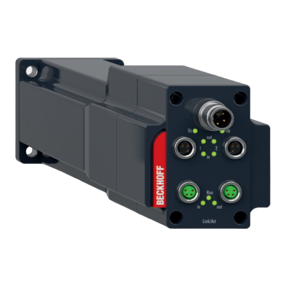
Page 39: Display
1 and 2 No supply voltage present at in- puts 1 and 2 Motor voltage 7.6.1.2 7.6.1.2 Up = status display of the power supply of the servo drive Status Peripheral voltage present No peripheral voltage present Version: 1.0 AMI8100 ───... - Page 40 Link/Act with in and out = display of the communication state Status Link: connection to the con- nected EtherCAT module; no communication Flashes Act: communication with con- nected EtherCAT module No connection to the connected EtherCAT module ─── AMI8100 Version: 1.0...
-
Page 41: Mechanical Installation
Impacts on the shaft im- pair the concentricity of the servo drive. Ensure adequate grounding via the protective conductor The thermal connection of the flange determines the power loss. Ensure adequate grounding via the protective conductor or the flange. Version: 1.0 AMI8100 ───... - Page 42 A-side; shaft output side of the servo drive. Oscillatory bearing movements < 180 ° shaft rotation are not permis- sible. Use the Beckhoff load/force calculator for a detailed calcula- tion of the bearing forces on the shaft. Servo drive...
- Page 43 ► Insert washer [3] with bolt [4] of strength class 8.8 and nut [5] into the locking thread [6] of the shaft ► Tighten nut [5] The output element is pulled onto the shaft by the nut. Version: 1.0 AMI8100 ───...
- Page 44 ► Screw puller [3] and intermediate disc [2] into the locking thread of the shaft ► Place the puller fully on the drive element [1] ► Pull the output element [1] with the puller [3] from the shaft ─── AMI8100 Version: 1.0...
-
Page 45: Electrical Installation
Beckhoff supplies pre-assembled connection cables. Mating con- nectors are not included in the scope of supply. For the selection of the necessary cables, refer to the Beckhoff documentation for the connecting cables [+]. In the documentation you will find a complete overview of the available cables and information on the technical data. - Page 46 Faults and malfunctions as well as exclusion of warranty can be the result. Beckhoff connection cables differ from one another in the method of laying, the type of connection and the core cross-section. In the ta- ble below you will find an assignment of the different connection ca- bles.
- Page 47 ► Push the plug [1] straight onto the socket [2] ► Make sure that the marking point [3] points upwards ► Screw thread [3] into the socket Version: 1.0 AMI8100 ───...
- Page 48 ► Push the plug [1] straight onto the socket [2] If present: ► Make sure that the marking point [3] points upwards ► Screw thread [3] into the socket ─── AMI8100 Version: 1.0...
-
Page 49: Connector Assignment
Electrical installation Connector assignment Beckhoff offers various power connectors, sensor connectors and feedback connectors. All plugs are IP65 rated. A protective conduc- tor connection according to VDE 0627 is provided on the housing. Power The following table shows the plug assignment on the motor side for the power connection: 9.2.1... -
Page 50: Commissioning
• Check protective measures against moving and live parts Configuration Beckhoff recommends the configuration of integrated servo drives of the AMI812x series in the Beckhoff TwinCAT 3 Drive Manager 2: • Build Project and Choose Target System • Implement devices by scanning or manually •... -
Page 51: Prerequisites During Operation
Place the machine or plant in a safe state Make sure that the rotor comes to a complete stop. When the holding brake [+] is released, the rotor moves without remanent torque. Rotating components can lead to serious in- juries. Version: 1.0 AMI8100 ───... -
Page 52: Maintenance And Cleaning
Use grease-dissolving and non-aggressive cleaning agents such as isopropanol for cleaning. You will also receive information about non-approved cleaning agents. Not applicable Cleaning agents Chemical formula 11.1.1 Aniline hydrochloride Bromine Sodium hypochlorite; bleaching NaCIO solution Mercury (II) chloride HgCl Hydrochloric acid ─── AMI8100 Version: 1.0... -
Page 53: Intervals
In case of damage and pressure drop: Replace shaft sealing ring Cables Regular intervals Perform visual inspection and check for damage If required: Replace cables 5 million bending cycles Replace cables Sockets 500 cycles In case of damage: Contact Beckhoff Service Version: 1.0 AMI8100 ───... -
Page 54: Accessories
A gear unit serves to transmit a moment of force or a torque and is used on the servo drive as an output element. Information on flange sizes for combinations of servo drive and gear unit can be found in the chapter: Type key. ─── AMI8100 Version: 1.0... -
Page 55: Decommissioning
Leaking oil can cause slips and falls, resulting in serious or fatal injury. Hot oil can cause severe burns. Do not remove components from the products Only Beckhoff Automation GmbH & Co. KG is permitted to remove components. Contact Beckhoff Service if you have any questions. -
Page 56: Disposal
The trans- 13.2.1 port costs are borne by the sender. Send the used devices with the note "For disposal" to: Beckhoff Automation GmbH & Co. KG "Service" Building Stahlstrasse 31 D-33415 Verl In addition, you have the option to contact a local certified specialist company for the disposal of used electrical and electronic appli- ances. -
Page 57: Guidelines And Standards
The servo drives do not fall within the scope of the 14.3 Machinery Directive. However, Beckhoff products are designed and eval- uated in full compliance with all relevant regulations for personal safety and use in a machine or system. The servo drives meet all the requirements of the Eurasian Economic Union. -
Page 58: Eu Conformity
Guidelines and Standards EU conformity Provision 14.4 Beckhoff Automation GmbH & Co KG will be pleased to provide you with EU declarations of conformity and manufacturer's declara- tions for all products on request. Please send your request to: info@beckhoff.com CCC conformity Export to Chinese Economic Area 14.5... -
Page 59: Index
53 Technical data 26 Motor Tightening torques Commissioning 50 Flange 41 Dismantling 55 Transport 32 Disposal 56 Electrical installation 45 Mechanical installation 41 Storage 32 Transport 32 Name plate 17 Operating Conditions 26 Ordering options 21 Version: 1.0 AMI8100 ───... - Page 61 More Information: www.beckhoff.com/AMI8100 Beckhoff Automation GmbH & Co. KG Hülshorstweg 20 33415 Verl Germany Phone: +49 5246 9630 info@beckhoff.com www.beckhoff.com...
Need help?
Do you have a question about the AMI8100 and is the answer not in the manual?
Questions and answers