
Related Manuals for Beckhoff AM8100


Summary of Contents for Beckhoff AM8100
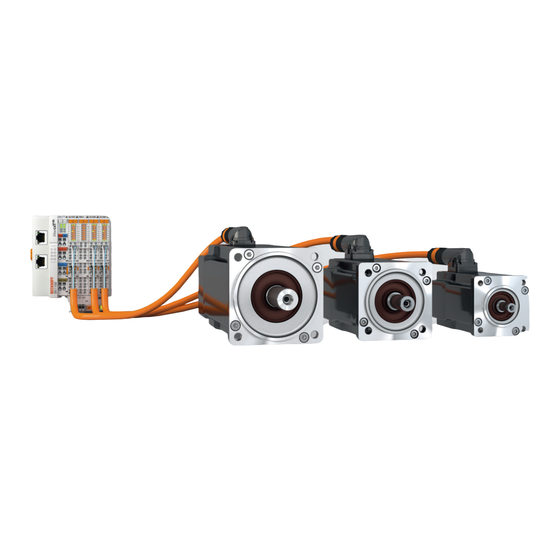
- Page 1 Operating instructions | EN AM8100 Synchronous servomotors for compact drive technology 3/4/2021 | Version: 2.2...
-
Page 3: Table Of Contents
Version numbers .......................... 6 Appropriate use .......................... 6 2 Guidelines and Standards ........................ 7 EU conformity ............................ 7 3 Safety ................................ 8 Safety instructions .......................... 8 Special safety instructions for AM8100 ..................... 9 4 Handling .............................. 10 Transport ............................ 10 Packaging ............................ 10 Storage ............................ 10 Maintenance / Cleaning ........................ 10 Disposal ............................ 10 5 Product overview............................. 11... - Page 4 Dimensional drawing ....................... 41 10.3.2 Dimensional drawing ....................... 42 10.3.3 Force diagram........................ 43 10.4 AM814x ............................ 44 10.4.1 Dimensional drawing ....................... 46 10.4.2 Dimensional drawing ....................... 47 10.4.3 Force diagram........................ 47 11 Appendix .............................. 48 11.1 Support and Service ........................ 48 Version: 2.2 AM8100...
-
Page 5: Foreword
EP1590927, EP1789857, EP1456722, EP2137893, DE102015105702 with corresponding applications or registrations in various other countries. ® EtherCAT is a registered trademark and patented technology, licensed by Beckhoff Automation GmbH, Germany Copyright © Beckhoff Automation GmbH & Co. KG, Germany. The reproduction, distribution and utilization of this document as well as the communication of its contents to others without express authorization are prohibited. -
Page 6: Version Numbers
Product properties Only the product properties specified in the current operating instructions are valid. Further information given on the product pages of the Beckhoff homepage, in emails or in other publications is not authoritative. Appropriate use Synchronous servomotors of the AM8100 series are designed as drives for handling equipment, textile machines, machine tools, packaging machines and similar machines with demanding requirements in terms of dynamics. -
Page 7: Guidelines And Standards
Danger for persons, the environment or equipment Servomotors from the AM8100 series are not products within the meaning of the EC Machinery Directive. Operation of the servomotors in machines or systems is only permitted once the machine or system manu- facturers has provided evidence of CE conformity of the complete machine or system. -
Page 8: Safety
All the components are supplied in particular hardware and software configurations appropriate for the application. Modifications to hardware or software configurations other than those described in the documentation are not permitted, and nullify the liability of Beckhoff Automation GmbH & Co. KG. Personnel qualification This description is only intended for trained specialists in control, automation and drive engineering who are familiar with the applicable national standards. -
Page 9: Special Safety Instructions For Am8100
• The machine manufacturer must prepare a hazard analysis for the machine, and must take appropriate measures to ensure that unexpected movements cannot lead to injury to persons or to objects. • Before working on the AM8100 the servomotor must be disconnected from the servo terminal and se- cured against switching on again. -
Page 10: Handling
• If the packaging is damaged, check the motor for visible damage. Inform the transport company and, if necessary, the manufacturer. Packaging • The max. stacking height by the servo motors AM8100 is 10 cardboard packaging. Storage • Climate category 2K3 according to EN 60721 •... -
Page 11: Product Overview
Product overview Product overview Scope of supply AM8100 Please check that the delivery includes the following items • Motor from the AM8100 series • Motor package leaflet (short info) AM8100 name plate Number Explanation AM8100 servomotor (with order identifier) Protection class specification... -
Page 12: Type Key
H = OCT multi-turn 24-bit, SIL 2 Holding brake ◦ 0 = no holding brake 1 = 24 V holding brake Versions ◦ 0 = Standard 1 = special version Not defined Connection ◦ 0 = rotatable angular connector iTec or M23-Speedtec Version: 2.2 AM8100... -
Page 13: Flange Sizes
Product overview 5.3.1 Flange sizes Motor sizes matching the adapter for gear unit mounting Beckhoff flange size AM3100 AM8000 AM8100 AM311x AM801x AM811x AM802x AM812x Exception AM312x AM812x-xxxx-9 AM803x AM813x AM804x AM814x AM8100 Version: 2.2... -
Page 14: Technical Description
Technical description Design of the motors The synchronous servomotors of the AM8100 series are brushless three-phase motors for demanding servo- applications. In conjunction with our digital servo drives they are particularly suitable for positioning tasks in industrial robots, machine tools, transfer lines etc. with demanding requirements in terms of dynamics and stability. -
Page 15: Standard Features
0_red Standard features 6.3.1 Style The basic style for the AM8100 synchronous servomotors is IM B5 according to DIN EN 60034-7. The permitted mounting positions are specified in the technical data. NOTE Motor damage To avoid liquid entry damaging the motor, fluids (i.e. used for cleaning purposes) must be removed from shaft when motor is mounted according to IM V3. -
Page 16: Flange
The motors are fitted with rotatable, angular connectors for the power supply and the feedback signals (only resolver). The mating connectors are not included in the scope of supply. We can supply preassembled feedback (only resolver) and power cables. Version: 2.2 AM8100... -
Page 17: Feedback System
A holding brake blocks the rotor in the de-energized state. The holding brake increases the motor length and the rotor moment of inertia. The holding brake cannot be retrofitted and is mounted on the B bearing side of the motor. 6.3.12 Pole number Motor Pole number AM811x AM812x AM813x AM814x AM8100 Version: 2.2... -
Page 18: Options
• Rated speed at rated supply voltage nn [rpm] • Moment of inertia of motor and load J [kgcm²] • Effective torque (calculated) Mrms [Nm] When calculating the required motors and servo terminals, observe the static load and the dynamic loads (acceleration/braking). Version: 2.2 AM8100... -
Page 19: Mechanical Installation
An incorrect setting can lead to the destruction of the motor, espe- cially with small Motors. • Check compliance the permitted radial and axial loads F and F .When using a toothed belt drive, the minimum permitted diameter of the pinion follows from the equation: AM8100 Version: 2.2... -
Page 20: Flange Mounts
Information on correct flange-mounting of the motors is provided below. Size Bore diameter Cheese-head screw Tightening torque Plain washer [mm] DIN EN ISO 4762 (8.8) [Nm] DIN EN ISO 7089 AM811x M4 x 16 Washer M4 DIN 127 AM812x M5x16 AM813x M5x16 AM814x M6x20 10.0 Version: 2.2 AM8100... -
Page 21: Electrical Installation
EMC shielding and earthing.Earth the mounting plate and motor housing. • Only use cables approved by Beckhoff for operating the AM8100 with the “one-cable technology” (OCT). • Route the power and control cables as separately as possible from one another (separation > 20 cm).This will improve the immunity of the system to electromagnetic interference.If a motor power cable... -
Page 22: Connection Technology
Beckhoff supplies prefabricated power and feedback cables. Mating connectors are not included in the scope of supply. For the selection of the necessary cables, refer to the Beckhoff documentation for the connecting cables. In the documentation you will find a complete overview of the available cables and information on the technical data. - Page 23 Electrical installation Choice of cable Beckhoff motor cables and feedback cables differ from one another in the method of laying, the type of connection and the core cross-section. The table below shows the assignment of the different Beckhoff cables to the matching servomotors and servo terminals.
-
Page 24: Connectors
5. Turn the iTec connector by hand into the correct position so that the marking points [3] are aligned Pin assignment Beckhoff offers various power connectors and feedback connectors. All plugs are IP65 rated. A protective conductor connection according to VDE 0627 is provided on the housing. -
Page 25: Feedback
The following tables show the connector assignment on the motor side: Resolver Pin assignment of M12 plug, 8-pin Resolver con- Contact Function Core identification nector SIN+ white SIN- brown COS+ green COS- yellow REF+ gray REF- pink AM8100 Version: 2.2... -
Page 26: Shielding Concept
Electrical installation Shielding concept Together with the shield busbar, the prefabricated cables from Beckhoff offer optimum protection against electromagnetic interference. Connection of the motor cable to the shield busbar Fasten the shield busbar supports (1) to the DIN rail (2). The DIN rail (2) must be in contact with the metallic rear wall of the control cabinet over a wide area. -
Page 27: Comissioning
• Carry out any further tests which are specifically required for your System. • Now commission the drive according to the commissioning instructions for the servo terminal. • In multi-axis systems, individually commission each drive unit (servo terminal/motor(s)). AM8100 Version: 2.2... -
Page 28: Troubleshooting
Check the plug connector Check cables Break in cable, cable crushed or similar Reading of error messages from Internal error OCT feedback Brake does not grip Required holding torque too high Check the design Brake faulty Replace motor Version: 2.2 AM8100... -
Page 29: Technical Data
Winding inductance L [mH] The winding inductance is the specification of the motor inductance as an average value over one revolution of the motor, on two powered phases at 1 kHz, taking into account the saturation of the motor. AM8100 Version: 2.2... -
Page 30: Am811X
◦ Nominal speed Nn [min-1] 4000 4500 3000 ◦ Rated torque M [Nm] 0.19 0.36 0.50 ◦ Power rating P ◦ Nominal current In [A] 2.71 4.65 Connection technology iTec iTec iTec Reference flange aluminum 230 mm x 130 mm x 10 mm Version: 2.2 AM8100... - Page 31 Optional holding brake [+] AM811x ◦ Holding torque at 120 °C M [Nm] ◦ Supply voltage U 24 +6 -10% ◦ Electrical power P ◦ Current at 120 °C I ◦ Release delay time t [ms] ◦ Application delay time t [ms] AM8100 Version: 2.2...
-
Page 32: Dimensional Drawing
Technical data 10.1.1 Dimensional drawing • All figures in millimeters Version: 2.2 AM8100... -
Page 33: Force Diagram
Technical data 10.1.2 Force diagram AM8100 Version: 2.2... -
Page 34: Am812X
◦ Rated current In [A] 12.5 14.6 Connection technology iTec iTec iTec iTec iTec M23- M23- Speedt Speedt Reference flange aluminum 230 mm x 130 mm x 10 mm Installation of a shaft seal ring leads to a reduction of the rated values. Version: 2.2 AM8100... - Page 35 Optional holding brake [+] AM812x ◦ Holding torque at 120 °C M [Nm] ◦ Supply voltage U 24;+6 % to -10 % ◦ Electrical power P ◦ Current I ◦ Release delay time t [ms] ◦ Application delay time t [ms] AM8100 Version: 2.2...
-
Page 36: Dimensional Drawing
Technical data 10.2.1 Dimensional drawing • All figures in millimeters • Illustration with F winding and J winding Version: 2.2 AM8100... - Page 37 Technical data 10.2.2 Dimensional drawing • All figures in millimeters • Illustration with N-winding Motor Z - brake AM8122 133.5 AM8123 155.5 Feather key • Center bore according to DIN 332-D AM8100 Version: 2.2...
-
Page 38: Force Diagram
Technical data 10.2.3 Force diagram Version: 2.2 AM8100... -
Page 39: Am813X
14.9 14.8 13.5 Connection technology iTec iTec iTec M23- iTec M23- M23- Speedt Speedt Speedt Reference flange aluminum 230 mm x 130 mm x 10 mm Installation of a shaft seal ring leads to a reduction of the rated values. AM8100 Version: 2.2... - Page 40 ◦ Supply voltage U 24 V DC +6% to-10% 24 V DC +6% to-10% ◦ Electrical power P ◦ Current at 120 °C I 0.33 0.36 ◦ Release delay time t [ms] ◦ Application delay time t [ms] Version: 2.2 AM8100...
-
Page 41: Dimensional Drawing
Technical data 10.3.1 Dimensional drawing • All figures in millimeters • Illustration with F winding and J winding AM8100 Version: 2.2... - Page 42 Technical data 10.3.2 Dimensional drawing • All figures in millimeters • Illustration with N-winding Motor Z - brake AM8131 AM8132 AM8133 Feather key • Center bore according to DIN 332-D Version: 2.2 AM8100...
-
Page 43: Force Diagram
Technical data 10.3.3 Force diagram AM8100 Version: 2.2... -
Page 44: Am814X
◦ Power rating P ◦ Nominal current In [A] 15.2 14.6 Connection technology iTec M23-Speedtec M23-Speedtec Reference flange aluminum 230 mm x 130 mm x 10 mm Installation of a shaft seal ring leads to a reduction of the rated values. Version: 2.2 AM8100... - Page 45 ◦ Holding torque at 120 °C M [Nm] ◦ Supply voltage U 24 V DC +6% to-10% ◦ Electrical power P ◦ Current at 120 °C I 0.54 ◦ Release delay time t [ms] ◦ Application delay time t [ms] AM8100 Version: 2.2...
-
Page 46: Dimensional Drawing
Technical data 10.4.1 Dimensional drawing • All figures in millimeters • Illustration with J-winding Version: 2.2 AM8100... -
Page 47: Force Diagram
Technical data 10.4.2 Dimensional drawing • All figures in millimeters • Illustration with N-winding Motor Z - brake AM8141 179.5 AM8142 209.5 • Center bore according to DIN 332-D Feather key [+] M6 x 16 10.4.3 Force diagram AM8100 Version: 2.2... -
Page 48: Appendix
Beckhoff's branch offices and representatives Please contact your Beckhoff branch office or representative for local support and service on Beckhoff products! The addresses of Beckhoff's branch offices and representatives round the world can be found on her internet pages: http://www.beckhoff.com You will also find further documentation for Beckhoff components there. - Page 50 More Information: Beckhoff Automation GmbH & Co. KG Hülshorstweg 20 33415 Verl Germany Phone: +49 5246 9630 info@beckhoff.com www.beckhoff.com...
Need help?
Do you have a question about the AM8100 and is the answer not in the manual?
Questions and answers