Table of Contents
Advertisement
Quick Links
Advertisement
Table of Contents

Related Manuals for Beckhoff AL8000


Summary of Contents for Beckhoff AL8000
- Page 1 Operating instructions | EN AL8000 Linear servomotors 11/17/2022 | Version 1.7...
-
Page 3: Table Of Contents
Version numbers............................... 7 Scope of the documentation .......................... 7 Staff qualification .............................. 8 Safety and instruction ............................. 10 Explanation of symbols........................... 10 Beckhoff Services ............................ 12 For your safety.............................. 13 Safety pictograms ............................ 13 General safety instructions .......................... 14 Product overview............................... 17 Linear servomotor............................ - Page 4 Maintenance and cleaning .......................... 102 Cleaning agents............................ 102 Decommissioning............................ 103 Disassembly .............................. 103 Disposal ................................ 104 Guidelines and Standards .......................... 105 Standards .............................. 105 Guidelines.............................. 105 Test centers .............................. 105 EU conformity ............................... 106 CCC conformity ............................ 106 ─── AL8000 Version: 1.7...
-
Page 5: Documentation Notes
Documentation notes Disclaimer Beckhoff products are subject to continuous further development. We reserve the right to revise the operating instructions at any time and without prior announcement. No claims for the modification of products that have already been supplied may be made on the basis of the data, diagrams and descriptions in these operating instruc- tions. - Page 6 • Use of untrained personnel • Use of unauthorized spare parts Copyright © Beckhoff Automation GmbH & Co. KG, Germany 1.1.4 The copying, distribution and utilization of this document as well as the communication of its contents to others without express autho- rization is prohibited.
-
Page 7: Version Numbers
Product features Only the product properties specified in the current operating in- structions are valid. Further information given on the product pages of the Beckhoff homepage, in emails or in other publications is not authoritative. Scope of the documenta- Apart from these operating instructions, the following documents are... -
Page 8: Staff Qualification
Trained specialists have received specific technical training and have specific technical knowledge and experience. Trained special- ists can: • apply relevant standards and directives • assess tasks that they have been assigned • recognize possible hazards • prepare and set up workplaces ─── AL8000 Version: 1.7... - Page 9 They are familiar with relevant standards and directives. Quali- fied electricians can: • independently recognize, avoid and eliminate sources of danger • implement specifications from the accident prevention regula- tions • assess the work environment • independently optimize and carry out their work Version: 1.7 AL8000 ───...
-
Page 10: Safety And Instruction
1.6.1 DANGER Failure to observe will result in serious or fatal injuries. WARNING Failure to observe may result in serious or fatal injuries. CAUTION Failure to observe may result in minor or moderate injuries. ─── AL8000 Version: 1.7... - Page 11 In the case of documentation on a monitor screen, use the zoom function to enlarge the QR code and reduce the distance. Version: 1.7 AL8000 ───...
-
Page 12: Beckhoff Services
Beckhoff and the worldwide partner companies offer comprehensive support and service. Support The Beckhoff Support offers technical advice on the use of individ- ual Beckhoff products and system planning. The employees support 1.7.1 you in the programming and commissioning of complex automation systems. -
Page 13: For Your Safety
Safety pictograms Beckhoff products feature safety pictograms, either on stickers or printed, which vary depending on the product. They serve to protect people and to prevent damage to the products. Safety pictograms must not be removed and must be legible for the user. -
Page 14: General Safety Instructions
People could be seriously or fatally injured by unpro- tected machine parts. Danger from magnetic fields Magnetic fields on individual components of the AL8000 linear ser- vomotors pose a risk to: • persons with cardiac pacemakers or implanted or external defib- rillators •... - Page 15 Do not touch hot surfaces Check the cooling of the surfaces with a thermometer. Do not touch the components during and immediately after operation. Allow the components to cool sufficiently after switching off. Version: 1.7 AL8000 ───...
- Page 16 De-energize and switch off components before working on them 2.2.3 Check the functionality of all safety-relevant devices. Secure the working environment. Secure the machine or plant against being in- advertently started up. Observe the chapter: "Decommissioning". ─── AL8000 Version: 1.7...
-
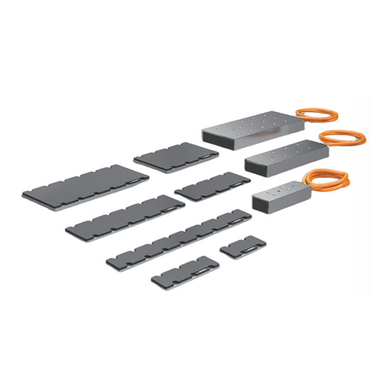
Page 17: Product Overview
Product overview Number Explanation Cable: power and temperature sensor Water cooling connection [+] Holes for locating pins Thread for mounting on the machine slide Primary component: coil part of the linear servomotor Secondary part: Magnetic plate Version: 1.7 AL8000 ───... -
Page 18: Linear Servomotor
Peak force Continuous force Maximum velocity Protection class Peak current Continuous current Nominal voltage Insulation class cURus approval WEEE compliance Country of manufacture UKCA marking Data matrix code; BIC = Beckhoff Identification Code CE conformity EAC approval ─── AL8000 Version: 1.7... - Page 19 1 = water cooling Winding letter A … Z S = special winding Feedback system 0 = without feedback Connection technology 0 = cable tail without plug 1 = cable tail with plug 0000 Not used Version: 1.7 AL8000 ───...
-
Page 20: Magnetic Plate
Magnetic plate Name plate 3.2.1 3.2.1 Number Explanation Article description Order number Serial number Beckhoff traceability number Length Width EAC approval CE conformity Country of manufacture Safety pictograms Barcode Data matrix code; BIC = Beckhoff Identification Code ─── AL8000 Version: 1.7... - Page 21 Product overview Needle pattern marking 3.2.2 3.2.2 Number Explanation Serial number, 10 digits Beckhoff BTN, 8 digits Version: 1.7 AL8000 ───...
- Page 22 Iron-core series 8 linear servomotors Series 5 = magnetic plate Overall width 2 = W2; 50 mm 4 = W4; 80 mm 6 = W6; 130 mm Overall length 1 = short 2 = medium 3 = long 0000 - 0000 Not used ─── AL8000 Version: 1.7...
-
Page 23: Product Characteristics
• Motor switch-off temperature at 100 °C Uniform linear motor width Within a width category, such as AL802x, the coil parts have identi- cal width and can therefore be operated together on one magnetic track and combined as desired. Version: 1.7 AL8000 ───... -
Page 24: Ordering Options
Water cooling 3.4.1 3.4.1 The coil parts of the AL8000 series are available with convection cooling or water cooling. The connection of a water cooling system enables a higher continuous force of the linear motor. This ordering option is available for coil parts of the following series: •... -
Page 25: Intended Use
Product overview Intended use The linear servomotors of the AL8000 series may only be operated for the intended activities defined in this documentation under the specified ambient conditions. The components are installed in electrical systems or machines. In- dependent operation of the components is not permitted. -
Page 26: Technical Data
Continuous current I RMS value of the continuous current at continuous force F Maximum velocity V [m/s] Maximum velocity of the linear motor. Force constant K [N/A] Ratio of force to current while maintaining the design air gap. ─── AL8000 Version: 1.7... - Page 27 Distance across a pole pair, north pole and south pole, of the mag- netic plate. Air gap [mm] Distance between magnetic plate and coil part. Must be observed during assembly to achieve the specified values of the linear motor. Version: 1.7 AL8000 ───...
-
Page 28: Data For Operation And Environment
Short-term or long-term operation outside of the specifications listed here may reduce the service life of the coil parts. Beckhoff products are designed for operation under certain environ- mental conditions, which vary according to the product. The follow- ing specifications must be observed for operation and environment in order to achieve the optimum service life of the products. - Page 29 Calculation of the performance data if the installation altitude ex- ceeds 1000 m: CA_red Ambient temperature and installation altitude Calculation of the power data when exceeding the specified limits: Ambient temperature > 40°C and installation altitude > 1000 m above sea level: CA_red Version: 1.7 AL8000 ───...
-
Page 30: Al802X
AX5x03 AX5x03 AX5x06 AX5x06 AX8000 AX8108/AX8206 The values are valid for a linear servomotor mounted on a metal surface that is equal to or larger than that of the motor, at a surface temperature of 20°C ─── AL8000 Version: 1.7... - Page 31 • All figures in millimeters 4.3.1 Hole: • 5 mm diameter, 4 mm depth for locating pin ISO 8734 Tapped hole: • M5 thread, 6 mm depth Elongated hole: • 5 x 0.5 mm diameter, 4 mm depth for locating pin ISO 8734 AL8021 4.3.1.1 4.3.1.1 Version: 1.7 AL8000 ───...
- Page 32 Technical data AL8022 4.3.1.2 4.3.1.2 ─── AL8000 Version: 1.7...
- Page 33 Technical data AL8024 4.3.1.3 4.3.1.3 AL8026 4.3.1.4 4.3.1.4 Version: 1.7 AL8000 ───...
- Page 34 Technical data AL802x alignment Alignment based on AL802x as an example 4.3.2 The figure shows the positioning of a coil part in relation to the magnetic track. ─── AL8000 Version: 1.7...
-
Page 35: Al852X Magnetic Plates
• 6 mm diameter for screw M5 DIN7984, short head • 5 mm diameter, 3.5 mm depth for locating pin with diameter 5 Elongated hole: • 5 mm x 0.5 mm diameter, 3.5 mm depth for locating pin with di- ameter 5 m6 AL8521 4.4.1.1 4.4.1.1 Version: 1.7 AL8000 ───... - Page 36 Technical data AL8522 4.4.1.2 4.4.1.2 ─── AL8000 Version: 1.7...
- Page 37 Technical data AL8523 4.4.1.3 4.4.1.3 Version: 1.7 AL8000 ───...
-
Page 38: Al804X
AX5x03 AX5x06 AX5x03 AX5x06 AX8000 AX8108/AX8206 The values are valid for a linear servomotor mounted on a metal surface that is equal to or larger than that of the motor, at a surface temperature of 20°C ─── AL8000 Version: 1.7... - Page 39 AX8108 AX8108 AX8108 AX8206 AX8206 AX8206 The values are valid for a linear servomotor mounted on a metal surface that is equal to or larger than that of the motor, at a surface temperature of 20°C Version: 1.7 AL8000 ───...
- Page 40 • 4x connections for water cooling channel Hole: • 5 mm diameter, 4 mm depth for locating pin ISO 8734 Tapped hole: • M5 thread, 6 mm depth Elongated hole: • 5 x 0.5 mm diameter, 4 mm depth for locating pin ISO 8734 AL8041 4.5.1.1 4.5.1.1 ─── AL8000 Version: 1.7...
- Page 41 Technical data AL8042 4.5.1.2 4.5.1.2 Version: 1.7 AL8000 ───...
- Page 42 Technical data AL8043 4.5.1.3 4.5.1.3 ─── AL8000 Version: 1.7...
- Page 43 Technical data AL8044 4.5.1.4 4.5.1.4 Version: 1.7 AL8000 ───...
- Page 44 Technical data AL8045 4.5.1.5 4.5.1.5 AL8046 4.5.1.6 4.5.1.6 ─── AL8000 Version: 1.7...
- Page 45 Technical data AL8048 4.5.1.7 4.5.1.7 Version: 1.7 AL8000 ───...
- Page 46 Technical data AL804x alignment Alignment based on AL804x as an example 4.5.2 The figure shows the positioning of a coil part in relation to the magnetic track. ─── AL8000 Version: 1.7...
-
Page 47: Al854X Magnetic Plates
• 6 mm diameter for screw M5 DIN7984, short head • 5 mm diameter, 3.5 mm depth for locating pin with diameter 5 Elongated hole: • 5 mm x 0.5 mm diameter, 3.5 mm depth for locating pin with di- ameter 5 m6 AL8541 4.6.1.1 4.6.1.1 Version: 1.7 AL8000 ───... - Page 48 Technical data AL8542 4.6.1.2 4.6.1.2 ─── AL8000 Version: 1.7...
- Page 49 The values are valid for a linear servomotor mounted on a metal surface that is equal to or larger than that of the motor, at a surface temperature of 20°C Dimensional drawings • All figures in millimeters 4.7.1 Hole: • 5 mm diameter, 4 mm depth for locating pin ISO 8734 Tapped hole: • M5 thread, 6 mm depth Version: 1.7 AL8000 ───...
- Page 50 Technical data Elongated hole: • 5 x 0.5 mm diameter, 4 mm depth for locating pin ISO 8734 AL8064 4.7.1.1 4.7.1.1 ─── AL8000 Version: 1.7...
- Page 51 Technical data AL8065 4.7.1.2 4.7.1.2 Version: 1.7 AL8000 ───...
- Page 52 Technical data AL806A 4.7.1.3 4.7.1.3 ─── AL8000 Version: 1.7...
-
Page 53: Al806X-0
Technical data AL806x-0 alignment Alignment based on AL806x-0 as an example 4.7.2 The figure shows the positioning of a coil part in relation to the magnetic track. Version: 1.7 AL8000 ───... - Page 54 The values are valid for a linear servomotor mounted on a metal surface that is equal to or larger than that of the motor, at a surface temperature of 20°C Dimensional drawings • All figures in millimeters 4.8.1 Water cooling: • 2x connections water cooling channel G1/8", 8 mm depth ─── AL8000 Version: 1.7...
- Page 55 Technical data Hole: • 5 mm diameter, 4 mm depth for locating pin ISO 8734 Tapped hole: • M5 thread, 6 mm depth Elongated hole: • 5 x 0.5 mm diameter, 4 mm depth for locating pin ISO 8734 AL8066-1 4.8.1.1 4.8.1.1 Version: 1.7 AL8000 ───...
- Page 56 Technical data AL806A-1 4.8.1.2 4.8.1.2 ─── AL8000 Version: 1.7...
- Page 57 Technical data AL806B-1 4.8.1.3 4.8.1.3 Version: 1.7 AL8000 ───...
- Page 58 Technical data AL806F-1 4.8.1.4 4.8.1.4 ─── AL8000 Version: 1.7...
- Page 59 Technical data AL806x-1 alignment Alignment based on AL806x-1 as an example 4.8.2 The figure shows the positioning of a coil part in relation to the magnetic track. Version: 1.7 AL8000 ───...
-
Page 60: Al856X Magnetic Plates
• 6 mm diameter for screw M5 DIN7984, short head • 5 mm diameter, 6 mm depth for locating pin with diameter 5 m6 Elongated hole: • 5 mm x 0.5 mm diameter, 6 mm depth for locating pin with diam- eter 5 m6 AL8561 4.9.1.1 4.9.1.1 ─── AL8000 Version: 1.7... - Page 61 Technical data AL8562 4.9.1.2 4.9.1.2 Version: 1.7 AL8000 ───...
-
Page 62: Scope Of Supply
Check the shipment for the following contents: When ordering a coil part: • AL8000 series coil part • 2x adhesive name plates • Translation of the original instructions; this documentation When ordering a magnetic plate: •... -
Page 63: Transport And Storage
• Use of the vendor's original packaging The table shows the maximum stacking height at which you may store and transport the coil parts on a pallet in the original packag- ing: Motor type Stacking height [pieces] AL802x AL804x AL806x Version: 1.7 AL8000 ───... -
Page 64: Transport
We recommend that the coil part is always lifted horizontally. Only lift and transport in a vertical position if absolutely necessary. Please refer to sections "AL806x horizontal and AL806x vertical", [Page 65] ─── AL8000 Version: 1.7... - Page 65 ► Screw eyebolts [1] into the outer adjacent threads on the outer edge Magnetic plates The following options are available for transporting a single mag- netic plate: 6.2.2 • Without aids, by hand in compliance with the legal requirements for the lifting of loads Version: 1.7 AL8000 ───...
-
Page 66: Long-Term Storage
The coil parts can be stored for shorter or longer periods. We al- ways recommend storing components in the original packaging. Ob- serve the conditions specified in chapter: "Transport and storage", [Page 63]. Ensure the storage space is vibration-free. ─── AL8000 Version: 1.7... -
Page 67: Technical Description
Travel path = 490 mm Length of coil part AL8041 = 93 mm Length of magnetic plate AL8542 = 288 mm Required number of magnetic plates: (490 mm + 93 mm)/288 = 2.02 magnetic plates < 3 magnetic plates are required Version: 1.7 AL8000 ───... - Page 68 Passive part of the end side B [mm] Effective range C [mm] Housing length D [mm] AL804x Name AL80 Passive part of the cable side A [mm] 15.5 17.5 22.5 Passive part of the end side B [mm] Effective range C [mm] ─── AL8000 Version: 1.7...
- Page 69 Housing length D [mm] Water-cooled coil part Name AL80 66-1 6A-1 6B-1 6F-1 Passive part of the cable side A [mm] 31.5 Passive part of the end side B [mm] Effective range C [mm] Housing length D [mm] Version: 1.7 AL8000 ───...
-
Page 70: Air Gap
Air gap The air gap is created between the bottom of the coil part and the top of the magnetic plate. The air gap for Beckhoff linear motors is 0.5 mm while maintaining the overall mounting height. Overall mounting height You can increase the overall mounting height and the associated air gap in case of tolerance deviations. - Page 71 The following diagram shows the continuous force in relation to the attractive force as a function of the air gap: 7.2.2 Position Definition Setpoint 1 Ideal air gap Curve 2 Attractive force F Curve 3 Continuous force F Version: 1.7 AL8000 ───...
-
Page 72: Protection Equipment
Protection equipment A temperature sensor LPTC-600 is installed in all coil parts of the AL8000 series. The LPTC-600 is integrated into the monitoring sys- tem of the servo drives for motors with preassembled plugs. Config- ure the servo drive according to the motor temperature warning at 80 °C and the switch-off temperature at 100 °C. -
Page 73: Coupling
By coupling two coil parts of the next smaller series, the force re- quired for the application can be achieved and thus the width of the magnetic track can be reduced. Version: 1.7 AL8000 ───... -
Page 74: Arrangement Of Coil Parts
AL8042-0Eyz AL8042-0Eyz AL8043-0Eyz AL8043-0Eyz AL8043-0Gyz AL8043-0Gyz AL8044-0Eyz AL8044-0Eyz AL8044-0Hyz AL8044-0Hyz AL8045-0Gyz AL8045-0Gyz AL8045-0Kyz AL8045-0Kyz AL8046-0Gyz AL8046-0Gyz AL8046-0Kyz AL8046-0Kyz AL8048-0Hyz AL8048-0Hyz AL8048-0Kyz AL8048-0Kyz AL806x-0xxx Motor 1 Motor 2 [mm] AL8064-0Fyz AL8064-0Fyz AL8064-0Kyz AL8064-0Kyz AL8065-0Hyz AL8065-0Hyz AL8065-0Kyz AL8065-0Kyz ─── AL8000 Version: 1.7... - Page 75 Motor 1 Motor 2 [mm] AL806A-0Kyz AL806A-0Kyz 1121 AL806A-0Qyz AL806A-0Qyz 1121 AL806x-1xxx Motor 1 Motor 2 [mm] AL8066-1Jyz AL8066-1Jyz AL8066-1Nyz AL8066-1Nyz AL806A-1Kyz AL806A-1Kyz 1137 AL806A-1Ryz AL806A-1Ryz 1137 AL806B-1Lyz AL806B-1Lyz 1233 AL806F-1Nyz AL806F-1Nyz 1617 AL806F-1Tyz AL806F-1Tyz 1617 Version: 1.7 AL8000 ───...
- Page 76 AL8044-0Eyz AL8044-0Eyz AL8044-0Hyz AL8044-0Hyz AL8045-0Gyz AL8045-0Gyz AL8045-0Kyz AL8045-0Kyz AL8046-0Gyz AL8046-0Gyz AL8046-0Kyz AL8046-0Kyz AL8048-0Hyz AL8048-0Hyz AL8048-0Kyz AL8048-0Kyz AL806x-0xxx Motor 1 Motor 2 [mm] AL8064-0Fyz AL8064-0Fyz AL8064-0Kyz AL8064-0Kyz AL8065-0Hyz AL8065-0Hyz AL8065-0Kyz AL8065-0Kyz AL806A-0Kyz AL806A-0Kyz 1124 AL806A-0Qyz AL806A-0Qyz 1124 ─── AL8000 Version: 1.7...
- Page 77 Coupling AL806x-1xxx Motor 1 Motor 2 [mm] AL8066-1Jyz AL8066-1Jyz AL8066-1Nyz AL8066-1Nyz AL806A-1Kyz AL806A-1Kyz 1134 AL806A-1Ryz AL806A-1Ryz 1134 AL806B-1Lyz AL806B-1Lyz 1230 AL806F-1Nyz AL806F-1Nyz 1614 AL806F-1Tyz AL806F-1Tyz 1614 Version: 1.7 AL8000 ───...
- Page 78 AL8044-0Eyz AL8044-0Eyz AL8044-0Hyz AL8044-0Hyz AL8045-0Gyz AL8045-0Gyz AL8045-0Kyz AL8045-0Kyz AL8046-0Gyz AL8046-0Gyz AL8046-0Kyz AL8046-0Kyz AL8048-0Hyz AL8048-0Hyz AL8048-0Kyz AL8048-0Kyz AL806x-0xxx Motor 1 Motor 2 [mm] AL8064-0Fyz AL8064-0Fyz AL8064-0Kyz AL8064-0Kyz AL8065-0Hyz AL8065-0Hyz AL8065-0Kyz AL8065-0Kyz AL806A-0Kyz AL806A-0Kyz 1079 AL806A-0Qyz AL806A-0Qyz 1079 ─── AL8000 Version: 1.7...
- Page 79 Coupling AL806x-1xxx Motor 1 Motor 2 [mm] AL8066-1Jyz AL8066-1Jyz AL8066-1Nyz AL8066-1Nyz AL806A-1Kyz AL806A-1Kyz 1099 AL806A-1Ryz AL806A-1Ryz 1099 AL806B-1Lyz AL806B-1Lyz 1008 1195 AL806F-1Nyz AL806F-1Nyz 1392 1579 AL806F-1Tyz AL806F-1Tyz 1392 1579 Version: 1.7 AL8000 ───...
-
Page 80: Electrical Connection
• All figures in millimeters Example 1: AL8042 and AL8042 with cables in opposite direc- tions This alignment of the coil parts enables the minimum distance be- tween the coil parts. ─── AL8000 Version: 1.7... - Page 81 Example 1: AL8042 and AL8042 with cables in opposite direc- tions = 208 mm M1M2 Offset = (208/16) MOD 3 = 1 Example 2: AL8042 and AL8042 with cables in opposite direc- tions = 192 mm M1M2 Offset = (192/16) MOD 3 = 0 Version: 1.7 AL8000 ───...
- Page 82 AL8043 39.5 23.5 AL8044 39.5 23.5 AL8045 39.5 23.5 AL8046 39.5 23.5 AL8048 44.5 23.5 AL8064-0xxx 38.5 24.5 AL8065-0xxx 38.5 24.5 AL806A-0xxx 43.5 24.5 AL8066-1xxx 53.5 24.5 AL806A-1xxx 53.5 24.5 AL806B-1xxx 53.5 24.5 AL806F-1xxx 53.5 24.5 ─── AL8000 Version: 1.7...
- Page 83 This will trigger the switch-off procedure in the servo drive in case of a critical tempera- ture rise in the poorly cooled coil part. Version: 1.7 AL8000 ───...
-
Page 84: Mechanical Installation
The following figure shows the values for evenness and parallelism 9.1.1 for the coil unit and the magnetic plate. Position Description Machine slide Coil part Magnetic plate Machine bed Please refer to Chapter "Air gap, section Overall mounting height", [Page 70] ─── AL8000 Version: 1.7... -
Page 85: Assembly
Failure to observe this may result in loss of force at the linear motor and loss of performance in the machine or system. Version: 1.7 AL8000 ───... - Page 86 ► Insert the screws [4] and tighten them crosswise from inside to outside Observe tightening torques: Screw quality = strength class 8.8 Screw M5 x 0.8 Recommended screw depth 5 mm Maximum screw depth 6 mm Tightening torque 6 Nm ─── AL8000 Version: 1.7...
- Page 87 Mechanical installation ► Place the assembled coil part including the machine carriage [5] on the guide carriage [6] ► Insert and tighten the screws [7] Version: 1.7 AL8000 ───...
- Page 88 Observe the alignment Align the magnetic plates identically. The Beckhoff logo must al- ways be on the same side. If this is not observed, the adjacent magnetic plates repel each other.
- Page 89 Maximum immersion in the mag- 3.2 mm 5.5 mm netic plate ► Check the alignment of the magnetic plate. Make sure that the Beckhoff logos are on the same side. ► Place the magnetic plate [4] on the locating pins [3] Version: 1.7 AL8000 ───...
- Page 90 ► Mount the other magnetic plates in the same way Once all components have been fitted and you start up the ma- chine or system: ► Remove all protective covers [3] on all magnetic plates ─── AL8000 Version: 1.7...
- Page 91 Only use suitable coolant Coolants are not included in the scope of delivery and cannot be procured from BECKHOFF. Operate the motor only with an ap- proved and suitable coolant. Consult your coolant manufacturer in order to obtain a suitable coolant.
- Page 92 Mechanical installation AL806x-1 Motor Continuous Flow rate Q Pressure drop power loss P Δp [l/min] [bar] AL8066-1xyz AL806A-1xyz 1206 AL806B-1xyz 1140 1.95 AL806F-1xyz 1710 All values valid for a temperature increase ΔT of 10 K ─── AL8000 Version: 1.7...
- Page 93 Mechanical installation Direction of flow 9.2.3.2 9.2.3.2 • AL804x: Water flow in the same direction • AL806x-1: Water flow as cooling circuit Version: 1.7 AL8000 ───...
- Page 94 ► Remove the plug on the opposite side of the coil part ► Screw the threaded push-in fittings [2] into the holes provided AL804x: ► Screw in the threaded push-in fittings on the opposite side of the coil part ─── AL8000 Version: 1.7...
- Page 95 Coil part Hose Inner diameter Outside diameter [mm] AL804x AL806x-1xxx ► Insert the cooling hoses [3] into the threaded push-in fittings AL804x: ► Connect cooling hoses at the opposite side of the coil part Version: 1.7 AL8000 ───...
-
Page 96: Verification
To check the smooth running of the machine slide, carry out the fol- lowing steps: ► Remove all tools from the machine or system ► Clean the magnetic track ► Move the machine slide carefully by hand and guide it along the entire length of the magnetic track ─── AL8000 Version: 1.7... -
Page 97: Electrical Installation
Cables Do not lay cable in drag chains 10.1.1 The cable of the AL8000 is firmly encapsulated with the linear mo- tor. It is part of the wear-free product. Do not lay the cable in a drag chain. A limited service life or damage to the linear motor is the result. -
Page 98: Connector Assignment
Electrical installation Connector assignment Beckhoff offers various power connectors and feedback connectors. All plugs are IP65 rated. 10.2 The following tables show the connector assignment: iTec® plug 10.2.1 10.2.1 Pin assignment cable diameter 1.0 mm² Contact Function Color Core identifi- cation... - Page 99 Electrical installation M40 Speedtec® plug 10.2.3 10.2.3 Pin assignment cable diameter 4 mm² Contact Function Color Core identifi- cation Black Black Black Green/yellow n.c. Temperature+/ White Temperature-/ Blue Version: 1.7 AL8000 ───...
-
Page 100: Commissioning
• Check protective measures against moving and live parts Configuration Beckhoff recommends using Beckhoff servo drives and motors and configuration with Beckhoff TwinCAT 3 Drive Manager 2 | TE5950. Carry out the instructions in the operating manual for servo drives: • Build Project and Choose Target System •... -
Page 101: Prerequisites During Operation
Place the machine or plant in a safe state Make sure that the motor comes to a complete stop. Uncontrolled movements of the coil units can lead to serious in- juries or damage to the system or machine. Version: 1.7 AL8000 ───... -
Page 102: Maintenance And Cleaning
Use grease-dissolving and non-aggressive cleaning agents such as isopropanol for cleaning. You will also receive information about non-approved cleaning agents. Not applicable Cleaning agents Chemical formula 12.1.1 Aniline hydrochloride Bromine Sodium hypochlorite; bleaching NaCIO solution Mercury (II) chloride HgCl Hydrochloric acid ─── AL8000 Version: 1.7... -
Page 103: Decommissioning
• If present: Remove the water cooling • Disconnect the electrical connector • Remove the machine slide from guide rails • Unscrew and remove the bolts • Separate the coil part from the machine slide • Remove the locating pins Version: 1.7 AL8000 ───... -
Page 104: Disposal
The trans- 13.2.1 port costs are borne by the sender. Send the used devices with the note "For disposal" to: Beckhoff Automation GmbH & Co. KG "Service" Building Stahlstrasse 31 D-33415 Verl In addition, you have the option to contact a local certified specialist company for the disposal of used electrical and electronic appli- ances. -
Page 105: Guidelines And Standards
Guidelines and Standards Test procedures and certifications vary by product. Beckhoff linear servomotors of the AL8000 series are certified and tested according to the following directives and standards. Standards EN 60034-1:2010+Corr.:2010 "Rotating electrical machines – Rating and performance" 14.1 RoHS: EN 50581:2012 "Technical documentation for the assessment of electrical and elec-... -
Page 106: Eu Conformity
CCC conformity Export to Chinese Economic Area 14.5 Beckhoff linear motors of the AL8000 series are not subject to the China Compulsory Certificate; CCC. The products are exempt from this certification and can be exported to the Chinese economic area. - Page 108 More Information: www.beckhoff.com/al8000 Beckhoff Automation GmbH & Co. KG Hülshorstweg 20 33415 Verl Germany Phone: +49 5246 9630 info@beckhoff.com www.beckhoff.com...
Need help?
Do you have a question about the AL8000 and is the answer not in the manual?
Questions and answers