Beckhoff AMP8000 Operating Instructions Manual
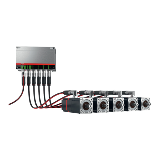
Distributed servo drives
Hide thumbs
Also See for AMP8000:
- Operating instructions manual (107 pages) ,
- Operating instructions manual (109 pages)

Subscribe to Our Youtube Channel
Related Manuals for Beckhoff AMP8000


Summary of Contents for Beckhoff AMP8000
- Page 1 Operating instructions | EN AMP8000 and AMP8500 Distributed servo drives 2024-10-01 | Version 2.0.0...
-
Page 3: Table Of Contents
1.1.4 Copyright ..........................Version numbers ..........................Scope of the documentation ......................Staff qualification..........................10 Safety and instruction......................... 12 Explanation of symbols ........................12 Beckhoff Services ..........................14 1.7.1 Support services........................14 1.7.2 Training offerings........................14 1.7.3 Service offerings........................14 1.7.4 Headquarters Germany...................... - Page 4 AMP80xx, AMP85xx distributed servo drive ................79 8 Mechanical installation ..........................80 Preparation............................80 8.1.1 Drilling pattern ......................... 82 Modules.............................. 84 8.2.1 Power supply modules and coupling modules ................ 84 8.2.2 Power supply module and distribution module................ 87 ─── AMP8000 and AMP8500 Version: 2.0.0...
- Page 5 Assembly tool AF27 ........................... 119 13 Decommissioning ............................120 13.1 Disassembly............................120 13.2 Disposal ............................. 121 13.2.1 Returning to the vendor......................121 14 Guidelines and Standards .......................... 122 14.1 Standards............................122 14.2 Guidelines ............................123 Version: 2.0.0 AMP8000 and AMP8500 ───...
- Page 6 Table of contents 14.2.1 Electrical isolation........................123 14.3 EU conformity............................. 124 14.4 CCC conformity..........................124 14.5 UL certification ........................... 125 14.5.1 USA and Canada ........................125 Index ................................126 ─── AMP8000 and AMP8500 Version: 2.0.0...
-
Page 7: Documentation Notes
Documentation notes 1 Documentation notes 1.1 Disclaimer Beckhoff products are subject to continuous further development. We reserve the right to revise the operating instructions at any time and without prior announcement. No claims for the modification of products that have already been supplied may be made on the basis of the data, diagrams and descriptions in these operating instruc- tions. -
Page 8: Limitation Of Liability
• Use of untrained personnel • Use of unauthorized spare parts 1.1.4 Copyright © Beckhoff Automation GmbH & Co. KG, Germany The copying, distribution and utilization of this document as well as the communication of its contents to others without express autho- rization is prohibited. -
Page 9: Version Numbers
Product features Only the product properties specified in the current operating in- structions are valid. Further information given on the product pages of the Beckhoff homepage, in emails or in other publications is not authoritative. 1.3 Scope of the documentation... -
Page 10: Staff Qualification
Trained special- ists can: • apply relevant standards and directives • assess tasks that they have been assigned • recognize possible hazards • prepare and set up workplaces ─── AMP8000 and AMP8500 Version: 2.0.0... - Page 11 • independently recognize, avoid and eliminate sources of danger • implement specifications from the accident prevention regula- tions • assess the work environment • independently optimize and carry out their work Version: 2.0.0 AMP8000 and AMP8500 ───...
-
Page 12: Safety And Instruction
This symbol indicates information, tips, and notes for handling the product or the software. Examples This symbol shows examples of how to use the product or software. Required tool This symbol indicates a tool that is required for the following steps. ─── AMP8000 and AMP8500 Version: 2.0.0... - Page 13 Required accessories [+] This symbol shows the accessories required for the following steps. The accessories are not included in the scope of delivery and can be ordered from Beckhoff. Assembly material required This symbol shows the assembly material required for the following steps.
-
Page 14: Beckhoff Services
+49 5246 963-157 support@beckhoff.com www.beckhoff.com/en-en/support/our-support-services/ 1.7.2 Training offerings Training in Germany takes place at the Beckhoff branches or, after consultation, at the customer's premises. Beckhoff offers both face- to-face and online training courses. +49 5246 963-5000 training@beckhoff.com www.beckhoff.com/en-en/support/training-offerings/ 1.7.3 Service offerings... -
Page 15: Headquarters Germany
Hülshorstweg 20 33415 Verl, Germany +49 5246 963-0 info@beckhoff.com www.beckhoff.com/en-en/ A detailed overview of the Beckhoff locations worldwide can be found at: www.beckhoff.com/en-en/company/global-presence/ 1.7.5 Downloadfinder In the Download finder you will find configuration files, technical doc- umentation and application reports to download. -
Page 16: For Your Safety
2.1 Safety pictograms You will find safety symbols on Beckhoff products and packaging. The symbols may be glued, printed, or lasered on and may vary de- pending on the product. They serve to protect people and to prevent damage to the products. -
Page 17: Amp8805 Distribution Module
60 °C. Allow the module housing to cool down for at least 15 minutes. 2.1.3 AX883x coupling module Warning of high voltage! The DC link on the coupling modules can have a life-threatening voltage of over 848 V Version: 2.0.0 AMP8000 and AMP8500 ───... -
Page 18: Amp80Xx, Amp85Xx Distributed Servo Drive
60 °C on the motor housing. Allow the motor housing to cool for at least 15 minutes. Avoid shocks to the shaft Impacts on the shaft can cause the maximum permissible axial and radial values to be exceeded. Optical encoder systems can thus be destroyed. ─── AMP8000 and AMP8500 Version: 2.0.0... -
Page 19: General Safety Instructions
Observe tightening torques Mount and repeatedly check connections and components, comply- ing with the prescribed tightening torques. Use the original packaging only Use the original packaging for dispatch, transportation, storage and packing. Version: 2.0.0 AMP8000 and AMP8500 ───... -
Page 20: During Operation
De-energize and switch off components before working on them Check the functionality of all safety-relevant devices. Secure the working environment. Secure the machine or plant against being in- advertently started up. Observe and comply with the chapter: "De- commissioning", [Page 120]. ─── AMP8000 and AMP8500 Version: 2.0.0... -
Page 21: Product Overview
X20 and X21: fieldbus output for EtherCAT P; M8 Display of the status LEDs Pressure compensation element Ground connection X40 to X44: AMP8000 system output B23 Only for AMP8620-2005-02x0 [+]: X71: connection for external braking resistor X01: connection of the supply network Version: 2.0.0... -
Page 22: Name Plate Amp8620
Fax. : + 49 52 46 / 9 63 - 198 Automation GmbH & Co. KG Germany www.Beckhoff.com info@beckhoff.com Item number Explanation Product name Order number Beckhoff Traceability Number, BTN Input voltage Input rated current Input frequency Output voltage Output rated current Output control voltage Maximum output control current... -
Page 23: Type Key Amp8620
0 = no braking resistor 1 = mounted braking resistor 2 = external braking resistor Input voltage range 0 = three-phase 400 …480 -20% +20% 1 = single-phase 120 …240 or three-phase 230 …480 -20% Not defined Version: 2.0.0 AMP8000 and AMP8500 ───... -
Page 24: Amp8805 Distribution Module
Product overview 3.2 AMP8805 distribution module Item number Explanation Housing X20: fieldbus output EtherCAT P; M8 Status LEDs Pressure compensation elements Ground connection X40 to X44: AMP8000 system output B23 X02: AMP8000 system input B23 ─── AMP8000 and AMP8500 Version: 2.0.0... -
Page 25: Name Plate Amp8805
Product overview 3.2.1 Name plate AMP8805 Item number Explanation Product name Order number Beckhoff Traceability Number; BTN Input voltage Input rated current Output voltage Output rated current Output control voltage Maximum output control current Maximum ambient temperature Protection class EAC approval EtherCAT P logo... -
Page 26: Type Key Amp8805
Number of M8-EtherCAT P outputs 1 = 1 output Not defined DC link voltage 0 = 430…848 V 1 = 155…848 V Not defined Version 0 = standard Nominal input current 0 = 20 A Not defined Not defined ─── AMP8000 and AMP8500 Version: 2.0.0... -
Page 27: Ax883X Coupling Module
EtherCAT connection AX bridge: quick coupling 24 V AX-Bridge: quick coupling of the DC link and the functional earth AX8832: X02: AMP8000 system output; L/A LED AX8832: X01: AMP8000 system output; L/A LED AX8831: X01: AMP8000 system output; L/A LED Grounding bolt AX bridge: DC link;... -
Page 28: Name Plate Ax883X
Ip20 E195162 Item number Explanation Product name Order number Beckhoff Traceability Number; BTN Input supply Maximum DC link voltage / nominal output current Output control voltage / output control current Maximum ambient temperature Protection class EtherCAT conformity cURus approval... -
Page 29: Amp80Xx, Amp85Xx Distributed Servo Drive
Product overview 3.4 AMP80xx, AMP85xx distributed servo drive Item number Explanation Housing Radial shaft-sealing ring [+] X02: AMP8000 system input B23 Status LEDs: Link/Activity, Run, AXIS Motor shaft Version: 2.0.0 AMP8000 and AMP8500 ───... -
Page 30: Name Plate Amp80Xx, Amp85Xx
Maximum input voltage and power Ambient temperature Standstill torque Nominal speed at 400 V AC supply voltage Protection class cURus approval EtherCAT conformity EAC approval TÜV test mark DataMatrix code with Beckhoff TN CE conformity Disposal according to WEEE directive ─── AMP8000 and AMP8500 Version: 2.0.0... -
Page 31: Type Key Amp80Xx, Amp85Xx
4 = multi-turn absolute encoder, resolution 24-bit, TwinSAFE Safe Motion Holding brake 0 = without holding brake 1 = with holding brake 2 = with holding brake and M8 plug for manual brake release Version: 2.0.0 AMP8000 and AMP8500 ───... -
Page 32: Product Characteristics
Product overview 3.5 Product characteristics No modification of the ma- The AMP8000 can be mounted instead of a standard servomotor of chine design the AM8000 and AM8500 series without modifying the machine de- sign, since only the overall length has been changed. All other di- mensions remain unchanged. - Page 33 3000 rpm with a maximum of three times the in- trinsic inertia of the motor. These maximum values may vary due to increased load inertia. The function check of the holding brake can be performed with a torque wrench or with TwinCAT Scope. Version: 2.0.0 AMP8000 and AMP8500 ───...
-
Page 34: Ordering Options
Communication takes place via the Safety over EtherCAT FSoE protocol according to IEC 61784-3-12. Information on commissioning and device replacement For commissioning and device replacement, follow the instructions in the operating manual AMP8911 – TwinSAFE card for the AMP8000 distributed servo drive. Order identifier Safety functions AMP80xx-xx1x Stop functions... - Page 35 Safely-limited position Safe cam Safely-limited increment Acceleration functions Safe acceleration range Safe maximum acceleration Direction of rotation functions SDIp Safe direction positive SDIn Safe direction negative Brake functions Safe brake control Safe brake test Version: 2.0.0 AMP8000 and AMP8500 ───...
-
Page 36: Feather Key
3.6.4 Connection for manual release of the holding brake The holding brake can be released for service purposes via the holding brake manual control connection. The AMP8000 motor has an additional M8 connection which is connected to an upstream 24 V DC power supply via the corresponding service. -
Page 37: Sealing Air Connection
Compressed air re- According to DIN ISO 8573-1 Class 3:2010 quirement [A:B:C] Operating pressure 0.1 ± 0.05 bar Maximum pressure 0.3 bar Air connection Quick-release coupling Required air line e.g. PA hose 6 mm x 4 mm Version: 2.0.0 AMP8000 and AMP8500 ───... -
Page 38: Intended Use
Any type of use that exceeds the permissible values from the techni- cal data is regarded as inappropriate and is thus prohibited. The distributed servo drive system of the AMP8000 series is not suitable for use in the following areas: •... -
Page 39: Dual Use
599 Hz according to the current state of production and is therefore not subject to export control. This rotary field frequency limited at a maximum of 599 Hz is suffi- cient to operate all distributed servo drives in the AMP8000 series at full power. Version: 2.0.0 AMP8000 and AMP8500 ───... -
Page 40: Technical Data
Measurement of the acceleration capacity of the motor. For exam- [kgcm²] ple, at J the acceleration time t from 0 to 3000 rpm can be calcu- lated based on the following formula: with M in Nm and J in kgcm ─── AMP8000 and AMP8500 Version: 2.0.0... - Page 41 Release delay time / applica- Specification of the response times of the holding brake [+] when tion delay time for the operated at the nominal voltage. holding brake t [ms]/t [ms] Version: 2.0.0 AMP8000 and AMP8500 ───...
-
Page 42: Data For Operation And Environment
Only operate the AMP8000 distributed servo drive system under specified conditions Operate the AMP8000 distributed servo drive system only in ac- cordance with the specifications for operation and the environ- ment listed in this chapter. This ensures a long service life and proper operation. -
Page 43: Amp8620 Power Supply Modules
The output current of the integrated power supply is divided between the power outputs and the EtherCAT P outputs. Mechanical data AMP8620 -2005-0000 -2005-0100 -2005-0200 Weight [kg] 8.70 Protection rating IP65 Protection rating conforms NEMA 12 to UL Version: 2.0.0 AMP8000 and AMP8500 ───... - Page 44 Continuous braking power 1600 The output current of the integrated power supply is divided between the power outputs and the EtherCAT P outputs. Mechanical data AMP8620 -2005-0010 -2005-0110 -2005-0210 Weight [kg] 8.70 Protection rating IP65 ─── AMP8000 and AMP8500 Version: 2.0.0...
- Page 45 Technical data Mechanical data AMP8620 -2005-0010 -2005-0110 -2005-0210 Protection rating conforms NEMA 12 to UL Version: 2.0.0 AMP8000 and AMP8500 ───...
-
Page 46: Dimensional Drawing Amp8620
Technical data 4.3.1 Dimensional drawing AMP8620 • All figures in millimeters 4.3.1.1 AMP8620-2005-00x0 ─── AMP8000 and AMP8500 Version: 2.0.0... - Page 47 Technical data 4.3.1.2 AMP8620-2005-01x0 Version: 2.0.0 AMP8000 and AMP8500 ───...
- Page 48 Technical data 4.3.1.3 AMP8620-2005-02x0 ─── AMP8000 and AMP8500 Version: 2.0.0...
-
Page 49: Amp8805 Distribution Modules
The output current of the integrated power supply is divided between the power outputs and the EtherCAT P output. Mechanical data AMP8805-1000-0000 Weight [kg] 4.50 Protection rating IP65 Protection rating conforms NEMA 12 to UL Version: 2.0.0 AMP8000 and AMP8500 ───... - Page 50 The output current of the integrated power supply is divided between the power outputs and the EtherCAT P output. Mechanical data AMP8805-1010-0000 Weight [kg] 4.50 Protection rating IP65 Protection rating conforms NEMA 12 to UL ─── AMP8000 and AMP8500 Version: 2.0.0...
-
Page 51: Dimensional Drawing Amp8805
Technical data 4.4.1 Dimensional drawing AMP8805 • All figures in millimeters 4.4.1.1 AMP8805-1000-0000 Version: 2.0.0 AMP8000 and AMP8500 ───... -
Page 52: Ax883X Coupling Module
Nominal output current 24 V DC [A 2 x 12 DC link voltage [V max. 848 Mechanical data AX8831 AX8832 Weight [kg] 1.80 1.90 Protection rating IP20 IP20 4.5.1 Dimensional drawing AX883x • All figures in millimeters 4.5.1.1 AX8831-0000-0000 ─── AMP8000 and AMP8500 Version: 2.0.0... - Page 53 Technical data 4.5.1.2 AX8832-0000-0000 Version: 2.0.0 AMP8000 and AMP8500 ───...
-
Page 54: Amp803X, Amp853X Distributed Servo Drive
4.40 5.20 Flange according to IEC DIN 42955 Tolerance class Protection rating Standard housing version IP65 Standard shaft feedthrough IP54 / IP20 in mounting position V3 version Shaft feedthrough with radial IP65 shaft-sealing ring ─── AMP8000 and AMP8500 Version: 2.0.0... - Page 55 Control voltage input [V 18 to 31 Current consumption of the 0.19 control voltage [A With holding brake Control voltage input [V 21.6 to 25.4 Current consumption of the 0.52 0.55 0.52 0.55 control voltage [A Version: 2.0.0 AMP8000 and AMP8500 ───...
-
Page 56: Dimensional Drawing Amp803X, Amp853X
4.6.1 Dimensional drawing AMP803x, AMP853x • All figures in millimeters Motor type Z with holding brake AMP8031-xxxx-1001 225.0 mm 264.5 mm AMP8032-xxxx-1001 250.5 mm 290.0 mm AMP8033-xxxx-1001 276.0 mm 325.0 mm AMP8531-xxxx-1001 264.5 mm 290.0 mm AMP8532-xxxx-1001 290.0 mm 325.0 mm AMP8533-xxxx-1001 325.0 mm 360.0 mm ─── AMP8000 and AMP8500 Version: 2.0.0... -
Page 57: Amp804X, Amp854X Distributed Servo Drive
7.10 Flange according to IEC DIN 42955 Tolerance class Protection rating Standard housing version IP65 Standard shaft feedthrough IP54 / IP20 in mounting position V3 version Shaft feedthrough with ra- IP65 dial shaft-sealing ring Version: 2.0.0 AMP8000 and AMP8500 ───... - Page 58 Without holding brake Control voltage input [V 18 to 31 Current consumption of 0.19 the control voltage [A With holding brake Control voltage input [V 21.6 to 25.4 Current consumption of 0.73 the control voltage [A ─── AMP8000 and AMP8500 Version: 2.0.0...
-
Page 59: Dimensional Drawing Amp804X, Amp854X
4.7.1 Dimensional drawing AMP804x, AMP854x • All figures in millimeters Motor type Z with holding brake AMP8041 225.5 mm 273.0 mm AMP8042 255.5 mm 303.0 mm AMP8043 285.5 mm 333.0 mm AMP8541 273.0 mm 303.0 mm AMP8542 303.0 mm 333.0 mm AMP8543 333.0 mm 363.0 mm Version: 2.0.0 AMP8000 and AMP8500 ───... -
Page 60: Amp805X, Amp855X Distributed Servo Drive
10.2 Weight with brake [kg] 6.30 9.80 11.50 11.2 Flange according to IEC DIN 42955 Tolerance class Protection rating Standard housing version IP65 Standard shaft IP54 / IP20 in mounting position V3 feedthrough version ─── AMP8000 and AMP8500 Version: 2.0.0... - Page 61 Control voltage input [V 18 to 31 Current consumption of 0.19 the control voltage [A With holding brake Control voltage input [V 21.60 to 25.40 Current consumption of 0.73 0.70 1.19 0.73 the control voltage [A Version: 2.0.0 AMP8000 and AMP8500 ───...
-
Page 62: Dimensional Drawing Amp805X, Amp855X
4.8.1 Dimensional drawing AMP805x, AMP855x • All figures in millimeters Motor type Z with holding brake AMP8051 230.0 mm 277.0 mm AMP8052 263.0 mm 310.0 mm AMP8053 296.0 mm 345.0 mm AMP8054 329.0 mm 378.0 mm AMP8551 277.0 mm 310.0 mm AMP8552 310.0 mm 345.0 mm AMP8553 345.0 mm 378.0 mm ─── AMP8000 and AMP8500 Version: 2.0.0... -
Page 63: Scope Of Supply
The scope of delivery always includes the following documents: Translation of the original in- Short information structions AMP8620 and AX883x AMP8805 and AMP8000 Depending on the application, the scope of delivery may consist of different components. Please check the delivery: Components Connector AMP8620-2005-02x0 •... -
Page 64: Packaging
The following products are supplied in packaging size D: • AMP8033-xxx1 • AMP8041-xxx1, AMP8042-xxx1, AMP8043-xxx1 • AMP8051-xxx0, AMP8052-xxx0, AMP8053-xxx0 • AMP8051-xxx1, AMP8052-xxx1, AMP8053-xxx1 • AMP8533-xxx0 • AMP8532-xxx1, AMP8533-xxx1 • AMP8541-xxx1, AMP8542-xxx1, AMP8543-xxx1 • AMP8551-xxx0, AMP8552-xxx0, AMP8553-xxx0 ─── AMP8000 and AMP8500 Version: 2.0.0... - Page 65 Scope of supply Packaging E Size of packaging E: 300 x 300 x 750 (h x w x d in mm) The following products are supplied in packaging size E: • AMP8553-xxx1 Version: 2.0.0 AMP8000 and AMP8500 ───...
-
Page 66: Transport And Storage
Transport and storage 6 Transport and storage WARNING Protect AMP8000 from damage During transport and storage, protect the distributed servo drive system from damage and observe the conditions. Damage may result in hazardous voltages being present on the housing or exposed components and can lead to serious or even fatal injuries. - Page 67 14 per layer; 7 layers per pallet AMP804x-xxxx AMP853x-xxxx AMP8531-xxx1 AMP8541-xxx0 AMP8033-xxx1 9 per layer; 6 layers per pallet AMP804x-xxx1 AMP805x-xxxx AMP8533-xxx0 AMP853x-xxx1 AMP854x-xxx0 AMP854x-xxx1 AMP8054-xxx1 4 per layer; 4 layers per pallet AMP8553-xxx1 Version: 2.0.0 AMP8000 and AMP8500 ───...
-
Page 68: Transport
Legal regulations for the lifting of loads When transporting distributed servo drive systems, comply with the legal regulations on lifting loads for employees. Transport of the components of the distributed servo drive system of the AMP8000 series without aids. ─── AMP8000 and AMP8500 Version: 2.0.0... -
Page 69: Long-Term Storage
5 years Exceeding the specified maximum storage time can lead to a change in the properties of the components used in the distributed servo drive system and may damage them during operation. Version: 2.0.0 AMP8000 and AMP8500 ───... -
Page 70: Technical Description
The standard installation position of the modules in the machine or in the control cabinet is the vertical installation position with the con- nections facing downwards. AMP8620-2005-00x0 and AMP8620-2005-02x0 • No derating due to installation position • All figures in millimeters ─── AMP8000 and AMP8500 Version: 2.0.0... - Page 71 Technical description AMP8620-2005-01x0 • No derating due to installation position • All figures in millimeters Version: 2.0.0 AMP8000 and AMP8500 ───...
- Page 72 Technical description AMP8805 • No derating due to installation position • All figures in millimeters ─── AMP8000 and AMP8500 Version: 2.0.0...
- Page 73 Technical description AX883x • No derating due to installation position Version: 2.0.0 AMP8000 and AMP8500 ───...
-
Page 74: Installation Position Amp80Xx, Amp85Xx Distributed Servo Drive
If you do not observe the maintenance intervals, the motor may overheat depending on the installation position. Ingress and leak- age of liquids may damage the motor. The standard installation position of the motors is the design IM B5 according to DIN 60034-7. ─── AMP8000 and AMP8500 Version: 2.0.0... -
Page 75: Dimensioning
Technical description 7.3 Dimensioning In the following you will find important information about the cable lengths. 7.3.1 Cable lengths Various cable lengths apply to the AMP8000 distributed servo drive system. Module combination Maximum cable length AMP8620 with AMP8805 AMP8805 with AMP8805... -
Page 76: Wide Voltage Range
Technical description 7.4 Wide voltage range You have the option of operating the AMP8000 distributed servo drive system worldwide on different voltage systems thanks to the wide voltage range of the AMP8620 power supply modules. All networks with a grounded center point are permitted; TT / TN. -
Page 77: Display
Technical description 7.5 Display The LEDs of the AMP8000 distributed servo drive system provide information on the operating state. There are different light se- quences for each operating state. The following section provides in- formation on the meaning of the various status LEDs on the compo- nents of the AMP8000 distributed servo drive system. -
Page 78: Amp8805 Distribution Module
L/A = Link/Activity to display the communication state Status LINK: connection to the connected EtherCAT module Flashes ACT: communication with connected EtherCAT module No connection to the connected EtherCAT module Illustration: LED display [1] on the coupling module ─── AMP8000 and AMP8500 Version: 2.0.0... -
Page 79: Amp80Xx, Amp85Xx Distributed Servo Drive
The axis is released and error-free Flashes quickly The axis is disabled and is being initialized Flashes slowly The axis is disabled and error-free No 24 V connection or the axis is in the EtherCAT operating state INIT or Error Version: 2.0.0 AMP8000 and AMP8500 ───... -
Page 80: Mechanical Installation
Note that when dimensioning you may have to mount input filters, mains chokes and brake resistors for your application. Appropriate space should be provided for these components, so that adequate ventilation is ensured. ─── AMP8000 and AMP8500 Version: 2.0.0... - Page 81 The following figure shows recommended dimensions that you should observe when mounting the coupling module on the machine or plant: Item number Explanation Machine or plant Conductive and galvanized mounting plate Cable channel Cable channel Version: 2.0.0 AMP8000 and AMP8500 ───...
-
Page 82: Drilling Pattern
8.1.1.1 Power supply modules and distribution modules Information is given in the figure below on how to make tapped holes in accordance with the drilling pattern. ─── AMP8000 and AMP8500 Version: 2.0.0... - Page 83 Mechanical installation 8.1.1.2 Coupling modules Beckhoff universal drilling pattern You have the possibility – at any time and without having to drill new holes – to change the configuration of the coupling modules if you provide the mounting plate with the universal drilling pattern.
-
Page 84: Modules
► Guide the screws [1] through the rectangular cut-outs in the module housing [2] ► Screw all the screws tight in the elongated holes in the module housing ► Observe tightening torques: Components Tightening torque [Nm] Screws M5 x 5 Strength class 8.8 ─── AMP8000 and AMP8500 Version: 2.0.0... - Page 85 [2] ► Bay further modules and screw all remaining screws tight on the module housings ► Observe tightening torques: Components Tightening torque [Nm] Screws M5 x 5 Strength class 8.8 Version: 2.0.0 AMP8000 and AMP8500 ───...
- Page 86 [1] and place them in the 90° position ► Slide all bars [2] for the AX bridge to the left ► Close all quick connectors again The modules are now connected to one another. ─── AMP8000 and AMP8500 Version: 2.0.0...
-
Page 87: Power Supply Module And Distribution Module
• AMP8620: M5 x 145 mm • AMP8805: M5 x 85 mm ► Prepare support with drilling pattern ► Place the module [1] on the respective support [2] according to the drilling pattern ► Insert and tighten the screws [3] Version: 2.0.0 AMP8000 and AMP8500 ───... -
Page 88: Drives
• Check that the motor flange has been connected correctly • Carry out regular maintenance in order to ensure that no dirt or damage impedes heat dissipation ─── AMP8000 and AMP8500 Version: 2.0.0... - Page 89 A side; shaft output side of the distributed servo drive. Oscillatory bearing movements < 180 ° shaft rotation are not permissible. Use the Beckhoff load/force calcu- lator for a detailed calculation of the bearing forces on the motor shaft.
- Page 90 ► Insert washer [3] with screw [4] of strength class 8.8 and nut [5] into the locking thread [6] of the motor shaft ► Tighten nut [5] The output element is pulled onto the motor shaft by the nut. ─── AMP8000 and AMP8500 Version: 2.0.0...
- Page 91 ► Screw puller [3] and intermediate disc [2] into the locking thread of the motor shaft ► Place the puller fully on the drive element [1] ► Pull the output element [1] with the puller [3] from the motor shaft Version: 2.0.0 AMP8000 and AMP8500 ───...
-
Page 92: Electrical Installation
Improper grounding or faulty contacting can lead to damage to the distributed servo drive system or to EMC interference emis- sions. The minimum cross-sections of separate protective con- ductors can be found in EN 61439-1. ─── AMP8000 and AMP8500 Version: 2.0.0... -
Page 93: Project Planning
Observe the limit value of the wide range voltage input on the AMP8000. Check whether the lowering of the speed due to lacking voltage is permissible. -
Page 94: Connection Technology
RX-; U TX-; U 9.2.3 Pin assignment Power OUT B23 AMP8620 power supply module • AMP8000 system output B23: X40, X41, X42, X43, X44 – Coding 3 AMP8805 distribution module • AMP8000 system output B23: X40, X41, X42, X43, X44 –... - Page 95 Electrical installation AX8832 coupling module • AMP8000 system output B23: X01, X02 – Coding 3 Terminal point Connection TX+; GND RX+; GND RX-; U TX-; U 24 V -DC Link +DC Link GND; 24V Version: 2.0.0 AMP8000 and AMP8500 ───...
-
Page 96: Pin Assignment System Input B23
Electrical installation 9.2.4 Pin assignment system input B23 AMP8805 distribution module • AMP8000 system input B23: X02 – Coding 3 AMP80xx, AMP85xx • AMP8000 system input B23: motor socket – Coding 3 Terminal point Connection TX+; GND RX+; GND RX-; U TX-;... -
Page 97: Pin Assignment Of External Braking Resistor B23
Electrical installation 9.2.5 Pin assignment of external braking resistor B23 AMP8620-2005-02x0 power supply module • Connection for an external braking resistor B23: X71 – Coding 2 Terminal point Connection -DC Link / +DC Link Version: 2.0.0 AMP8000 and AMP8500 ───... -
Page 98: Leakage Currents
Consequently, it is difficult to calculate an exact value for an AMP8000 system. However, it can be as- sumed that the leakage current will be above 30 mA. - Page 99 IEC 60309-2 KU = 6 Achieved in relation to interruption: With permanently connected conductors ≥ 10 mm ; the type of connection and routing must comply with the standards applicable to PE conductors Version: 2.0.0 AMP8000 and AMP8500 ───...
-
Page 100: Isolating Transformers
CAT 3 Motion Designer Check the isolating transformer power rating with the design soft- ware TwinCAT 3 Motion Designer. This can be found on the Beckhoff homepage: TE5910 | TwinCAT 3 Motion Designer The power supply modules are assigned to the isolating transform- ers in the following tables. -
Page 101: Fuse Protection
For alternatives to the UL fuses of the class "J", be sure to refer to the UL standard "UL 508A, chapter SB4.2.3, exception no.1". External fuse protection Fuse protection AMP8620 Maximum AC supply 25 A Version: 2.0.0 AMP8000 and AMP8500 ───... -
Page 102: Activation Of The Holding Brake For Service Purposes
• Make sure that the service cable is always removed as soon as the case of service is finished The holding brake of the AMP8000 works according to the quiescent current principle and opens at a voltage of 24 V DC +6/-10 %. It can be activated manually via the M8 connection in cases of service. - Page 103 M8 connection [2] of the motor ► Place the cover plug on the M8 connection of the motor and screw it in place. ► Remove the B23 plug from the B23 connection [1] of the motor. Version: 2.0.0 AMP8000 and AMP8500 ───...
-
Page 104: Commissioning
10.2 During commissioning Pay attention to the following points during commissioning: • Check function and adjustment of attachments • Observe information for environment and operation • Check protective measures against moving and live parts ─── AMP8000 and AMP8500 Version: 2.0.0... -
Page 105: Configuration In Twincat
Commissioning 10.2.1 Configuration in TwinCAT Requirements Installing and updating software • For the TwinCAT configuration of the AMP8000 system, install the latest TE5950 TC3 Drive Manager 2. https://www.beckhoff.com/te5950 Online configuration ► Create TwinCAT project ► Connecting the target system ► Switching the target system to Config Mode ►... - Page 106 • If there is no supply voltage, the default settings are used. If a braking resistor is used, this can be selected in advance. • The AMP8000 motors have an electronic nameplate that can be scanned automatically. Select Scan motor in PreOp to scan the motor and its parameters.
- Page 107 For commissioning and device replacement, the instructions in the Operating instructions AMP8911 - TwinSAFE card must be ob- served. Further information on safety commissioning can be found in the webinars on the Beckhoff homepage: https://www.beckhoff.com/webinars Offline configuration Adding the AMP8620 power supply module The EtherCAT P interface is required to add the AMP8620 power supply module at I/O level, e.g.
- Page 108 System Manager. AMP8000 motors or AMP8805 dis- tribution modules can be added via the main box. Adding AMP8000 motors or AMP8805 distribution modules The AMP8000 motors differ at I/O level in terms of their safety de- sign. • AMP8000-0010-010x:...
- Page 109 Basic Settings of the AMP8620 power supply module ► In the Basic settings tab, select the AMP8000 motor used via the associated axis channel. This procedure must also be carried out for the other AMP8000...
- Page 110 Commissioning The initial configuration of the AMP8000 system is complete. The safety configuration must be carried out to operate the AMP8000 motors. For commissioning and device replacement, the instructions in the Operating instructions AMP8911 - TwinSAFE card must be observed.
-
Page 111: Prerequisites During Operation
Make sure that all moving parts on the machine or plant come completely to a standstill. After switching off the power supply, the components of the dis- tributed servo drive system may perform uncontrolled movements and cause serious injuries. Version: 2.0.0 AMP8000 and AMP8500 ───... -
Page 112: Maintenance And Cleaning
Clean the components carefully with a damp cloth or a brush. Use grease-dissolving and non-aggressive cleaning agents such as isopropanol for cleaning. Not applicable Cleaning agents Chemical formula Aniline hydrochloride Bromine Sodium hypochlorite; bleaching NaCIO solution Mercury (II) chloride HgCl Hydrochloric acid ─── AMP8000 and AMP8500 Version: 2.0.0... -
Page 113: Accessories
Accessories overview Further and more detailed information on the accessories for the distributed drive unit control cabinet AMP8000 distributed servo drive system can be found on the ► Beckhoff website. 12.1 Cables Selecting the motor cables The cable selection wizard of the TwinCAT 3 Motion Designer for drive design displays the suitable cables for the set components of the axis. -
Page 114: Field-Configurable Cable, Connector, And Accessories
AMP8620 to the supply voltage. ZK7000-0101-0xxx cable The pre-assembled ZK7000-0101 EtherCAT P cable is used for the connection of the AMP8000 system components AMP8620 and AMP8805 with other EtherCAT P devices. B23 connector In the following you will find an overview of which connectors are available. - Page 115 Ethernet element, male, AWG22/0.34 mm² ZS7000-C002 Ethernet element, female, AWG22/0.34 mm² ZS7000-C010 B23, female, 4 mm², for AMP8620 X01 ZS7000-C015 B23, male, 1.5 mm² ZS7000-C016 B23, female, 1.5 mm² ZS7000-C017 B23, male, 2.5 mm² ZS7000-C018 B23, female, 2.5 mm² Crimping tool Version: 2.0.0 AMP8000 and AMP8500 ───...
- Page 116 • Ethernet elements • M8 contacts • B12 contacts • B17 contacts • B23 contacts Crimping insert The ZB8810-0002 crimping insert and locator is suitable for: • Ethernet elements • M8 contacts • B23 contacts ─── AMP8000 and AMP8500 Version: 2.0.0...
-
Page 117: Special Cables
The ZK7A02-3199-xxxx support cable is used to connect the AMP8000 motor to an EtherCAT-capable engineering device out- side a machine. This can be used to configure and parameterize the AMP8000 motor before it is used in a machine. Service cable for manual brake release ZK7A4-3184-8002 The pre-assembled cable is used to manually release the holding brake in case of service. -
Page 118: Color Coding
The cover plug protects the M8 sockets on the motor as well as the M8 sockets on the AMP8620 and AMP8805 from external influ- ences. Ordering information Description ZS5000-0012 Cover plugs, plastic (IP67) for M8 sockets, PU = 50 pieces ─── AMP8000 and AMP8500 Version: 2.0.0... -
Page 119: Assembly Tool Af27
Accessories 12.6 Assembly tool AF27 The ZB8802-0003 assembly tool is used for convenient locking of the bayonet lock of the B23 connectors. Version: 2.0.0 AMP8000 and AMP8500 ───... -
Page 120: Decommissioning
Leaking oil can cause slips and falls, resulting in serious or fatal injury. Impermissible removal of gear unit components These components may only be dismantled by Beckhoff Automation GmbH & Co. KG. Contact Beckhoff Service for further information. Removal of the components from the control cabinet and the machine or plant •... -
Page 121: Disposal
In accordance with the WEEE-2012/19/EU directives, you can return used devices and accessories for professional disposal. The trans- port costs are borne by the sender. Send the used devices with the note "For disposal" to: Beckhoff Automation GmbH & Co. KG "Service" Building Stahlstrasse 31 D-33415 Verl... -
Page 122: Guidelines And Standards
"Adjustable speed electrical power drive systems" Part 5-2: Safety requirements – Functional RoHS: EN IEC 63000 "Technical documentation for the assessment of electrical and elec- tronic products with respect to the restriction of hazardous sub- stances" ─── AMP8000 and AMP8500 Version: 2.0.0... -
Page 123: Guidelines
This guarantees secure shock pro- tection on all terminals in the control unit, even without further mea- sures. The air gaps and creepage distances conform to EN 50178 / VDE 0160. Version: 2.0.0 AMP8000 and AMP8500 ───... -
Page 124: Eu Conformity
Guidelines and Standards 14.3 EU conformity Provision Beckhoff Automation GmbH & Co KG will be pleased to provide you with EU declarations of conformity and manufacturer's declarations for all products on request. Send your request to: info@beckhoff.com 14.4 CCC conformity... -
Page 125: Ul Certification
English version. The German version of this chapter is purely informative. A UL certificate is necessary for operation of the AMP8000 distrib- uted servo drive system in the economic area of the USA or Canada. The devices have been certified according to the standards of the UL test laboratory and are permitted to bear the cULus logo on the name plate. -
Page 126: Index
Instruction 12 Technical data 40, 42 Intended use 38 Tightening torques Flange 88 Total motor cable length 75 Label, see Safety pictograms 16 Transport 66 Maintenance 112 125 Operating conditions 42 Ordering options 34 ─── AMP8000 and AMP8500 Version: 2.0.0... - Page 128 More Information: www.beckhoff.com/amp8000 Beckhoff Automation GmbH & Co. KG Hülshorstweg 20 33415 Verl Germany Phone: +49 5246 9630 info@beckhoff.com www.beckhoff.com...
Need help?
Do you have a question about the AMP8000 and is the answer not in the manual?
Questions and answers