
Related Manuals for Advantech ITA-3650E Series


Summary of Contents for Advantech ITA-3650E Series
- Page 1 User Manual ITA-3650E Series Fanless Embedded High Performance Compact Industrial Computer 嵌入式無風扇電腦...
- Page 2 No part of this manual may be reproduced, copied, translated or transmitted in any form or by any means without the prior written permission of Advantech Co., Ltd. Information provided in this manual is intended to be accurate and reliable. How- ever, Advantech Co., Ltd.
- Page 3 Because of Advantech’s high quality-control standards and rigorous testing, most of our customers never need to use our repair service. If an Advantech product is defec- tive, it will be repaired or replaced at no charge during the warranty period. For out- of-warranty repairs, you will be billed according to the cost of replacement materials, service time and freight.
- Page 4 Advantech has come to be known. Your satisfaction is our primary concern. Here is a guide to Advantech's customer services.
- Page 5 Note 2. “ ○ ”indicates that the percentage content of the restricted substance does not exceed the percentage of reference value of presence. 備考 3.“ - ” 係指該項限用物質為排除項目。 Note 3. The “ - ” indicates that the restricted substance corresponds to the exemption. ITA-3650E Series User Manual...
- Page 6 There is a danger of a new battery exploding if it is incorrectly installed. Replace the battery only with the same or equivalent type recom- mended by the manufacturer. Discard used batteries according to the manufacturer's instructions. Note! Notes provide optional additional information. 警告使用者!這是甲類的資訊產品,在居住的環境中使用時,可能會造成射頻干擾, 在這種情況下,使用者會被要求採取某些適當的對策。 ITA-3650E Series User Manual...
- Page 7 Advantech doesn’t provide a power component for this product, users should purchase power components with a CCC certificate.This product is intended to be supplied by an UL certified power adapter or UL certified DC source rated 9- 36Vdc, 18-9A minimum, and temperature max 60 degree C Power Source.
- Page 8 Dans ce cas, l'utilisateur sera tenu de corriger les interférences à ses frais. Advantech ne fournit pas de composant d’alimentation pour ce produit, les utilis- ateurs doivent donc en acheter avec un certificat CCC. Ce produit est destiné à...
- Page 9 BATTERIE peut provoquer une explosion. Veillez à con- necter le cordon d'alimentation à une prise de courant avec mise à la terre. AVERTISSEMENT: Ces consignes suivent la norme CEI 704-1. Advantech décline toute responsabilité concernant l'exactitude des déclarations contenues dans ce doc- ument.
- Page 10 ITA-3650E Series User Manual...
-
Page 11: Table Of Contents
Figure 3.2 Installing the Mini PCIe Card ........23 3.1.3 Installing the HDD Module ............24 Figure 3.3 Installing the HDD Module........24 3.1.4 Installing the Top Cover .............. 25 Figure 3.4 Installing the Top Cover..........25 3.1.5 Installing the Mounting Bracket........... 26 ITA-3650E Series User Manual... - Page 12 Configuration Sequence ................. 50 Function Call Reference ................. 50 Appendix A Programming the Watchdog Timer . 53 Watchdog Timer Overview..............54 Programming the Watchdog Timer ............54 Table A.1: Watchdog Timer Registers........54 Program Examples ................. 55 ITA-3650E Series User Manual...
-
Page 13: Chapter 1 Overview
Chapter Overview This chapter provides general Information about the ITA-3650E. -
Page 14: Introduction
With SSD: 2 Grms @ 5 ~ 500 Hz, random, 1 hr/axis Vibration IEC60068-2-6 Sine 2G @ 5 ~ 500 Hz, 1 hr/axis Shock With SSD: 20G, IEC-68-2-27, half sine wave, 11 ms duration Safety UL, CCC, CE, FCC, CB and BSMI compliant ITA-3650E Series User Manual... -
Page 15: Dimension Diagram
Dimension Diagram [9.449] [7.480] [4.843] [6.693] [4.803] [5.906] Figure 1.1 Dimension Diagram of ITA-3650E ITA-3650E Series User Manual... -
Page 16: Exploded Diagram
Exploded Diagram Figure 1.2 Exploded Diagram of ITA-3650E Table 1.3: Part List Heat sink Power board Chassis-U HDD module I/O cover Expansion module Motherboard ITA-3650E Series User Manual... -
Page 17: Chapter 2 H/W Installation
Chapter H/W Installation This chapter provides H/W Instal- lation about the ITA-3650E. -
Page 18: Introduction
To close a jumper, you remove the clip. Sometime a jumper will have three pins, labelled 1, 2 and 3. In this case you would connect either pins 1 and 2, or 2 and Open Closed 2-3 Closed ITA-3650E Series User Manual... -
Page 19: Jumper And Connector Location
SATA power interface 1 SATA_PWR2 SATA power interface 2 DP digital display interface 1 LPT1 LPT interface USB1 USB interface 1 COM3456 COM port interface KBMS Keyboard/mouse M-SATA M-SATA storage card interface MiniPCIe MiniPCIe module interface ITA-3650E Series User Manual... - Page 20 BAT1 KBMS1 MINIPCIE1 PSON1 GPIO1 PWR1 GPIO1 Figure 2.2 Motherboard Connectors and Jumpers Location JSETCOM7 COM9_10 JSETCOM8 COM7_8 JSETCOM10 JSETCOM9 GPIO2 JSETCOM5 JSETCOM6 JSETCOM3 JSETCOM4 Figure 2.3 Expansion I/O Card Connectors and Jumpers Location PWR1 PWR3 ITA-3650E Series User Manual...
- Page 21 AT mode ATX mode* *Default setting AT mode ATX mode Table 2.5: AMPL1: L Sound Channel Amplifier Switch Closed Pins Setting 1-2,4-5 L sound channel amplifier switch ON (default) 2-3,5-6 L sound channel amplifier switch OFF (default) ITA-3650E Series User Manual...
-
Page 22: I/O Connector
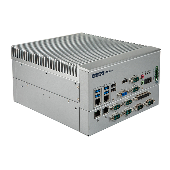
R sound channel amplifier switch OFF (default) I/O Connector HDMI USB2.0 AUDIO 9~36Vdc USB3.0+LAN COM1/2 POWER BUTTON 2 x LAN COM3~8 Expansion bracket(Op onal, such as LPT/PS2/DIO) 1x PCIe x 8 or 1 x PCI 1 x PCI ITA-3650E Series User Manual... -
Page 23: Com Connectors
2.4.1 COM Connectors ITA-3650E series provides up to eight D-sub 9-pin connectors for RS-232/422/485. RS-232 RS-422 RS-485 Signal Name Signal Name Signal Name DATA- DATA+ 2.4.2 USB Connector ITA-3650E provides serial USB3.0 and USB2.0 connector. They can be disabled in the system BIOS setup. -
Page 24: Vga Connector
H-SYNC V-SYNC DDC-CLK 2.4.4 DIO Connector ITA-3650E provides a DIO connector that needs cabling. Signal Name 1-12 Digital input (input) 14-25 Digital output (output) 2.4.5 Audio in Connector ITA-3650E provides an integrated Mic-in/speaker out audio connector. ITA-3650E Series User Manual... -
Page 25: Lan Connector
2.4.6 LAN Connector ITA-3650E series uses Intel I210 & IWGI219LM & Intel I211 Ethernet controllers, which are fully compliant with IEEE 802.3u 10/100/1000 Mbps standard. Signal Name Signal Name A1/B1 MDIO0+ MDIO0+ A2/B2 MDIO0- MDIO0- A3/B3 MDIO1+ MDIO1+ A4/B4 MDIO2+... -
Page 26: Lpt Connector
2.4.8 LPT Connector ITA-3650E-00A1 provides an LPT connector, which could connect a printer through cables. Signal Name Signal Name LPT_z_STB# LPT_AFD# LPT_z_PD0 LPT_ERR# LPT_PD1 LPT_INIT# LPT_PD2 LPT_SLIN# LPT_PD3 LPT_PD4 LPT_PD5 LPT_PD6 LPT_PD7 LPT_ACK# LPT_BUSY LPT_PE LPT_SLCT ITA-3650E Series User Manual... -
Page 27: Chapter 3 System Setup
Chapter System Setup This chapter introduces the instal- lation process of ITA-3650E. -
Page 28: Introduction
The following procedures will instruct you how to install all modules into the ITA- 3650E system. 3.1.1 Installing the Motherboard mSATA Card ITA-3650E motherboard front panel includes an mSATA card slot for the user to insert an mSATA card directly. Figure 3.1 Installing the Motherboard mSATA Card ITA-3650E Series User Manual... -
Page 29: Installing The Mini Pcie Card
The ITA-3650E motherboard supports a Mini PCIe expansion card. Please refer to the installation procedure below. Insert a Mini PCIe card into motherboard PCIe slot. Lock and fix the Mini PCIe card via a copper pillar. Figure 3.2 Installing the Mini PCIe Card ITA-3650E Series User Manual... -
Page 30: Installing The Hdd Module
Connect the complete HDD module to the chassis and fix it with six screws. Stick the cooling pad onto the PCB panel of HDD. Align the cooling pad with the magnetic head to protect the head from being covered. Figure 3.3 Installing the HDD Module ITA-3650E Series User Manual... -
Page 31: Installing The Top Cover
Installing the Mounting Bracket Align the 2 mounting brackets with the screw holes on the chassis side panel, and secure them with the screws supplied. Top and bottom installation are both sup- ported. (See Fig 3.5) ITA-3650E Series User Manual... - Page 32 Figure 3.5 Installing the Mounting Bracket ITA-3650E Series User Manual...
-
Page 33: Installing Expansion Module
Please follow the below steps to install a CF card module. Loosen the eight screws in the I/O expansion module. Install the I/O expansion module on the base chassis according to Figure 3.6. Figure 3.6 Installing an expansion Module ITA-3650E Series User Manual... - Page 34 ITA-3650E Series User Manual...
-
Page 35: Chapter 4 Ami Bios
Chapter AMI BIOS This chapter introduces how to configure AMI BIOS. -
Page 36: Introduction
Introduction This chapter introduces how to configure the BIOS for ITA-3650E series.With the AMIBIOS Setup program, you can modify BIOS settings and control the special fea- tures of your computer. The Setup program uses a number of menus for making changes and turning the special features on or off. -
Page 37: Entering Setup
Entering Setup Turn on the computer to enter POST screen. When the BIOS information is shown press <DEL> and you will immediately be allowed to enter Setup. Figure 4.2 Press <DEL> to Enter Setup ITA-3650E Series User Manual... -
Page 38: Main Setup
System Date using the <Arrow> keys. Enter new values through the keyboard. Press the <Tab> key or the <Arrow> keys to move between fields. The date must be entered in MM/DD/YY format. The time must be entered in HH:MM:SS format. ITA-3650E Series User Manual... -
Page 39: Advanced Bios Features Setup
This page displays the information of the system's CPU. Active Processor Cores Select the number of cores to enable them in each processor package. The default setting is [ALL] Hyper-Threading Enable/disable CPU hyper-threading function. The default setting is [Enabled]. ITA-3650E Series User Manual... - Page 40 This page shows the version, mode, type, SKU of ME firmware in BIOS. ME State Manageability Features State AMT BIOS Features AMT Configuration ME Unconfig on RTC Clear Firmware Update Configuration ITA-3650E Series User Manual...
- Page 41 This option configures serial port 1/2 base addresses and IRQ, as well as RS- 232/422/485 mode. Serial Port 3 ~ 6 only supports RS-232 Parallel Port Configuration This option configures parallel port base addresses and IRQ ITA-3650E Series User Manual...
- Page 42 The user can read the temperature or voltage to analyse the status of the system. Case Open Warning 4.2.2.7 F81216SEC Super IO Configuration Serial Port 1/2/3/4 Configuration Serial Port 1 ~ 4 RS-232/422/485 mode configurations are decided by jumper setting for IO board. ITA-3650E Series User Manual...
- Page 43 The settings specify how the host computer and the remote computer will exchange data. Both computers should have the same or compatible set- tings. Console Redirection This sub-page shows the legacy serial port number. ITA-3650E Series User Manual...
- Page 44 Enable/disable I/O port 60h/64h emulation support. This should be enabled for complete USB keyboard legacy support for non-USB aware OS. USB transfer time-out Sets the time-out value for control, bulk, and interrupt transfers. 4.2.2.11 Network Stack Configuration ITA-3650E Series User Manual...
- Page 45 This option controls legacy/UEFI ROMs priority. Network Control the execution of UEFI and legacy PXE OpRom. Storage Control the execution of UEFI and legacy Storage OpRom. Video Control the execution of UEFI and legacy Video OpRom. ITA-3650E Series User Manual...
-
Page 46: Advanced Chipset Settings
Other PCE devices Determines OpRom execution policy for devices other than network, storage or video. 4.2.3 Advanced Chipset Settings System Agent (SA) Configuration PCH-IO Configuration 4.2.3.1 System Agent (SA) Configuration Memory Configuration Graphics Configuration ITA-3650E Series User Manual... -
Page 47: Security Setup
To access the sub menu for the following items, select the item and press <Enter> Change Administrator Password Change User Password ITA-3650E Series User Manual... -
Page 48: Boot Setup
This item allows BIOS to skip some testing steps of the boot process, so as to reduce system boot time. Default setting is "Disabled". Bootup NumLock State Enable or disable num-lock 4.2.6 Save and Exit Save Changes and Exit Save settings and exit. ITA-3650E Series User Manual... - Page 49 Discard changes that have been made. Restore Defaults Restore default settings. Save as User Defaults Save as user default settings. Restore as User Defaults Restore as user default settings. UEFI Built-in EFI Shell Enter built-in EFI shell. ITA-3650E Series User Manual...
- Page 50 ITA-3650E Series User Manual...
-
Page 51: Chapter 5 Driver Installation
Chapter Driver Installation This chapter describes how to Install drivers. -
Page 52: Introduction
Introduction Advantech offers a complete range of Device Driver and software support for Win- dows programming developers. You can apply the Windows Device Drivers to the most popular Windows Programming tools, such as Visual C++, Visual Basic, Bor- land C++ Builder and Borland Delphi. -
Page 53: Platform Windows Driver Setup
5.2.1 Platform Windows Driver Setup You can select the driver folder according to the installation processor platform. Navi- gate to the "6th-sky lake" folder or "7th-callback" folder ITA-3650E Series User Manual... - Page 54 ITA-3650E Series User Manual...
-
Page 55: Chapter 6 Gpio Programming Guide
Chapter GPIO Programming Guide This chapter introduces GPIO pro- gramming guide. -
Page 56: Ita-3650E Digital Dio Definition
Read GPI 9 Input Value: unsigned char data; data = inportb(0xC14); //first read corresponding IO Space register value if (data & 0x01); //00000001B, judge value of bit 0 High // 1 = High else // 0 = Low ITA-3650E Series User Manual... - Page 57 “Enter” to configure. Modify 90h,91h and 92h registers under the 256 byte table in ISA con- figuration page. Modified value: 01h in 90h, 0ch in 91h, and 1Ch in 92h. Ready for IO operation of GPIO. ITA-3650E Series User Manual...
- Page 58 ITA-3650E Series User Manual...
-
Page 59: Appendix A Programming The Watchdog Timer
Appendix Programming the Watchdog Timer... -
Page 60: Watchdog Timer Overview
The ITA-3650's watchdog timer can be used to monitor system software operation and take corrective action if the software fails to function within the programmed period. This section describes the operation of the watchdog timer and how to pro- gram it. Watchdog Timer Overview The watchdog timer is built into the super I/O controller NCT6116D. -
Page 61: Program Examples
;----------------------------------------------------------- Generate a time-out signal without timer counting ;----------------------------------------------------------- Mov dx,A68h ; Select register 68h, watchdog timer I/O port address A00h+ register shifts 68h In al,dx Or al,4h ; Generate a time-out signal Out dx,al ;----------------------------------------------------------- ITA-3650E Series User Manual... - Page 62 No part of this publication may be reproduced in any form or by any means, electronic, photocopying, recording or otherwise, without prior written permis- sion of the publisher. All brand and product names are trademarks or registered trademarks of their respective companies. © Advantech Co., Ltd. 2020...
- Page 63 用户手册 ITA-3650E 系列 无风扇嵌入式 高性能紧凑型工业电脑...
- Page 64 版权声明 随附本产品发行的文件为研华公司 2020 年版权所有,并保留相关权利。针对本手册中 相关产品的说明,研华公司保留随时变更的权利,恕不另行通知。未经研华公司书面 许可,本手册所有内容不得通过任何途径以任何形式复制、翻印、翻译或者传输。本 手册以提供正确、可靠的信息为出发点。但是研华公司对于本手册的使用结果,或者 因使用本手册而导致其它协力厂商的权益受损,概不负责。 认可声明 ITA-3650E 为研华公司的商标。 所有其他产品名或商标均为各自所属方的财产。 在线技术支持 关于技术支持和服务,请访问研华技术支持网站: http://support.advantech.com.cn 产品质量保证 (两年) 从购买之日起,研华为原购买商提供两年的产品质量保证。但对那些未经授权的维修 人员维修过的产品并不进行质量保证。研华对于不正确的使用、灾难、错误安装产生 的问题有免责权利。 如果研华产品出现故障,在质保期内我们提供免费维修或更换服务。对于出保产品, 我们将会酌情收取材料费、人工服务费用。请联系您的销售人员了解详细情况。 如果您认为您购买的产品出现了故障,请遵循以下步骤: 收集您所遇到的问题的信息 (例如,CPU 主频、使用的研华产品及其它软件、硬 件等) 。请注意屏幕上出现的任何不正常信息显示。 打电话给您的供货商,描述故障问题。请借助手册,产品和任何有帮助的信息。 如果您的产品被诊断发生故障,请从您的供货商那里获得 RMA (Return Material Authorization) 序列号。这可以让我们尽快地进行故障产品的回收。 请仔细地包装故障产品,并在包装中附上完整的售后服务卡片和购买日期证明 (如销售发票) 。我们对无法提供购买日期证明的产品不提供质量保证服务。 把相关的 RMA 序列号写在外包装上,并将其运送给销售人员。...
- Page 65 致客户 研华为客户提供的服务 研华的每一款产品都是严格按照规格生产的。这样,产品的可靠性在恶劣粗糙的工业 环境下也可以得到保证。无论您购买的研华产品属于实验室还是工厂层,请坚信研华 产品都将一如既往地保持高度的可靠性和易于操作性。客户的满意是我们最关注的。 下面是研华客户服务指南。为保证您从我们的服务中获得最大的利益,请谨慎遵循下 面的操作指南。 技术支持 我们衷心希望您购买的产品能够发挥最大的性能。如果您遇到技术问题,我们随时准 备为您提供帮助。对于常见问题,您可以在产品文档中找到满意答案。这些答案通常 比我们可以在电话上给您提供的答案更为详细。 请先参考本手册。如果仍找不到方案,请搜集和故障有关的所有信息和问题,汇同你 手边的资料,给您的经销商打电话。我们的经销商都是接受过专业培训的。通过您提 供的产品信息,他们会为您提供所需要的技术支持。事实上,多数问题都是很微小的, 通过电话咨询即可解决。 此外,在每个工作日,研华工程师都为客户提供免费的技术支持。关于研华任意一款 产品安装和操作方面的应用需求或具体信息,我们都时刻准备着为您提供相关的建 议。 初始检查 打开包装时,用户需确认包装中含有下面所列各项: 1 x ITA-3650E 系列工业电脑 1 x ITA-3650E 附件盒 1 x 质保卡 如果其中任何一项缺失或者破损,请立即联系您的销售商或销售代表。装货前,我们 已全面仔细检查过 ITA-3650E 产品。 因此您购买的产品应当是完好无损且运转正常的。 在您打开 ITA-3650E 产品的包装时,请检查是否有破损痕迹 (例如,包装箱损坏、划 痕、凹痕等)...
- Page 66 RoHS Claim 設備名稱:電腦 型號 (型式) :ITA-3650 (型號參見說明書) Equipment name Type designation (Type) 限用物質及其化學符號 Restricted substances and its chemical symbols 多溴聯苯 六價鉻 多溴二苯醚 單元 Unit 鎘 Polybromina Hexavalent 鉛 Lead 汞 Mercury Polybrominate Cadmium chromium d diphenyl (Pb) (Hg) (Cd) biphenyls ethers (PBDE) (PBB) 電路板...
- Page 67 安全指示 请仔细阅读此安全操作说明。 请妥善保存此用户手册供日后参考。 用湿抹布清洗设备前,请从插座拔下电源线。请不要使用液体或去污喷雾剂清洗 设备。 对于使用电源线的设备,设备周围必须有容易接触到的电源插座。 请不要在潮湿环境中使用设备。 请在安装前确保设备放置在可靠的平面上,意外跌落可能会导致设备损坏。 当您连接设备到电源插座上前,请确认电源插座的电压是否符合要求。 请将电源线布置在人们不易绊到的位置,并不要在电源线上覆盖任何杂物。 请注意设备上的所有警告和注意标语。 如果长时间不使用设备,请将其同电源插座断开,避免设备被超标的电压波动损 坏。 请不要让任何液体流入机体内部,以免引起火灾或者短路 请不要自行打开设备。为了确保您的安全,请由经过认证的工程师来打开设备。 如遇下列情况,请由专业人员来维修: 电源线或者插头损坏; 设备内部有液体流入; 设备曾暴露在过于潮湿的环境中使用; 设备无法正常工作,或您无法通过用户手册来使其正常工作; 设备跌落或者损坏; 设备有明显的外观破损。 请不要把设备放置在超出我们建议的温度范围的环境,即不要低于 -25°C (- 13°F)或高于 60°C (140°F) ,否则可能会损坏设备。 此为 A 级产品,在生活环境中,该产品可能会造成无线电干扰。在这种情况下, 可能需要用户对干扰采取切实可行的措施。 本产品不带电线组件销售,应购买已通过 CCC 认证的电线组件。 注意:计算机配置了由电池供电的实时时钟电路,如果电池更换不正确,将有爆 炸的危险。因此,只可以使用制造商推荐的同一种或者同等型号的电池进行替 换。请按照制造商的指示处理旧电池。 根据 IEC 704-1:1982 的规定,操作员所在位置的声压级不可高于 70dB(A)。 免责声明:该安全指示符合...
- Page 68 ITA-3650E 系列用户手册...
- Page 69 目录 第 1 章 概述 ........1 产品简介............2 产品规格............2 电源信息............2 表 1.1: 电源...........2 环境规格............2 表 1.2: 环境规格........2 产品尺寸............3 图 1.1: ITA-3650E 产品尺寸 ......4 分解图............5 图 1.2: ITA-3650E 分解图 .......5 表 1.3: 零件列表........5 第 2 章 硬件安装 ....... 7 简介............8 系统状态指示灯..........8 2.2.1 系统状态...
- Page 70 图 3.5: 安装脚架 ........26 3.1.6 安装 I/O 扩展模组........27 图 3.6: 安装、模组 CF 卡 ......27 第 4 章 AMI BIOS 设置......29 简介 ............30 图 4.1: 设置程序初始页面 ......30 进入设置界面 ..........31 图 4.2: 按 <DEL> 键进入设置界面 ....... 31 4.2.1 主设置界面...
- Page 71 第 1 章 概述 本章介绍了 ITA-3650E 的基本信息。...
-
Page 72: 产品简介
产品简介 ITA-3650E 是一款支持 Intel® 第六代和第七代高性能处理器,及宽电压输入的无风扇 嵌入式紧凑型工业电脑,是研华公司为智能交通 - 高速公路、监控和 ETC 不停车收费 领域推出的专用机型。这款功能强大的计算平台能够 7 天 24 小时连续工作。 产品规格 芯片和芯片组:Intel® 第六代和第七代桌面处理器 BIOS:AMI SPI 64 Mb Flash 内存:板载 8G,最大可以支持 32G 显示:Intel® HD Graphics 630/610/530/510z 双显模式:单显分辨率可达 3840 x 2160@ 30Hz 双显分辨率可达... -
Page 73: 产品尺寸
产品尺寸 [9.449] [7.480] [4.843] [6.693] [4.803] [5.906] 图 1.1: ITA-3650E 产品尺寸 ITA-3650E 系列用户手册... -
Page 74: 分解图
分解图 图 1.2: ITA-3650E 分解图 表 1.3:零件列表 散热片 电源板 机箱 -U HDD 模块 I/O 保护盖 扩展模块 母板 ITA-3650E 系列用户手册... - Page 75 第 2 章 硬件安装 本章介绍了 ITA-3650E 的硬件安装。...
-
Page 76: 系统状态指示灯
简介 以下章节介绍了内部跳线设置和外部接口针脚分配信息,用于实现应用集成。 系统状态指示灯 2.2.1 系统状态 LED 指示灯 前面板右上侧 LED 用于指示系统健康和活跃状态。 HDD Indicator Power/Alarm Indicator 图 2.1: ITA-3650E LED LED 定义的详细信息请参考下表。 项目 状态 色彩 描述 亮起 绿色 系统电源接通,系统安全 电源 / 故障 亮起 红色 系统温度过高 亮起 黄色 数据正在接收 / 传输 硬盘 熄灭 没有数据正在接收... -
Page 77: 跳线和接口
跳线和接口 2.3.1 跳线描述 用户可根据需要通过设置跳线配置 ITA-3650E。跳线是用来连通电路的金属桥。它包括 2 个金属针脚和一个跳线帽(里面是金属夹片,外部是起保护作用的塑料套) 。跳线帽 可套住针脚将其连成通路。移走跳线帽则会断开线路。有时,一个跳线具有 3 个针脚, 分别为针 1、2、3。这种情况下,用户可以任意选择连接针脚 1、2 或者针脚 2、3。 断开 闭合 闭合 2-3 设备的跳线设置如下图所示: 闭合 2-3 断开 闭合 断开 闭合 闭合 2-3 进行跳线设置时,使用针鼻钳可能会有所帮助。若用户对应用的最佳硬件配置产生任 何疑问,请在进行更改前联系当地的分销商或销售代表。通常情况下,用户仅需要一 根标准电缆进行大多数连接。 ITA-3650E 系列用户手册... -
Page 78: 跳线和接口位置
2.3.2 跳线和接口位置 板卡带有一些接口和跳线,可供用户根据应用需要进行系统配置。每个接口和跳线的 功能如下表所示。跳线和接口在电路板的位置可参照图 2.3 和图 2.4 所示。 表 2.1:跳线和接口 名称 功能 JCMOS1 清除 CMOS 设置 AMPL1 L 声道放大器开关 AMPR1 R 声道放大器开关 PSON1 AT/ATX 模式选择 VCCGPIO1 GPIO 电压设定 SATA1 SATA 数据接口 1 SATA2 SATA 数据接口 2 SATA3 SATA 数据接口 3 SATA_PWR1 SATA 电源接口... -
Page 79: 图 2.3: 扩展 I/O 板接口及跳线位置图
JSETCOM7 COM9_10 JSETCOM8 COM7_8 JSETCOM10 JSETCOM9 GPIO2 JSETCOM5 JSETCOM6 JSETCOM3 JSETCOM4 图 2.3: 扩展 I/O 板接口及跳线位置图 PWR1 PWR3 表 2.2:JLVDS1: LVDS 电压设定 闭合针脚 设置 +12V +3.3V (默认) +12V +3.3V 表 2.3:JCOMS1:Clear COMS 设定 闭合针脚 设置 正常 (+V3.3_SB)* 清除 CMOS 设定 * 默认设置... -
Page 80: 表 2.4:Vccgpio1:Gpio 电压设定
表 2.4:VCCGPIO1:GPIO 电压设定 闭合针脚 设置 +V3.3_SB +V5_SB (默认) +V3.3 +V5_SB +V3.3_SB 表 2.5:PSON1:开机模式设定 闭合针脚 设置 AT 模式 ATX 模式 * * 默认设置 AT 模式 ATX 模式 表 2.6:AMPL1:L 声道放大器开关 闭合针脚 设置 1-2,4-5 L 声道放大器打开 (默认) 2-3,5-6 L 声道放大器关闭 表 2.7:AMPR1:R 声道放大器开关 闭合针脚... -
Page 81: I/O 接口
I/O 接口 USB2.0 HDMI AUDIO 9~36Vdc USB3.0+LAN COM1/2 POWER BUTTON 2 x LAN COM3~8 Expansion bracket(Op onal, such as LPT/PS2/DIO) 1x PCIe x 8 or 1 x PCI 1 x PCI 2.4.1 COM 端口 ITA-3650E 提供了 8 个 D-sub 9 针 RS-232/RS-422/RS-485 接口。 RS-232 RS-422 RS-485... -
Page 82: Usb 接口
2.4.2 USB 接口 ITA-3650E 提供一系列 USB3.0 和 USB2.0 接口。可以通过 Bios 来禁用。 针脚 信号名 +V5(VCC) USB_data- USB_data+ 2.4.3 VGA 接口 ITA-3650E 提供 1 个 D-SUB 15 针的母型接口。 针脚 信号名 Red( 红 ) Green( 绿 ) Blue( 蓝 ) DDC-DATA H-SYNC V-SYNC DDC-CLK ITA-3650E 系列用户手册... -
Page 83: Dio 接口
2.4.4 DIO 接口 ITA-3650E 提供一个 DIO 接口,需要通过线缆连接。 针脚 信号名 1-12 数字输入 (input) 14-25 数字输出 (output) 2.4.5 Audio in 接口 ITA-3650E 提供一个集成麦克风输入 / 扬声器输出的音频接口。 2.4.6 LAN 端口 ITA-3650E 系列带有 Intel I210 & I211 & IWGI219LM 以太网控制器,完全符合 IEEE 802.3u 10/100/1000 Mbps 标准。 针脚... -
Page 84: Phoenix 端子接口
2.4.7 Phoenix 端子接口 ITA-3650E 提供一个 4pin 的凤凰端子的电源输入连接器。 针脚 信号名 正极 2.4.8 LPT 接口 ITA-3650E 提供一个 LPT 接口,可以通过线缆连接显示器。 针脚 信号名 针脚 信号名 LPT_z_STB# LPT_AFD# LPT_z_PD0 LPT_ERR# LPT_PD1 LPT_INIT# LPT_PD2 LPT_SLIN# LPT_PD3 LPT_PD4 LPT_PD5 LPT_PD6 LPT_PD7 LPT_ACK# LPT_BUSY LPT_PE LPT_SLCT ITA-3650E 系列用户手册... - Page 85 第 3 章 系统安装 本章介绍了 ITA-3650E 的安装过程。...
-
Page 86: 安装主板 M-Sata 卡
简介 以下步骤将指导用户组装 ITA-3650E 中的各个模块。 3.1.1 安装主板 M-SATA 卡 ITA-3650E 主板端前部有一 M-SATA 卡槽,将 M-SATA 卡直接装入即可。 图 3.1: 安装主板 M-SATA 卡 ITA-3650E 系列用户手册... -
Page 87: 安装 Mini Pcie
3.1.2 安装 Mini PCIe ITA-3650E 主板可以扩展出一个 Mini PCIe 卡,安装时请按照下面步骤: 将一个 Mini PCIe 卡插入主板 PCIe 插槽。 用铜柱及螺丝将 Mini PCIe 卡锁住固定。 图 3.2: 安装 Mini PCIe 卡 ITA-3650E 系列用户手册... - Page 88 3.1.3 安装硬盘模块 ITA-3650E 预留有一个可以安装 2.5” 硬盘模块的空间。请参考以下指导安装: 将硬盘放入 2.5” 硬盘固定架,并用 4 颗螺丝锁好。 硬盘固定架开有 7 个半圆孔,在半圆孔中装入橡胶垫。 将硬盘固定架架套在硬盘支架上,用 7 颗螺丝锁好。 将整个组装好的硬盘模组接入机箱并用 6 颗螺丝固定。 在硬盘的 PCB 面板上贴上散热泥,散热泥圆孔对准磁头,以防磁头被散热泥压 住。 图 3.3: 安装硬盘模块 ITA-3650E 系列用户手册...
-
Page 89: 安装上盖
3.1.4 安装上盖 请按照下面步骤安装机箱顶盖。 按照图 3.4 上盖所示的方向将切口端插入机箱前面板处,然后压好。 用 4 颗螺丝将机箱顶盖固定。 图 3.4: 安装上盖 3.1.5 安装脚架 将 2 个脚架与机箱侧壁处的螺丝孔对好,用螺丝锁好即可。可选顶面或底面安装。 (如 图 3.5) ITA-3650E 系列用户手册... - Page 90 图 3.5: 安装脚架 ITA-3650E 系列用户手册...
- Page 91 3.1.6 安装 I/O 扩展模块 请按照下面步骤安装 I/O 扩展模块。 将 I/O 扩展模组周边 8 颗螺丝拆下,并往上拔出模块。 按照图 3.6 所示方向将 I/O 扩展模块安装回底座,再将螺丝拧紧。 图 3.6: 安装 IO 模块 ITA-3650E 系列用户手册...
- Page 92 ITA-3650E 系列用户手册...
-
Page 93: Ami Bios 设置
第 4 章 AMI BIOS 设置 本章介绍如何配置 AMI BIOS。... - Page 94 简介 AMI BIOS 已被集成到多种工业级和嵌入式母板中,在近年来非常受欢迎。本章介绍如 何配置 BIOS,使之适用于 ITA-3650E 系列产品。用户可在 AMI BIOS 设置实用程序中更 改 BIOS 设置、实现对 ITA-3650E 系列特殊性能的控制。设置程序内包含多个菜单,允 许用户对计算机性能进行设置。本章介绍 ITA-3650E 系列 BIOS 设置的基本知识。 图 4.1: 设置程序初始页面 BIOS ROM 带有内置的设置程序,允许用户修改基本系统配置信息。这些信息保存在由 电池供电的 CMOS 中,因此在电源关闭时仍不会丢失。 ITA-3650E 系列用户手册...
-
Page 95: 进入设置界面
进入设置界面 开启计算机后,屏幕上将出现 POST ( 上电自检 ) ,显示 BIOS 和 CPU 信息。按 <Del> 键即可进入 BIOS 设置界面。 图 4.2: 按 <DEL> 键进入设置界面 ITA-3650E 系列用户手册... -
Page 96: 主设置界面
4.2.1 主设置界面 首次进入设置实用程序时,即会进入主设置页面。点击 "Main" 标签即可随时返回主菜 单。本节共介绍共有 2 个主设置选项。BIOS 主设置页面如下图所示: 图 4.3: 主设置界面 BIOS 设置主菜单由 2 部分构成。左栏显示的是可以配置的所有项。灰色的为不可配置 的项,蓝色的则相反。右边栏为箭头图例。箭头上方的空白区域是为文字信息预留的。 如果在左边栏选择了某项,该项将以加亮白色字体显示, 且在预留的文字信息处显示 简介文字。 System Time/System Date 此项可用于改变系统时间和日期。用户可使用方向键选中系统时间或系统日期, 并可通过键盘输入新值。按 Tab 键或方向键可在各项间进行切换。日期的格式为 MM/DD/YY, 时间的格式为 HH:MM:SS。 ITA-3650E 系列用户手册... -
Page 97: 高级 Bios 特性设置
4.2.2 高级 BIOS 特性设置 从 ITA-3650E 系列的设置界面点击 “Advanced” 标签即可进入高级 BIOS 设置界面。 用 户可选择左边边框中的项进入相应项的子菜单,如 CPU Configuration。用户可使用方 向键来选中相应的设置项。所有的高级 BIOS 设置选项都在此节中进行描述,如下图所 示。子菜单将在后面进行介绍。 图 4.4: 高级 BIOS 特性设置 4.2.2.1 CPU Configuration 该页显示系统 CPU 信息。 Active Processor Cores 选择每个处理器包中启用的内核的数量。默认设置为 [ALL]。 Hyper-Threading 启用 / 禁用 CPU 超线程技术。默认设置为 [Enabled]。 ITA-3650E 系列用户手册... - Page 98 4.2.2.2 Power & Performance CPU-Power Management Control 4.2.2.3 PCH-FW Configuration 该页显示内置于 BIOS 中的 ME 固件的版本、模式、类型和 SKU。 ME State Manageability Features State AMT BIOS Features AMT Configuration ME Unconfig on RTC Clear Firmware Update Configuration ITA-3650E 系列用户手册...
- Page 99 4.2.2.4 ACPI Setting Enable Hibernation ACPI Sleep State 4.2.2.5 NCT6116D Supper IO Configuration Serial Port 1/2/3/4/5/6 Configuration 配置串口 1/2 基础地址、IRQ 和 RS-232/422/485 模式。串口 3 ~ 6 仅支持 RS-232 Parallel Port Configuration 配置并行端口基础地址和 IRQ ITA-3650E 系列用户手册...
- Page 100 4.2.2.6 NCT6116D HW Monitor 该页显示硬件显示器可访问的部分硬件信息。用户可通过温度或电压读数来分析系统 状态。 Case Open Warning 4.2.2.7 F81216SEC Super IO Configuration Serial Port 1/2/3/4 Configuration 串口 1 ~ 4 RS-232/422/485 模式配置取决于 IO 板卡跳线设置。 ITA-3650E 系列用户手册...
- Page 101 4.2.2.8 F81216TRD Super IO Configuration Serial Port 1/2/3/4 Configuration 串口 1 ~ 4 RS-232/422/485 模式配置取决于 IO 板卡跳线设置。 4.2.2.9 Serial Port Console Redirection 该页显示控制台状态。用户可在 [Console redirection Settings] 中配置控制台设 置。 Console Redirection Settings 启用 / 禁用控制台重定向功能。默认设置为 [disabled]。 Legacy Console Redirection Settings 控制台重定向功能启用后无法进入此...
- Page 102 4.2.2.10USB Configuration Legacy USB Support 启用 / 禁用传统 USB 支持。默认设置为 [enabled]。 XHCI Hand-off 此项是为无 XHCI hand-off 支持的操作系统系统的替代方法。XHCI 拥有者变更 需要由 XHCI 驱动声明。 USB Mass Storage 启用 / 禁用 USB 大容量存储驱动支持。 Driver Support Port 60/64 Emulation 启用 / 禁用 I/O 端口 60h/64h 仿真支持。对于不能识别 USB 的操作系统,应启 用此项,以获得完整的...
- Page 103 Network Stack 启用 / 禁用 UEFI 网络堆栈。默认值为 [Disabled]。启用网络堆栈后,将显示 以下图片: Ipv4 PXE Support 启用 / 禁用 IPV4 PXE 支持。禁用后,将不会创建 IPV4 PXE 启动选项。 Ipv4 HTTP Support Ipv6 PXE Support 启用 / 禁用 IPV6 PXE 支持。禁用后,将不会创建 IPV6 PXE 启动选项。 ...
-
Page 104: 高级芯片组设置
Other PCE devices 决定网络、存储或视频之外的其它设备的 OpROM 执行策略。 4.2.3 高级芯片组设置 System Agent (SA) Configuration PCH-IO Configuration 4.2.3.1 System Agent (SA) Configuration Memory Configuration Graphics Configuration ITA-3650E 系列用户手册... -
Page 105: 安全设置
4.2.3.2 PCH-IO Configuration SATA And RST Configuration PCH LAN Controller Wake on LAN Enable Serial IRQ Mode State After G3 4.2.4 安全设置 从 ITA-3650E 系列的 BIOS 设置主菜单内选择 ”Security” 标签即可进入安全设 置。所有的安全设置选项,如密码保护和病毒保护都将在本节中进行描述。用户可按 <Enter> 键进入每项的子菜单。 Change Administrator Password ... -
Page 106: 启动设置
4.2.5 启动设置 Setup Prompt Timeout 默认为 “1s”。 用于设置 Setup 提示等待时间。 Quiet Boot 如果设置为 “Disabled”,则 BIOS 将显示正常的 POST 信息。如果设置为 “Enabled” 屏幕上将出现 OEM 图标,而非 POST 信息。 Fast Boot 此项允许 BIOS 在启动过程中跳过一些检测步骤,从而减少系统启动的时间。默 认设置为 “Disabled”。 Bootup NumLock State 选择数字键盘锁是否开启。 4.2.6 保存并退出... - Page 107 Discard Changes and Exit 不保存设置并退出。 Save Changes and Reset 保存设置并重启。 Discard Changes and Reset 不保存设置并重启。 Save Changes 保存目前已变更的设置。 Discard Changes 不保存目前已变更的设置。 Restore Defaults 恢复默认设置。 Save as User Defaults 保存为用户默认设置。 Restore as User Defaults 恢复为客户默认设置。...
- Page 108 ITA-3650E 系列用户手册...
- Page 109 第 5 章 驱动安装 本章介绍了如何进行驱动安装。...
-
Page 110: 驱动安装
简介 研华为 Windows 程序开发人员提供了完整的设备驱动和软件。该设备驱动可应用于最 通用的 Windows 编程工具中,如 Visual C++, Visual Basic, Borland C++ Builder and Borland Delphi。 驱动安装 用户可以从研华官网下载 ITA-3650E 驱动, 用户即可看到 ITA-3650E 系列驱动文件夹。 ITA-3650E 系列用户手册... -
Page 111: 不同 Cpu Windows 驱动安装
5.2.1 不同 CPU Windows 驱动安装 用户根据安装的第六代或者第七代处理进行选择驱动文件夹来完成驱动安装。 ITA-3650E 系列用户手册... - Page 112 ITA-3650E 系列用户手册...
-
Page 113: Gpio 编程指南
第 6 章 GPIO 编程指南 本章介绍了 GPIO 编程指南。... -
Page 114: Ita-3650E 数字 Dio 定义 (见 2.4.8
ITA-3650E 数字 DIO 定义 (见 2.4.8) 配置顺序 ITA-3650E 上板上走 LPC 总线的 GPIO 通过 Lattice CPLD 实现。 对此 CPLD GPIO IC 的设置和访问需要通过访问系统的 IO Space 来完成。 GPIO IO Space 和对应 GPIO 引脚的映射: Port GPO : IO 0xC10~0xC12 (bit0-bit23) 0xC10:bit0~bit7 GPO(1~8) 0xC11:bit0~bit7 GPO(9~16) 0xC12:bit0~bit7 GPO(17~24) Port GPI : IO 0xC13~0xC15 (bit0-bit23) 0xC13:bit0~bit7 GPI(1~8) - Page 115 注! 请检查当前使用的 BIOS 版本,若当前版本是 X006 版本或者更早。那么 手动打开 IO decode,打开方法如下: 在 DOS 下使用 Adu.exe 或者 XP 下 RW。以下假设一切操作都在 DOS 下。 运行 Adu,选择 PCI 菜单,找到 ISA Bridge 这一行,并回车进入配置。 在 ISA 配置页面的 256 个字节的 table 中,修改 90h,91h,92h 三个寄存 器。 对应修改:90h 填 01h,91h 填 0ch,92h 填 1Ch。 可以开始对...
- Page 116 ITA-3650E 系列用户手册...
-
Page 117: 附录 A
附录 A 看门狗定时器编程... -
Page 118: 看门狗定时器概述
ITA-3650E 看门狗定时器可用于监控系统软件操作, 并在编程过程中出现软件故障时采 取适当措施。本章节介绍了看门狗定时器操作以及如何编程。 看门狗定时器概述 看门狗定时器内置于高级 I/O 控制器 NCT6116D,提供了以下用户可编程功能: 可通过用户编程启用或禁用; 定时器可设置为 1 ~ 255 秒或 1 ~ 255 分钟; 在软件复位定时器超时时产生中断或复位信号。 编程看门狗定时器 看门狗定时器的 I/O 端口地址为 A00h (hex) 。 表 A.1:看门狗定时器寄存器 地址:A00 (hex) 寄存器偏移 读 / 写 说明 将定时器计时单位设置为秒或分钟: 向... - Page 119 编程示例 启用看门狗定时器,并将超时间隔设置为 10 秒。 ;----------------------------------------------------------- Mov dx,A65h ; 选择寄存器 65h, 看门狗定时器的 I/O 端口地址 A00h+ 寄存器偏移 65h Mov al,80h ; 将计时单位设置为秒 Out dx,al Mov dx,A66h ; 选择寄存器 66h, 看门狗定时器的 I/O 端口地址 A00h+ 寄存器偏移 66h Mov al,10 ; 将超时间隔设置为 10 秒然后开始计时 Out dx,al ;----------------------------------------------------------- 启用看门狗定时器功能并将超时间隔设置为...
- Page 120 使用前请检查核实产品的规格。本手册仅作为参考。 产品规格如有变更,恕不另行通知。 未经研华公司书面许可,本手册中的所有内容不得通过任何途径以任何形式复制、翻 印、翻译或者传输。 所有其他产品名或商标均为各自所属方的财产。 © 研华公司 2020...
- Page 121 用戶手冊 ITA-3650E 系列 無風扇嵌入式 高性能緊湊型工業電腦...
- Page 122 版權聲明 隨附本產品發行的檔為研華公司 2020 年版權所有,並保留相關權利。針對本手冊中相 關產品的說明,研華公司保留隨時變更的權利,恕不另行通知。未經研華公司書面許 可,本手冊所有內容不得通過任何途徑以任何形式複製、翻印、翻譯或者傳輸。本手 冊以提供正確、可靠的資訊為出發點。但是研華公司對於本手冊的使用結果,或者因 使用本手冊而導致其它協力廠商的權益受損,概不負責。 認可聲明 ITA-3650E 為研華公司的商標。 所有其他產品名或商標均為各自所屬方的財產。 線上技術支援 關於技術支援和服務,請訪問研華技術支援網站: http://support.advantech.com.tw 產品保固 (兩年) 從購買之日起,研華為原購買商提供兩年的產品品質保證。但對那些未經授權的維修 人員維修過的產品不予提供品質保證。研華對於不正確的使用、災難、錯誤安裝產生 的問題有免責權利。 如果研華產品出現故障,在質保期內我們提供免費維修或更換服務。對於出保產品, 我們將會酌情收取材料費、人工服務費用。請聯繫相關銷售人員瞭解詳細情況。 如果您認為您購買的產品出現了故障,請遵循以下步驟: 收集您所遇到的問題資訊 (例如,CPU 主頻、使用的研華產品及其它軟體、硬 體 等) 。請注意螢幕上出現的任何不正常資訊顯示。 打電話給您的供應商,描述故障問題。請借助手冊、產品和任何有説明的資訊。 如果您的產品被診斷發生故障,請從您的供應商那裡獲得 RMA (Return Material Authorization) 序號。這可以讓我們儘快地進行故障產品的回收。 請仔細地包裝故障產品,並在包裝中附上完整的售後服務卡片和購買日期證明 (如銷售發票) 。我們對無法提供購買日期證明的產品不提供品質保證服務。 把相關的 RMA 序號寫在外包裝上,並將其運送給銷售人員。...
- Page 123 致客戶 研華為客戶提供的服務 研華的每一款產品都是嚴格按照規格生產的。這樣,產品的可靠性在惡劣粗糙的工業 環境下也可以得到保證。無論您購買的研華產品屬於實驗室還是工廠層,請堅信研華 產品都將一如既往地保持高度的可靠性和易於操作性。客戶的滿意是我們最關注的。 下面是研華客戶服務指南。為保證您從我們的服務中獲得最大的利益,請謹慎遵循下 面的操作指南。 技術支援 我們衷心希望您購買的產品能夠發揮最大的性能。如果您遇到技術問題,我們隨時准 備為您提供幫助。對於常見問題,您可以在產品文檔中找到滿意答案。這些答案通常 比我們可以在電話上給您提供的答案更為詳細。 請先參考本手冊。如果仍找不到方案,請搜集和故障有關的所有資訊和問題,匯同你 手邊的資料,給您的經銷商打電話。我們的經銷商都是接受過專業培訓的。通過您提 供的產品資訊,他們會為您提供所需要的技術支援。事實上,多數問題都是很微小的, 通過電話諮詢即可解決。 此外,在每個工作日,研華工程師都為客戶提供免費的技術支援。關於研華任意一款 產品安裝和操作方面的應用需求或具體資訊,我們都時刻準備著為您提供相關的建 議。 初始檢查 打開包裝時,用戶需確認包裝中含有下面所列各項: 1 x ITA-3650E 系列工業電腦 1 x ITA-3650E 附件盒 1 x 質保卡 如果其中任何一項缺失或者破損,請立即聯繫您的銷售商或銷售代表。裝貨前,我們 已全面仔細檢查過 ITA-3650E 產品。 因此您購買的產品應當是完好無損且運轉正常的。 在您打開 ITA-3650E 產品的包裝時,請檢查是否有破損痕跡 (例如,包裝箱損壞、劃 痕、凹痕等)...
- Page 124 RoHS Claim 設備名稱:電腦 型號 (型式) :ITA-3650 (型號參見說明書) Equipment name Type designation (Type) 限用物質及其化學符號 Restricted substances and its chemical symbols 多溴聯苯 六價鉻 多溴二苯醚 單元 Unit 鎘 Polybromina Hexavalent 鉛 Lead 汞 Mercury Polybrominate Cadmium chromium d diphenyl (Pb) (Hg) (Cd) biphenyls ethers (PBDE) (PBB) 電路板...
- Page 125 請仔細閱讀此安全操作說明。 請妥善保存此用戶手冊供日後參考。 用濕抹布清洗設備前,請從插座拔下電源線。請不要使用液體或去汙噴霧劑清洗 設備。 對於使用電源線的設備,設備周圍必須有容易接觸到的電源插座。 請不要在潮濕環境中使用設備。 請在安裝前確保設備放置在可靠的平面上,意外跌落可能會導致設備損壞。 設備外殼的開口是用於空氣對流,從而防止設備過熱。請不要覆蓋這些開口。 當您連接設備到電源插座上前,請確認電源插座的電壓是否符合要求。 請將電源線佈置在人們不易絆到的位置,並不要在電源線上覆蓋任何雜物。 請注意設備上的所有警告和注意標語。 如果長時間不使用設備,請將其同電源插座斷開,避免設備被超標的電壓波動損 壞。 請不要讓任何液體流入通風口,以免引起火災或者短路。 請不要自行打開設備。為了確保您的安全,請由經過認證的工程師來打開設備。 如遇下列情況,請由專業人員來維修: 電源線或者插頭損壞; 設備內部有液體流入; 設備曾暴露在過於潮濕的環境中使用; 設備無法正常工作,或您無法通過用戶手冊來使其正常工作; 設備跌落或者損壞; 設備有明顯的外觀破損。 請不要把設備放置在超出我們建議的溫度範圍的環境,即不要低於 -20°C (- 4°F)或高於 60°C (140°F) ,否則可能會損壞設備。 注意:電腦配置了由電池供電的即時時鐘電路,如果電池放置不正確,將有爆 炸的危險。因此,只可以使用製造商推薦的同一種或者同等型號的電池進行替 換。請按照製造商的指示處理舊電池。 根據 IEC 704-1:1982 的規定,操作員所在位置的聲壓級不可高於 70dB(A)。 免責聲明:該安全指示符合...
- Page 126 ITA-3650E 系列用戶手冊...
- Page 127 目录 第 1 章 概述 ........1 產品簡介............2 產品規格............2 電源資訊............2 表 1.1: 電源...........2 環境規格............2 表 1.2: 環境規格........2 產品尺寸............3 图 1.1: ITA-3650E 產品尺寸 ......4 分解圖............5 图 1.2: ITA-3650E 分解圖 .......5 表 1.3: 零件清單........5 第 2 章 硬體安裝 ....... 1 簡介............2 系統狀態指示燈..........2 2.2.1 系統狀態...
- Page 128 图 3.5: 安裝腳架 ........6 3.1.6 安裝 I/O 擴展模組........7 图 3.6: 安裝、模組 CF 卡 ....... 7 第 4 章 基本資訊 ....... 1 產品簡介 ............2 硬體規格 ............2 機械規格 ............3 4.3.1 產品尺寸 ..........3 4.3.2 重量 ............ 4 電源規格...
- Page 129 第 1 章 概述 本章介紹了 ITA-3650E 的基本資訊。...
-
Page 130: 產品簡介
產品簡介 ITA-3650E 是一款支援 Intel® 第六代和第七代高性能處理器,及寬電壓輸入的無風扇 嵌入式緊湊型工業電腦,是研華公司為智慧交通 - 高速公路监控和 ETC 收费領域推出 的專用機型。這款功能強大的計算平臺能夠 7 天 24 小時連續工作。 產品規格 晶片和晶片組:Intel® 第六代和第七代桌面處理器 BIOS:AMI SPI 64 Mb Flash 記憶體:板載 8G,最大支持 32G 顯示:Intel® HD Graphics 630/610/530/510z 雙顯模式: 單顯解析度可達 3840 x 2160@ 30Hz 雙顯解析度可達... -
Page 131: 產品尺寸
產品尺寸 [9.449] [7.480] [4.843] [6.693] [4.803] [5.906] 图 1.1: ITA-3650E 產品尺寸 ITA-3650E 系列用戶手冊... -
Page 132: 分解圖
分解圖 图 1.2: ITA-3650E 分解圖 表 1.3: 零件清單 散熱片 電源板 主機殼 -U HDD 模組 I/O 保護蓋 擴展模組 主機板 ITA-3650E 系列用戶手冊... - Page 133 第 2 章 硬體安裝 本章介紹了 ITA-3650E 的硬體安裝。...
-
Page 134: 系統狀態指示燈
簡介 以下章節介紹了內部跳線設置和外部介面針腳分配資訊,用於實現應用集成。 系統狀態指示燈 2.2.1 系統狀態 LED 指示燈 前面板右上側 LED 用於指示系統健康和活躍狀態。 HDD Indicator Power/Alarm Indicator 图 2.1: ITA-3650E LED LED 定義的詳細資訊請參考下表。 項目 狀態 色彩 描述 亮起 綠色 系統電源接通,系統安全 電源 / 故障 亮起 紅色 系統溫度過高 亮起 黃色 資料正在接收 / 傳輸 硬碟 熄滅 沒有資料正在接收... -
Page 135: 跳線和介面
跳線和介面 2.3.1 跳線描述 使用者可根據需要通過設置跳線配置 ITA-3650E。跳線是用來連通電路的金屬橋。它包 括 2 個金屬針腳和一個跳線帽 (裡面是金屬夾片,外部是起保護作用的塑膠套) 。跳 線帽可套住針腳將其連成通路。移走跳線帽則會斷開線路。有時,一個跳線具有 3 個 針腳,分別為針 1、2、3。這種情況下,使用者可以任意選擇連接針腳 1、2 或者針腳 2、3。 閉合 2-3 斷開 閉合 設備的跳線設置如下圖所示: 斷開 閉合 閉合 2-3 断开 闭合 闭合 2-3 進行跳線設置時,使用針鼻鉗可能會有所幫助。若用戶對應用的最佳硬體設定產生任 何疑問,請在進行更改前聯繫當地的分銷商或銷售代表。通常情況下,使用者僅需要 一根標準電纜進行大多數連接。 ITA-3650E 系列用戶手冊... -
Page 136: 跳線和介面位置
2.3.2 跳線和介面位置 板卡帶有一些介面和跳線,可供使用者根據應用需要進行系統組態。每個介面和跳線 的功能如下表所示。跳線和介面在電路板的位置可參照圖 2.3 和圖 2.4 所示。 表 2.1: 跳線和介面 名稱 功能 JCMOS1 清除 CMOS 設置 AMPL1 L 聲道放大器開關 AMPR1 R 聲道放大器開關 PSON1 AT/ATX 模式選擇 VCCGPIO1 GPIO 電壓設定 SATA1 SATA 資料介面 1 SATA2 SATA 資料介面 2 SATA3 SATA 資料介面 3 SATA_PWR1 SATA 電源介面... -
Page 137: 图 2.3: 擴展 I/O 板介面及跳線位置圖
JSETCOM7 COM9_10 JSETCOM8 COM7_8 JSETCOM10 JSETCOM9 GPIO2 JSETCOM5 JSETCOM6 JSETCOM3 JSETCOM4 图 2.3: 擴展 I/O 板介面及跳線位置圖 PWR1 PWR3 表 2.2: JLVDS1: LVDS 電壓設定 閉合針腳 設置 +12V +3.3V (默認) +12V +3.3V 表 2.3: JCOMS1:Clear COMS 設定 閉合針腳 設置 正常 (+V3.3_SB)* 清除 CMOS 設定 * 默認設置... -
Page 138: 表 2.4: Vccgpio1:Gpio 電壓設定
表 2.4: VCCGPIO1:GPIO 電壓設定 閉合針腳 設置 +V3.3_SB +V5_SB (默認) +V3.3 +V5_SB +V3.3_SB 表 2.5: PSON1:開機模式設定 閉合針腳 設置 AT 模式 ATX 模式 * * 默認設置 AT 模式 ATX 模式 表 2.6: AMPL1:L 聲道放大器開關 閉合針腳 設置 1-2,4-5 L 聲道放大器打開 (默認) 2-3,5-6 L 聲道放大器關閉 表... -
Page 139: I/O 介面
I/O 介面 USB2.0 HDMI AUDIO 9~36Vdc USB3.0+LAN COM1/2 POWER BUTTON 2 x LAN COM3~8 Expansion bracket(Op onal, such as LPT/PS2/DIO) 1x PCIe x 8 or 1 x PCI 1 x PCI 2.4.1 COM 埠 ITA-3650E 提供了 8 個 D-sub 9 針 RS-232/RS-422/RS-485 介面。 RS-232 RS-422 RS-485... -
Page 140: Usb 介面
2.4.2 USB 介面 ITA-3650E 提供一系列 USB3.0 和 USB2.0 介面。可以通過 Bios 來禁用。 針腳 信號名 +V5(VCC) USB_data- USB_data+ 2.4.3 VGA 介面 ITA-3650E 提供一個 D-SUB 15 針的母型介面。 針腳 信號名 Red( 紅 ) Green( 綠 ) Blue( 藍 ) DDC-DATA H-SYNC V-SYNC DDC-CLK ITA-3650E 系列用戶手冊... -
Page 141: Dio 介面
2.4.4 DIO 介面 ITA-3650E 提供一個 DIO 介面,需要通過線纜連接。 針腳 信號名 1-12 數位輸入 (input) 14-25 數位輸出 (output) 2.4.5 Audio in 介面 ITA-3650E 提供一個集成麥克風輸入 / 揚聲器輸出的音訊介面。 2.4.6 LAN 埠 ITA-3650E 系列帶有 Intel I210 & I211 & IWGI219LM 乙太網控制器,完全符合 IEEE 802.3u 10/100/1000 Mbps 標準。 針腳... -
Page 142: Phoenix 端子介面
2.4.7 Phoenix 端子介面 ITA-3650E 提供一個 4pin 的鳳凰端子的電源輸入連接器。 針腳 信號名 正極 2.4.8 LPT 介面 ITA-3650E 提供一個 LPT 介面,可以通過線纜連接顯示器。 針腳 信號名 針腳 信號名 LPT_z_STB# LPT_AFD# LPT_z_PD0 LPT_ERR# LPT_PD1 LPT_INIT# LPT_PD2 LPT_SLIN# LPT_PD3 LPT_PD4 LPT_PD5 LPT_PD6 LPT_PD7 LPT_ACK# LPT_BUSY LPT_PE LPT_SLCT ITA-3650E 系列用戶手冊... - Page 143 第 3 章 系统安装 本章介绍了 ITA-3650E 的安装过程。...
-
Page 144: 安裝主機板 M-Sata 卡
簡介 以下步驟將指導使用者組裝 ITA-3650E 中的各個模組。 3.1.1 安裝主機板 M-SATA 卡 ITA-3650E 主機板端前部有一 M-SATA 卡槽,將 M-SATA 卡直接裝入即可。 图 3.1: 安裝主機板 M-SATA 卡 ITA-3650E 系列用戶手冊... -
Page 145: 安裝 Mini Pcie
3.1.2 安裝 Mini PCIe ITA-3650E 主機板可以擴展出一個 Mini PCIe 卡,安裝時請按照下面步驟: 將一個 Mini PCIe 卡插入主機板 PCIe 插槽。 用銅柱及螺絲將 Mini PCIe 卡鎖住固定。 图 3.2: 安裝 Mini PCIe 卡 ITA-3650E 系列用戶手冊... -
Page 146: 安裝硬碟模組
3.1.3 安裝硬碟模組 ITA-3650E 預留有一個可以安裝 2.5" 硬碟模組的空間。請參考以下指導安裝: 將硬碟放入 2.5" 硬碟固定架,並用 4 顆螺絲鎖好。 硬碟固定架開有 7 個半圓孔,在半圓孔中裝入橡膠墊。 將硬碟固定架架套在硬碟支架上,用 7 顆螺絲鎖好。 將整個組裝好的硬碟模組接入主機殼並用 6 顆螺絲固定。 在硬碟的 PCB 面板上貼上散熱泥,散熱泥圓孔對準磁頭,以防磁頭被散熱泥壓 住。 图 3.3: 裝硬碟模組 ITA-3650E 系列用戶手冊... -
Page 147: 安裝上蓋
3.1.4 安裝上蓋 請按照下面步驟安裝主機殼頂蓋。 按照圖 3.4 上蓋所示的方向將切口端插入主機殼前面板處,然後壓好。 用 4 顆螺絲將主機殼頂蓋固定。 图 3.4: 安裝上蓋 3.1.5 安裝腳架 將 2 個腳架與主機殼側壁處的螺絲孔對好,用螺絲鎖好即可。可選頂面或底面安裝。 (如圖 3.5) ITA-3650E 系列用戶手冊... - Page 148 图 3.5: 安裝腳架 ITA-3650E 系列用戶手冊...
- Page 149 3.1.6 安裝 I/O 擴展模組 請按照下面步驟安裝 I/O 擴展模組。 將 I/O 擴展模組周邊 8 顆螺絲拆下,並往上拔出模組。 按照圖 3.6 所示方向將 I/O 擴展模組安裝回底座,再將螺絲擰緊。 图 3.6: 安裝模組 ITA-3650E 系列用戶手冊...
- Page 150 ITA-3650E 系列用戶手冊...
- Page 151 第 4 章 AMI BIOS 設置 本章介紹如何配置 AMI BIOS。...
- Page 152 簡介 AMI BIOS 已被集成到多種工業級和嵌入式主機板中,在近年來非常受歡迎。本章介紹 如何配置 BIOS,使之適用於 ITA-3650E 系列產品。使用者可在 AMI BIOS 設置實用程式 中更改 BIOS 設置、實現對 ITA-3650E 系列特殊性能的控制。設置程式內包含多個功能 表, 允許使用者對電腦性能進行設置。 本章介紹 ITA-3650E 系列 BIOS 設置的基本知識。 图 4.1: 設置程式初始頁面 BIOS ROM 帶有內置的設置程式,允許使用者修改基本系統組態資訊。這些資訊保存在 由電池供電的 CMOS 中,因此在電源關閉時仍不會丟失。 ITA-3650E 系列用戶手冊...
- Page 153 進入設置介面 開啟電腦後,螢幕上將出現 POST ( 上電自檢 ) ,顯示 BIOS 和 CPU 資訊。按 <Del> 鍵 即可進入 BIOS 設置介面。 图 4.2: 按 <DEL> 鍵進入設置介面 ITA-3650E 系列用戶手冊...
- Page 154 4.2.1 主設置介面 首次進入設置實用程式時,即會進入主設置頁面。點擊 "Main" 標籤即可隨時返回主功 能表。本節共介紹共有 2 個主設置選項。BIOS 主設置頁面如下圖所示: 图 4.3: 主設置介面 BIOS 設置主功能表由 2 部分構成。左欄顯示的是可以配置的所有項。灰色的為不可配 置的項,藍色的則相反。右邊欄為箭頭圖例。箭頭上方的空白區域是為文字資訊預留 的。如果在左邊欄選擇了某項,該項將以加亮白色字體顯示, 且在預留的文字資訊處 顯示簡介文字。 System Time/System Date 此項可用於改變系統時間和日期。使用者可使用方向鍵選中系統時間或系統日 期, 並可通過鍵盤輸入新值。按 Tab 鍵或方向鍵可在各項間進行切換。日期的 格式為 MM/DD/YY, 時間的格式為 HH:MM:SS。 ITA-3650E 系列用戶手冊...
- Page 155 4.2.2 高級 BIOS 特性設置 從 ITA-3650E 系列的設置介面點擊 "Advanced" 標籤即可進入高級 BIOS 設置介面。用 戶可選擇左邊邊框中的項進入相應項的子功能表,如 CPU Configuration。用戶可使用 方向鍵來選中相應的設置項。所有的高級 BIOS 設置選項都在此節中進行描述,如下圖 所示。子功能表將在後面進行介紹。 图 4.4: 高級 BIOS 特性設置 4.2.2.1 CPU Configuration 該頁顯示系統 CPU 資訊。 Active Processor Cores 選擇每個處理器包中啟用的內核的數量。默認設置為 [ALL]。 Hyper-Threading 啟用 / 禁用 CPU 超執行緒技術。默認設置為 [Enabled]。 ITA-3650E 系列用戶手冊...
- Page 156 4.2.2.2 Power & Performance CPU-Power Management Control 4.2.2.3 PCH-FW Configuration 該頁顯示內置於 BIOS 中的 ME 固件的版本、模式、類型和 SKU。 ME State Manageability Features State AMT BIOS Features AMT Configuration ME Unconfig on RTC Clear Firmware Update Configuration ITA-3650E 系列用戶手冊...
- Page 157 4.2.2.4 ACPI Setting Enable Hibernation ACPI Sleep State 4.2.2.5 NCT6116D Supper IO Configuration Serial Port 1/2/3/4/5/6 Configuration 配置串口 1/2 基礎位址、IRQ 和 RS-232/422/485 模式。串口 3 ~ 6 僅支持 RS-232 Parallel Port Configuration 配置平行埠基礎位址和 IRQ ITA-3650E 系列用戶手冊...
- Page 158 4.2.2.6 NCT6116D HW Monitor 該頁顯示硬體顯示器可訪問的部分硬體資訊。使用者可通過溫度或電壓讀數來分析系 統狀態。 Case Open Warning 4.2.2.7 F81216SEC Super IO Configuration Serial Port 1/2/3/4 Configuration 串口 1 ~ 4 RS-232/422/485 模式配置取決於 IO 板卡跳線設置。 ITA-3650E 系列用戶手冊...
- Page 159 4.2.2.8 F81216TRD Super IO Configuration Serial Port 1/2/3/4 Configuration 串口 1 ~ 4 RS-232/422/485 模式配置取決於 IO 板卡跳線設置。 4.2.2.9 Serial Port Console Redirection 該頁顯示控制台狀態。使用者可在 [Console redirection Settings] 中配置控制台設 置。 Console Redirection Settings 啟用 / 禁用控制台重定向功能。默認設置為 [disabled]。 Legacy Console Redirection Settings 控制台重定向功能啟用後無法進入此...
- Page 160 4.2.2.10USB Configuration Legacy USB Support 啟用 / 禁用傳統 USB 支持。默認設置為 [enabled]。 XHCI Hand-off 此項是為無 XHCI hand-off 支援的作業系統系統的替代方法。XHCI 擁有者變更 需要由 XHCI 驅動聲明。 USB Mass Storage 啟用 / 禁用 USB 大型存放區驅動支援。 Driver Support Port 60/64 Emulation 啟用 / 禁用 I/O 埠 60h/64h 模擬支援。對於不能識別 USB 的作業系統,應啟用 此項,以獲得完整的...
- Page 161 Network Stack 啟用 / 禁用 UEFI 網路堆疊。預設值為 [Disabled]。啟用網路堆疊後,將顯示 以下圖片: Ipv4 PXE Support 啟用 / 禁用 IPV4 PXE 支持。禁用後,將不會創建 IPV4 PXE 啟動選項。 Ipv4 HTTP Support Ipv6 PXE Support 啟用 / 禁用 IPV6 PXE 支持。禁用後,將不會創建 IPV6 PXE 啟動選項。 ...
- Page 162 Other PCE devices 決定網路、存儲或視頻之外的其它設備的 OpROM 執行策略。 4.2.3 高級晶片組設置 System Agent (SA) Configuration PCH-IO Configuration 4.2.3.1 System Agent (SA) Configuration Memory Configuration Graphics Configuration ITA-3650E 系列用戶手冊...
- Page 163 4.2.3.2 PCH-IO Configuration SATA And RST Configuration PCH LAN Controller Wake on LAN Enable Serial IRQ Mode State After G3 4.2.4 安全設置 從 ITA-3650E 系列的 BIOS 設置主功能表內選擇 "Security" 標籤即可進入安全設 置。所有的安全設置選項,如密碼保護和病毒保護都將在本節中進行描述。用戶可按 <Enter> 鍵進入每項的子功能表。 Change Administrator Password ...
- Page 164 4.2.5 啟動設置 Setup Prompt Timeout 默認為 "1s"。 用於設置 Setup 提示等待時間。 Quiet Boot 如果設置為 "Disabled",則 BIOS 將顯示正常的 POST 資訊。如果設置為 "Enabled" 螢幕上將出現 OEM 圖示,而非 POST 資訊。 Fast Boot 此項允許 BIOS 在啟動過程中跳過一些檢測步驟,從而減少系統啟動的時間。默 認設置為 "Disabled"。 Bootup NumLock State 選擇數位鍵盤鎖是否開啟。 4.2.6 保存並退出...
- Page 165 Discard Changes and Exit 不保存設置並退出。 Save Changes and Reset 保存設置並重啟。 Discard Changes and Reset 不保存設置並重啟。 Save Changes 保存目前已變更的設置。 Discard Changes 不保存目前已變更的設置。 Restore Defaults 恢復默認設置。 Save as User Defaults 保存為用戶默認設置。 Restore as User Defaults 恢復為客戶預設設置。...
- Page 166 ITA-3650E 系列用戶手冊...
- Page 167 第 5 章 驅動安裝 本章介紹了如何進行驅動安裝。...
- Page 168 簡介 研華為 Windows 程式開發人員提供了完整的設備驅動和軟體。該設備驅動可應用於最 通 用的 Windows 程 式 設計 工 具中,如 Visual C++, Visual Basic, Borland C++ Builder and Borland Delphi。 驅動安裝 用戶可以從研華官網下載 ITA-3650E 驅動,使用者即可看到 ITA-3650E 系列驅動資料 夾。 ITA-3650E 系列用戶手冊...
- Page 169 5.2.1 不同 CPU Windows 驅動安裝 使用者根據安裝的第六代或者第七代處理進行選擇驅動資料夾來完成驅動安裝。 ITA-3650E 系列用戶手冊...
- Page 170 ITA-3650E 系列用戶手冊...
- Page 171 第 6 章 GPIO 程式設計指南 本章介紹了 GPIO 程式設計指南。...
- Page 172 ITA-3650E 數字 DIO 定義 (見 2.4.8) 配置順序 ITA-3650E 上板上走 LPC 匯流排的 GPIO 通過 Lattice CPLD 實現。 對此 CPLD GPIO IC 的設置和訪問需要通過訪問系統的 IO Space 來完成。 GPIO IO Space 和對應 GPIO 引腳的映射: Port GPO : IO 0xC10~0xC12 (bit0-bit23) 0xC10:bit0~bit7 GPO(1~8) 0xC11:bit0~bit7 GPO(9~16) 0xC12:bit0~bit7 GPO(17~24) Port GPI : IO 0xC13~0xC15 (bit0-bit23) 0xC13:bit0~bit7 GPI(1~8)
- Page 173 注! 請檢查當前使用的 BIOS 版本,若當前版本是 X006 版本或者更早。那麼 手動打開 IO decode,打開方法如下: 在 DOS 下使用 Adu.exe 或者 XP 下 RW。以下假設一切操作都在 DOS 下。 運行 Adu,選擇 PCI 功能表,找到 ISA Bridge 這一行,並回車進入配 置。 在 ISA 配置頁面的 256 個位元組的 table 中,修改 90h,91h,92h 三個寄 存器。 對應修改:90h 填 01h,91h 填 0ch,92h 填 1Ch。 可以開始對...
- Page 174 ITA-3650E 系列用戶手冊...
- Page 175 附錄 A 看門狗計時器程式設計...
- Page 176 ITA-3650E 看門狗計時器可用於監控系統軟體操作, 並在程式設計過程中出現軟體故障 時採取適當措施。本章節介紹了看門狗計時器操作以及如何程式設計。 看門狗計時器概述 看門狗計時器內置於高級 I/O 控制器 NCT6116D,提供了以下用戶可程式設計功能: 可通過用戶程式設計啟用或禁用; 計時器可設置為 1 ~ 255 秒或 1 ~ 255 分鐘; 在軟體重定計時器超時時產生中斷或重定信號。 程式設計看門狗計時器 看門狗計時器的 I/O 埠位址為 A00h (hex) 。 表 A.1: 看門狗計時器寄存器 地址:A00 (hex) 寄存器偏移 讀 / 寫 說明 將計時器計時單位設置為秒或分鐘:...
- Page 177 程式設計示例 啟用看門狗計時器,並將超時間隔設置為 10 秒。 ;----------------------------------------------------------- Mov dx,A65h ; 選擇寄存器 65h, 看門狗計時器的 I/O 埠位址 A00h+ 寄存器偏移 65h Mov al,80h ; 將計時單位設置為秒 Out dx,al Mov dx,A66h ; 選擇寄存器 66h, 看門狗計時器的 I/O 埠位址 A00h+ 寄存器偏移 66h Mov al,10 ; 將超時間隔設置為 10 秒然後開始計時 Out dx,al ;----------------------------------------------------------- 啟用看門狗計時器功能並將超時間隔設置為...
- Page 178 使用前請檢查核實產品的規格。本手冊僅作為參考。 產品規格如有變更,恕不另行通 知。 未經研華公司書面許可, 本手冊中的所有內容不得通過任何途徑以任何形式複製、 翻 印、翻譯或者傳輸。 所有的產品品牌或產品型號均為公司之注冊商標。 © 研華公司 2020...
Need help?
Do you have a question about the ITA-3650E Series and is the answer not in the manual?
Questions and answers