
Related Manuals for Advantech ITA-5231 Series


Summary of Contents for Advantech ITA-5231 Series
- Page 1 User Manual ITA-5231 Series Fanless Embedded Industrial Computer with 6th Gen Intel® Core™ i Processor for Railway Applications...
- Page 2 No part of this manual may be reproduced, copied, translated or transmitted in any form or by any means without the prior written permission of Advantech Co., Ltd. The information provided in this manual is intended to be accurate and reliable.
- Page 3 Advantech has come to be known. Your satisfaction is our primary concern. Below is a guide to Advantech's customer ser- vices.
- Page 4 Before setting up the system, check that the items listed below are included and in good condition. If any item does not accord with the list, contact your dealer immedi- ately. 1 x ITA-5231 series industrial computer 1 x ITA-5231 accessory box ...
- Page 5 In accordance with IEC 704-1:1982 specifications, the sound pressure level at the operator's position does not exceed 70 dB (A). DISCLAIMER: These instructions are provided according to the IEC 704-1 specifica- tions. Advantech disclaims all responsibility for the accuracy of any statements con- tained herein. Safety Precaution - Static Electricity Follow these simple precautions to protect yourself from harm and the products from damage.
- Page 6 Warnings, Cautions, and Notes Warning! Warnings indicate conditions that if not observed may cause personal injury! Caution! Cautions are included to help prevent hardware damage and data losses. For example, “The battery is at risk of exploding if incorrectly installed. Do not attempt to recharge, force open, or heat the battery.
-
Page 7: Table Of Contents
Contents Chapter Overview..........1 Introduction ....................2 Specifications .................... 2 Power Information ..................3 Table 1.1: Power Input ..............3 Environmental Specifications ..............3 Table 1.2: Environmental Specifications ........3 Dimensions ....................4 Figure 1.1 ITA-5231 System Diagram ......... 4 Figure 1.2 ITA-5231 Exploded Diagram ........5 Table 1.3: Parts List.............. - Page 8 Figure 3.6 ITA-5231 Front View ..........20 Figure 3.7 Easy-Swap Module Installation ........ 21 Figure 3.8 COM Module (ITA-EM-SR51-001AE) ...... 21 Figure 3.9 PoE Module (ITA-EM-PE51-001AE) ......22 Figure 3.10CAN Module (ITA-EM-CN51-001AE) ....... 22 Figure 3.11Battery Module (ITA-EM-BA51-00A1E)....23 RTC Battery Installation ................23 Figure 3.12RTC Battery Installation ...........
- Page 9 A.1.2 Programming the Watchdog Timer ..........74 Appendix B Declaration of the Presence Condition of the Restricted Substances Marking .............79 Appendix C Chinese Language Safety Instructions and Battery Information....81 安全指示............82 電池信息............82 ITA-5231 User Manual...
- Page 10 ITA-5231 User Manual...
-
Page 11: Chapter 1 Overview
Chapter Overview Introduction Specifications Power Information Environment Specifications Dimension Diagram... -
Page 12: Introduction
Introduction ITA-5231 is a compact and fanless embedded industrial computer equipped with a 6th generation Intel® Core i processor and wide voltage input range. Specifically designed for intelligent transportation and road surveillance applications, this power- ful computing platform can withstand 24/7 operation. Specifications ... -
Page 13: Power Information
Power Information The ITA-5231’s power design is compliant with the EN 50155 S2/C1 standard. Table 1.1: Power Input DC-In Voltage 110V Voltage Range (0.7~1.25) 16.8 ~ 30V 33.6 ~ 60V 50.4 ~ 90V 77 ~ 137.5V Transient (0.6~1.4/0.1s) 14.4 ~ 33.6V 28.8 ~ 67.2V 43.2 ~ 100.8V 66 ~ 154V Power Connector... -
Page 14: Dimensions
Dimensions Figure 1.1 ITA-5231 System Diagram ITA-5231 User Manual... -
Page 15: Figure 1.2 Ita-5231 Exploded Diagram
Figure 1.2 ITA-5231 Exploded Diagram Table 1.3: Parts List Top cover Rear board Carrier board Rail bracket LAN extension board Front panel Carrier board bracket Right panel Main board Empty bracket with screws Bottom heatsink Ear bracket Side heatsink Handle Chassis Power module Rear panel... - Page 16 ITA-5231 User Manual...
-
Page 17: Chapter 2 H/W Installation
Chapter H/W Installation Introduction Jumpers and Connectors I/O Connectors... -
Page 18: Introduction
Introduction The following sections show the internal jumper settings and external connector pin assignments for system configuration according to applications. Jumpers and Connectors 2.2.1 Jumper Description ITA-5231 can be configured for specific applications by setting jumpers. A jumper is a metal bridge used to close an electric circuit. -
Page 19: Jumper And Connector Locations
2.2.2 Jumper and Connector Locations The main board features a number of connectors and jumpers for system configura- tion. The location of each jumper and connector on the main board is shown in Figure 2.1. The function of each of the connectors and jumpers is listed in Table 2.1 below. Figure 2.1 Jumper and Connector Locations on Main Board Table 2.1: Jumpers and Switches Name... -
Page 20: Table 2.2: Bat1 (Rtc Battery Pin Header)
Table 2.2: BAT1 (RTC Battery Pin Header) Setting Power (3.3V) Table 2.3: JCMOS1 (Clear CMOS Settings) Setting Default* Clear CMOS *Default Table 2.4: PMOD1 (AT, ATX Switch) Setting ATX* *Default ITA-5231 User Manual... -
Page 21: I/O Connectors
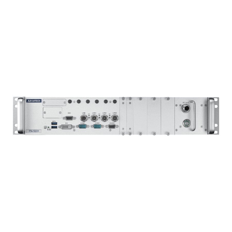
I/O Connectors Figure 2.2 ITA-5231 I/O View 2.3.1 COM Connector ITA-5231 is equipped with two RS-232/422/485 DB9 connectors. The default setting is RS-232. Table 2.5: COM Connector Pin Definitions RS-232 RS-422 RS-485 Signal Name Signal Name Signal Name TxD(-) DATA- TxD(+) DATA+ RxD(+) -
Page 22: Audio Connector
2.3.2 Audio Connector Table 2.6: Audio Connector Pin Definitions Signal Name Signal Name MICR LOUTR GND_AUD GND_AUD GND_AUD Front_JD MIC_JD LOUTL MICL 2.3.3 Digital I/O Connector ITA-5231 provides one DIO (8 bit) with DB9 type connector (four DI and four DO). Table 2.7: Digital I/O Connector Pin Definitions Signal Name Signal Name... -
Page 23: Usb Connector
2.3.4 USB Connector ITA-5231 features two USB 3.0 ports with a Type-A connector and one USB 2.0 port with an M12 A-coded female connector. The USB interface can be disabled via the system BIOS utility. Table 2.8: USB 3.0 Connector Pin Definitions Signal Name Signal Name +V5(VCC) -
Page 24: Power Input
2.3.6 Power Input Table 2.11: Power Connector Pin Definitions Signal Name Signal Name 2.3.7 DVI-I ITA-5231 reserves the main display output as DVI-I as a default. There is the option to convert this to DVI-D +VGA via a Y-cable. Table 2.12: DVI-I Signal Name Signal Name T.M.D.S. -
Page 25: Led Indicators
2.3.8 LED Indicators The ITA-5231 front panel features LEDs that are used to indicate system health and active status. The LED indicator behaviors are described and explained in the table below. Item Status Color Description The system is powered on and functioning Green normally Yellow... - Page 26 ITA-5231 User Manual...
-
Page 27: Chapter 3 System Setup
Chapter System Setup mSATA Installation ITA-EM Module Installation RTC Battery Installation Antenna Installation... -
Page 28: Introduction
Introduction The following sections provide instructions for installing the hardware modules into the ITA-5231 system. mSATA Installation ITA-5231 features one mSATA slot on the main board and three mini-PCIe slots on the carrier board. Figure 3.1 Mini-PCIe and mSATA Locations on Main Board Open the top cover of the device. -
Page 29: Ssd Installation
Figure 3.3 Mini-PCIe Installation SSD Installation ITA-5231 is equipped with one dual-SSD module socket that features two brackets To install an SDD, follow the instructions provided on the next page. Figure 3.4 SSD Bracket ITA-5231 User Manual... -
Page 30: Ita-Em Easy-Swap Module Installation
Loosen the screws on the front panel and pull out the dual SSD bracket. Install the SSD onto the bracket and secure it in place using 4 screws. Figure 3.5 SSD Module Installation ITA-EM Easy-Swap Module Installation ITA-5231 reserves a blank bracket for installing an easy-swap module to extend the system I/O. -
Page 31: Figure 3.7 Easy-Swap Module Installation
Loosen the screws in the front panel and remove the blank bracket. Insert the ITA-EM module into the bracket and secure it in place using 4 screws. Figure 3.7 Easy-Swap Module Installation Figure 3.8 COM Module (ITA-EM-SR51-001AE) ITA-5231 User Manual... -
Page 32: Figure 3.9 Poe Module (Ita-Em-Pe51-001Ae)
Figure 3.9 PoE Module (ITA-EM-PE51-001AE) Figure 3.10 CAN Module (ITA-EM-CN51-001AE) ITA-5231 User Manual... -
Page 33: Rtc Battery Installation
Figure 3.11 Battery Module (ITA-EM-BA51-00A1E) RTC Battery Installation The RTC battery can be accessed via the front panel. Open the RTC battery port cover. Insert the RTC battery into the holder and connect the cable. Close and lock the RTC battery port cover. Note! The RTC battery settings can be configured using the BIOS utility. -
Page 34: Antenna Installation
Antenna Installation ITA-5231 features antenna connectors on the front panel. Open the top cover of the device. Loosen the screws to remove the dual-SSD bracket. Remove the carriage bracket for the easy-swap module. Insert the mini-PCIe module and secure it in place using 2 screws. -
Page 35: Chapter 4 Bios Settings
Chapter BIOS Settings... -
Page 36: Introduction
This chapter explains the basic navigation of the BIOS Setup menus and how to con- figure the BIOS settings for the ITA-5231 series. With the AMI BIOS Setup program, users can modify the BIOS settings and control the device features. The Setup pro- gram features several menus with multiple items that for enabling/disabling functions and implementing changes. -
Page 37: Main Setup
Main Setup Upon entering the BIOS Setup utility, users are presented with the Main setup page. Users can always return to the Main setup page by selecting the Main tab. The Main BIOS Setup page is shown below. The Main BIOS setup page has two main frames. The left frame displays all the items accessible on the Main page. -
Page 38: Advanced Bios Setup
4.3.1 Advanced BIOS Setup Select the Advanced tab from the BIOS Setup Utility to enter the Advanced BIOS Setup page. Select any of the items in the left frame of the screen, such as CPU Con- figuration, to access the sub menu for that item. The options for any of the Advanced BIOS Setup items can be displayed by highlighting the item using the <Arrow>... - Page 39 4.3.1.1 Trusted Computing Security Device Support This item allows users to enable/disable BIOS support for the security device. The default setting is “enabled”. TPM State This item allows users to enable/disable security device. The default setting is “enabled”. ...
- Page 40 4.3.1.2 PCH-FW Configuration This page shows the version, mode, type, and SKU of the ME firmware built-in BIOS. ITA-5231 User Manual...
- Page 41 4.3.1.3 Embedded Controller Configuration This page shows the hardware data accessed by the embedded controller. Users can access this page to obtain the system temperature, voltage, or status information. Mute This item allows users to enable/disable the system audio. The default setting is “disabled”.
- Page 42 4.3.1.4 F81216 Controller Configuration ITA-5231 supports two serial ports. Users can configure the serial port in the BIOS Setup utility. Serial port 60 has a hardware reserved function. The default setting is “disabled”. Serial Port 1/2 Configuration ITA-5231 User Manual...
- Page 43 Serial Port This item allows users to enable/disable the serial port. The default setting is “enabled”. Device Settings This item allows users to view the I/O ports in operation and the IRQ number. Change Settings [1] This item allows users to optimize the serial port settings (I/O port and IRQ). The default setting is “auto”.
- Page 44 4.3.1.6 CPU Configuration This page shows the system CPU information. Hyper-Threading This item allows users to enable/disable the CPU hyper-threading function. The default setting is “enabled”. Active Processor Cores This item allows users to select the number of cores to enable for each proces- sor package.
- Page 45 Intel Virtualization Technology This item allows users to enable/disable Intel Virtualization Technology. When enabled, a VMM can utilize the additional hardware capabilities provided by Vanderpool Technology. The default setting is “enabled”. Boot Performance Mode This item allows users to select the performance state that the BIOS will set before OS handoff.
- Page 46 4.3.1.8 Network Stack Configuration Network Stack This item allows users to enable/disable the UEFI network stack. The default setting is “disabled”. ITA-5231 User Manual...
- Page 47 When the network stack is enabled, the followed page will be accessible: Ipv4 PXE Support This item allows users to enable/disable IPV4 PXE support. If disabled, the IPV4 PXE boot option will not be created. Ipv6 PXE Support This item allows users to enable/disable IPV6 PXE support.
- Page 48 4.3.1.9 CSM Configuration CSM Support This item allows users to enable/disable CSM support. The default setting is “enabled”. GateA20 Active This item is useful when the RT code is executed above 1 MB. When this is set as “upon request”, GA20 can be disabled in the BIOS utility. When set as “always”, GA20 cannot be disabled.
- Page 49 4.3.1.10 USB Configuration Legacy USB Support This item allows users to enable/disable legacy USB support. The default set- tings is “enabled”. XHCI Hand-off This item is a workaround for OS without XHCI hand-off support. The XHCI ownership changes should be conducted by the XHCI driver. ...
- Page 50 4.3.1.11 PCIE COM Port Configuration ITA-5231 supports four PCIE serial ports. Users can configure the serial ports with the following settings: Serial Port 1/2/3/4 Mode This item allows users to set the serial port mode as RS-232, RS-422, or RS- 485.
-
Page 51: Chipset Configuration
4.3.2 Chipset Configuration The PCH and SA setting can be configured via the Chipset Configuration sub-page. ITA-5231 User Manual... - Page 52 4.3.2.1 System Agent Configuration VT-d This item allows users to enable/disable VT-d function. Above 4GB MMIO BIOS assignment This item allows users to enable/disable above 4 GB MMIO BIOS assignment. When the aperture size is 2048 MB, this function is automatically disabled. ...
- Page 53 4.3.2.2 Graphics Configuration IGFX VBIOS Version This item allows users to view the current VBIOS version. Graphics Turbo IMON Current This item allows users to set the graphics turbo IMON current values (14 ~ 31). GTT Size This item allows users to select the GTT size.
- Page 54 Primary IGFX Boot Display This item allows users to select the primary video device to be activated during POST. The options are HDMI, DVI, eDP panel, and VGA. The secondary boot display options will depend on the initial selection. eDP LVDS Panel Type ...
- Page 55 4.3.2.3 PEG Port Configuration Enable Root Port This item allows users to enable/disable the root port. Max Link Speed This item allows users to configure the PEG port’s max. link speed. Detect Non-Compliant Device This item allows users to enable/disable the detect non-compliant PCIE device function.
- Page 56 4.3.2.4 PCH-IO Configuration Intel PCH RC Version This item allows users to view the current Intel PCH RC version. Intel PCH SKU Name This item allows users to view the current Intel PCH SKU name. Intel PCH Rev ID ...
- Page 57 4.3.2.5 PCI Express Configuration This page shows that the PCH supports the PCIE root ports. PCIE port 4 is assigned to i219 LAN. The items for configuration are show below. ITA-5231 User Manual...
-
Page 58: Security Configuration
PCI Express Root Port This item allows users to configure the PCI Express root port. Hot Plug This item allows users to enable/disable PCI Express hot plugging. PCIe Speed This item allows users to set the PCI Express port speed. Detect Non-Compliant Device ... -
Page 59: Boot Configuration
4.3.4 Boot Configuration Setup Prompt Timeout This item allows users to set the number of seconds to wait for the setup activa- tion key. The default setting is “1”. Bootup NumLock State This item allows users to set the <NumLock> state during bootup. The default setting is “on”. -
Page 60: Save & Exit
4.3.5 Save & Exit Save Changes and Exit This item allows users to exit the BIOS utility after saving all changes. Discard Changes and Exit This item allows users to exit the BIOS utility without saving any changes. Save Changes and Reset ... - Page 61 ITA-5231 User Manual...
- Page 62 ITA-5231 User Manual...
-
Page 63: Chapter 5 Driver Installation
Chapter Driver Installation Chipset Windows Driver Setup VGA Windows Driver Setup ME Windows Driver Setup LAN Windows Driver Setup USB 3.0 Windows Driver Setup... -
Page 64: Introduction
Introduction Advantech offers a complete range of device drivers and software supports for Win- dows program developers. Windows device drivers can be applied to the most popu- lar Windows programming tools, such as Visual C++, Visual Basic, Borland C++ Builder, and Borland Delphi. In this Chapter, Windows 7 is used as the example. -
Page 65: Chipset Windows Driver Setup
5.2.1 Chipset Windows Driver Setup Insert the driver CD into the system’s CD-ROM drive. The driver folder items should appear as shown in the image below. Navigate to the “INF” folder and click “Setup” to complete the installation. ITA-5231 User Manual... - Page 66 ITA-5231 User Manual...
- Page 67 ITA-5231 User Manual...
-
Page 68: Vga Windows Driver Setup
5.2.2 VGA Windows Driver Setup Insert the driver CD into the system’s CD-ROM drive. The driver folder items should appear as shown in the image below. Navigate to the “ME” folder and click “Setup” to complete the driver installation. 5.2.3 ME Windows Driver Setup Insert the driver CD into the system’s CD-ROM drive. -
Page 69: Lan Windows Driver Setup
5.2.4 LAN Windows Driver Setup Insert the driver CD into the system’s CD-ROM drive. The driver folder items should appear as shown in the image below. Navigate to the “LAN” folder and click “Setup” to complete the driver installation. 5.2.5 USB 3.0 Windows Driver Setup Insert the driver CD into the system’s CD-ROM driver. - Page 70 ITA-5231 User Manual...
- Page 71 ITA-5231 User Manual...
- Page 72 ITA-5231 User Manual...
-
Page 73: Chapter 6 Gpio Programming Guide
Chapter GPIO Programming Guide... -
Page 74: Digital Di/O Definition
Note! Download the specifications for programming the NXP Semiconductors’ PCA9554 GPIO IC from the NXP website. https://www.nxp.com/docs/en/data-sheet/ PCA9554_9554A.pdf?fsrch=1&sr=1&pageNum=1 Digital DI/O Definition See Section 2.3.3. Configuration Sequence ITA-5231’s GPIO is realized through the PCA9554 GPIO IC connected to ICH SMBUS. Therefore, the GPIO IC is configured and accessed through I/O space via the ICH SMBUS controller. -
Page 75: Command Byte
6.2.1 Command Byte Table 6.3: Command Byte Command Protocol Function Read byte Input port register Read/write byte Output port register Read/write byte Polarity inversion register Read/write byte Configuration register The command byte is the first byte to follow the address byte during a write transmission. -
Page 76: Pca9554 Register 2 - Polarity Inversion Register
If one GPIO pin is set to output, the input value can be read from the bit that corre- sponds to Register 1. 6.2.4 PCA9554 Register 2 – Polarity Inversion Register This register allows users to invert the polarity of the input port register data. If a bit in this register is set (write with “1”), the corresponding input port data is inverted. - Page 77 Set GPIO 00 as Output Read the SMBUS slave 0x40 Register 3 byte value. Set bit 0 of the value read in Step 1 as 0 and write it to the SMBUS slave 0x40 Register 3. Read the SMBUS slave 0x40 Register 1 byte value. Set bit 0 of the value read in Step 3 as 0 or 1 according to how low or high the output value is.
- Page 78 newiodelay(); //delay newiodelay(); //delay outportb(SMBUS_PORT + 2, 0x48); //Write SMBUS command SMB_BASE + 2. 0x48 means starting byte data transmission newiodelay(); //delay newiodelay(); //delay for (i = 0; i <= 0x100; i++) newiodelay(); //longerdelay chk_smbus_ready(); //wheater SMBUS is ready return (inportb(SMBUS_PORT + 5));...
- Page 79 moredelay(); //longerdelay for (i = 0; i <= 0x100; i++) newiodelay();//longerdelay chk_smbus_ready(); //wheater SMBUS is ready ///////////////////////////////////////////////////////////////////// chk_smbus_ready() // To decide whether SMBUS is ready or has completed the action, you should wait for a long time to check whether SMBUS has successfully transmitted the command.
- Page 80 if (data & 0x04) // If bit 2 is set (which means error occurs on SMBUS), error occurs on SMBUS which is rarely the case result = 1; //SMBUS error break; return result; ///////////////////////////////////////////////////////////////////// BYTE check_data (W ORD addr) int i; BYTE data;...
- Page 81 for (i = 0; i < 20; i++) outportb(0xeb, 0); // IO port 0xeb No real device occu- pies. Write a value to this port can realize delay function. You can also choose other method according to the real situation. ********************************************************************* GPIO Simcodes (take GPIO 00 and GPIO 07 as an example)
- Page 82 ITA-5231 User Manual...
-
Page 83: Appendix A Programming The Watchdog Timer
Appendix Programming the Watchdog Timer... -
Page 84: Introduction
Introduction The ITA-5231’s watchdog timer can be used to monitor the software operations and take corrective action if the software fails to function within the programmed period. This section describes the operation of the watchdog timer and procedures for pro- gramming it. - Page 85 Data Port: Port 0x299 Action Description Send Write data to EC Get Read data from EC Note! After writing data/commands to the 299/29A port, the IBF will be set as “1”. Users must wait for the IBF to clear to zero, before writ- ing the next data/commands to the 299/29A port.
- Page 86 Example Program //Wait IBF Empty unsigned char ECWaitIBFEmpty() unsigned char Status; Status = inportb(0x29A); //Read back Status } while (Status & 0x02); //If IBF Set? return Status; //Write non-data command (no data) to EC void EcWriteCmd (unsigned char cmd) ECWaitIBFEmpty();//Wait IBF Empty outpor tb(0x29A, (unsigned char)cmd);...
- Page 87 //Start watchdog void enable_wdt( i nt time, //Time int timebase //Time base: 0: second 1: minute unsigned int time_word; EcWriteCmd(0x29); //Write command 0x29 to stop watch dog if (timebase == 0) //Second base = 100ms * 10 time_word = time * 10; else //Minute base = 100ms * 600 time_word = time * 600;...
- Page 88 ITA-5231 User Manual...
-
Page 89: Declaration Of The Presence Condition Of The Restricted Substances Marking
Appendix Declaration of the Presence Condition of the Restricted Substances Marking... - Page 90 BSMI RoHS 限用物質含有情況標示確認表 Declaration of the Presence Condition of the Restricted Substances Marking 設備名稱:電腦 型號 (型式) :ITA-5231 Equipment name Type designation (Type) 限用物質及其化學符號 Restricted substances and its chemical symbols 單元 六價鉻 多溴聯苯 多溴二苯醚 鉛 汞 鎘 Unit Hexavalent Polybrominated Polybrominated Lead Mercury Cadmium...
-
Page 91: Chinese Language Safety Instructions And Battery Information
Appendix Chinese Language Safety Instructions and Battery Information... -
Page 92: 安全指示
安全指示 請仔細閱讀此安全操作說明。 請妥善保存此用戶手冊供日後參考。 用濕抹布清洗設備前,請從插座拔下電源線。請不要使用液體或去汙噴霧劑清洗 設備。 對於使用電源線的設備,設備周圍必須有容易接觸到的電源插座。 請不要在潮濕環境中使用設備。 請在安裝前確保設備放置在可靠的平面上,意外跌落可能會導致設備損壞。 設備外殼的開口是用於空氣對流,從而防止設備過熱。請不要覆蓋這些開口。 當您連接設備到電源插座上前,請確認電源插座的電壓是否符合要求。 請將電源線佈置在人們不易絆到的位置,並不要在電源線上覆蓋任何雜物。 請注意設備上的所有警告標識。 如果長時間不使用設備,請將其同電源插座斷開,避免設備被超標的電壓波動損 壞。 請不要讓任何液體流入通風口,以免引起火災或者短路。 請不要自行打開設備。為了確保您的安全,請由經過認證的工程師來打開設備。 如遇下列情況,請由專業人員來維修: 電源線或者插頭損壞; 設備內部有液體流入; 設備曾暴露在過於潮濕的環境中使用; 設備無法正常工作,或您無法通過用戶手冊來使其正常工作; 設備跌落或者損壞; 設備有明顯的外觀破損。 請不要把設備放置在超出我們建議的溫度範圍的環境,即不要低於 -25°C (-13 °F)或高於 60°C (140°F) ,否則可能會損壞設備。 此為 A 級產品,在生活環境中,該產品可能會造成無線電干擾。在這種情況下, 可能需要使用者對干擾採取切實可行的措施。 本產品不帶電線元件銷售,應購買已通過 CCC 認證的電線元件。 注意:電腦配置了由電池供電的即時時鐘電路,如果電池放置不正確,將有爆炸的危 險。因此,只可以使用製造商推薦的同一種或者同等型號的電池進行替換。請按照製 造商的指示處理舊電池。 根據... - Page 93 ITA-5231 User Manual...
- Page 94 No part of this publication may be reproduced in any form or by any means, such as electronically, by photocopying, recording, or otherwise, without prior written permission from the publisher. All brand and product names are trademarks or registered trademarks of their respective companies. © Advantech Co., Ltd. 2019...
Need help?
Do you have a question about the ITA-5231 Series and is the answer not in the manual?
Questions and answers