
Related Manuals for Advantech ITA-7220 Series


Summary of Contents for Advantech ITA-7220 Series
- Page 1 User Manual ITA-7220 Series Passenger Information System Computer for Railway Applications...
- Page 2 No part of this manual may be reproduced, copied, translated or transmitted in any form or by any means without the prior written permission of Advantech Co., Ltd. Information provided in this manual is intended to be accurate and reliable. How- ever, Advantech Co., Ltd.
- Page 3 Technical Support and Assistance Visit the Advantech website at http://support.advantech.com where you can find the latest information about the product. Contact your distributor, sales representative, or Advantech's customer service center for technical support if you need additional assistance. Please have the following information ready before you call: –...
- Page 4 The sound pressure level at the operator's position according to IEC 704-1:1982 is no more than 70 dB (A). DISCLAIMER: This set of instructions is given according to IEC 704-1. Advantech disclaims all responsibility for the accuracy of any statements contained herein.
- Page 5 ZONE D'ACCÈS RESTREINTE:L'équipement ne doit être installé que dans une zone d'accès restreint. DISCALIMER: Cet ensemble d'instructions est conforme à la norme IEC 704-1. Advantech décline toute responsabilité quant à l'exactitude et aux déclarations contenues dans ce document. ITA-7220 User Manual...
- Page 6 Ce produit est destiné à être alimenté par une source d'alimentation CC réperto- riée, débit 24Vdc, 1.4A; 48Vdc, 0.9A; 72Vdc, 0.5A; 110Vdc, 0.4A minimum et Tma 60 degree C, si besoin d'aide, veuillez contacter Advantech pour plus d'informations. Safety Precaution - Static Electricity Follow these simple precautions to protect yourself from harm and the products from damage.
- Page 7 Warnings, Cautions and Notes Warning! Warnings indicate conditions, which if not observed, can cause personal injury! Caution! Cautions are included to help you avoid damaging hardware or losing data. e.g.There is a danger of a new battery exploding if it is incorrectly installed.
- Page 8 Ground Screw Connection for DC Power Source Attention: Only trained service personnel are authorized to install and remove the DC power supply, and make the connections to and disconnections from the DC power source. The customer is responsible for ensuring that only trained service personnel install or remove the power cable.
-
Page 9: Table Of Contents
Contents Chapter General Information ......1 Introduction ....................2 Production Features.................. 2 1.2.1 General ..................2 1.2.2 Display ..................2 1.2.3 Power Consumption..............2 Hardware Specifications ................2 1.3.1 System Block Diagram..............3 Figure 1.1 ITA-7220 System Block Diagram ....... 3 Mechanical Specifications................. - Page 10 3.2.5 Boot .................... 34 3.2.6 Save & Exit ................. 35 Appendix A Exploded & Setting Diagram.... 37 Exploded Diagram .................. 38 Figure A.1 Exploded Diagrams ..........38 Setting Diagram ..................38 Figure A.2 Setting Diagrams............38 Appendix B Watchdog Timer Sample Code ..
-
Page 11: Chapter 1 General Information
Chapter General Information This chapter gives background information on the ITA-7220 Passenger Information System. Sections include: Introduction General Specifications Power Information Dimensions... -
Page 12: Introduction
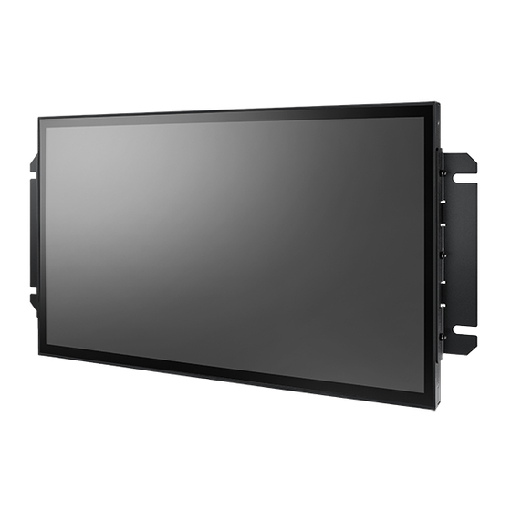
Introduction The ITA-7220 is a dedicated panel computer for rolling stock passenger information systems. ITA-7220 has IO ports, such as LAN, USB, etc. and wide temperature range (-25 ° C to + 55 ° C) support. Production Features 1.2.1 General ... -
Page 13: System Block Diagram
1.3.1 System Block Diagram M12 A-code 4 pin male M12 A-code M12 X-code M12 X-code USB A type 4pin female 8 pin female 8 pin female 22" Panel +110V,+72V +48V,+24V USB2.0 USB2.0 Giga LAN Giga LAN LVDS LCD Voltage : 5V Power Board +12V Backlight... -
Page 14: Mechanical Specifications
Mechanical Specifications 1.4.1 Dimensions 575 x 300 x56 (Unit:mm) Figure 1.2 ITA-7220 Mechanical dimension drawing 1.4.2 Weight 6.8kg Power Requirements 1.5.1 System Power Power Input: 24Vdc@ 1.4A Power Input: 48Vdc@ 0.9A Power Input: 72Vdc@ 0.5A Power Input: 110Vdc@ 0.4A 1.5.2 RTC Battery... -
Page 15: Environment Specification
Environment Specification 1.6.1 Operation Temperature With Industrial Grade SSD: -25 ~ 55 °C (-13 ~131 °F), with air flow. Speed=0.7 m/sec 1.6.2 Relative Humidity 95%@ 40 °C (non-condensing) 1.6.3 Storage Temperature -40 ~ 85 °C (-40 ~ 185 °F) 1.6.4 Vibration during operation ... - Page 16 ITA-7220 User Manual...
-
Page 17: Chapter 2 Hardware Information
Chapter Hardware Information This chapter introduces external I/ O and the installation of the ITA- 7220 Hardware. -
Page 18: Ita-7220 I/O Connectors
ITA-7220 I/O Connectors ITA-7220 External I/O Connectors 2.2.1 Power Input Connector ITA-7220 comes with a M12 A-coded connector that carries VDC external power input. Figure 2.1 Power Input Connector Table 2.1: Power Input Connector Signal Signal ITA-7220 User Manual... -
Page 19: Usb M12 Connector
2.2.2 USB M12 Connector Figure 2.2 M12 USB connector Table 2.2: USB connector of M12 A-Coded Signal Signal Data - Data + 2.2.3 M12 X-Coded LAN Connector Figure 2.3 M12 X -coded connector Table 2.3: LAN Connector of M12 X-Coded Signal Signal MDX0+... -
Page 20: Usb Connector
2.2.4 USB Connector Figure 2.4 USB Connector Table 2.4: USB connector pin assignments Signal Signal USB data- USB data+ 2.2.5 DVI-D Connector Figure 2.5 DVI Connector Table 2.5: DVI-D Connector Signal Signal TMDS Data 2- TMDS data 2+ DDC clock DDC data TMDS Data 1- TMDS Data 1+... -
Page 21: Chapter 3 Bios Settings
Chapter BIOS Settings... -
Page 22: Bios Setup
BIOS Setup With the AMIBIOS Setup program, users can modify the BIOS settings and control various system features. This chapter describes the basic navigation of the ITA-7220 BIOS Setup Utility menu. AMI's BIOS ROM has a built-in setup program that allows users to modify the basic system configuration. - Page 23 The Main BIOS setup page comprises two main frames. All configurable options are displayed in the left frame. Grayed-out options cannot be configured, whereas the options presented in blue can be configured. The key legend is displayed in the right frame.
-
Page 24: Advanced Bios Features
3.2.2 Advanced BIOS Features Select the Advanced tab of the BIOS Setup Utility menu to access the Advanced BIOS setup page. Users can select any item, such as CPU Configuration, in the left frame of the screen to access the submenu for that item. Users can view the Advanced BIOS setup options by highlighting various items using the <Arrow>... - Page 25 3.2.2.1 ACPI Settings Configuration Enable ACPI Auto Configuration Enable or disable BIOS ACPI auto configuration. Enable Hibernation Enables or Disables System ability to Hibernate (OS/S4 Sleep State). This option may be not effective with some OS. ACPI Sleep State Select the highest ACPI sleep state the system will enter when the Suspend button is pressed.
- Page 26 3.2.2.2 Super I/O Configuration Serial Port 1 Configuration Set Parameters of Serial Port 1. 3.2.2.3 H/W Monitor ITA-7220 User Manual...
- Page 27 Pc Health Status This page displays all the information about system Temperature/Voltage. 3.2.2.4 S5 RTC Wake Settings Wake system with Fixed Time Enable or disable System wake on alarm event. Selecting FixedTime, system- will wake on the hr:min:sec specified. Selecting DynamicTime, System will wake on the current time + Increase minute(s).
- Page 28 3.2.2.5 Serial Port Console Redirection Console Redirection This item allows users to enable or disable console redirection for Microsoft Windows Emergency Management Services (EMS). Console Redirection This item allows users to configure console redirection detail settings. ITA-7220 User Manual...
- Page 29 3.2.2.6 CPU Configuration PPS Support This item allows you to enable or disable the ACPI _PPC, _PSS, and _PCT objects. Limit CPUID Maximum Disabled for Windows XP. Execute Disable Bit XD can prevent certain classes of malicious buffer overflow attacks when com- bined with a supporting OS (Windows Server 2003 SP1, Windows XP SP2,SuSE Linux 9.2, RedHat Enterprise 3 Update 3.) Intel Virtualization Technology...
- Page 30 3.2.2.7 PPM Configuration CPU C state Report Enable/Disable CPU C state report to OS. Max CPU C-state This option controls Max C states that the processor will support. S0ix Enable/Disable CPU S0ix state. ITA-7220 User Manual...
- Page 31 3.2.2.8 IDE Configuration Serial-ATA (SATA) Enable / Disable Serial ATA. SATA Test Mode Test Mode Enable / Disable. SATA Speed Support SATA Speed Supports Gen1 or Gen2. SATA ODD Port SATA ODD is Port0 or Port1. ...
- Page 32 3.2.2.9 Miscellaneous Configuration OS Selection OS Selection to choose Windows 8.x / Windows 7. 3.2.2.10 CSM Configuration ITA-7220 User Manual...
- Page 33 CSM Support Enable/Disable CSM Support. GateA20 Active This items is useful when RT code is executed above 1MB. When this is set as "UPON RQUEST", GA20 can be disabled using BIOS services. When it's set as "Always", it does not allow disabling GA20. ...
- Page 34 XHCI Hand-Off This is a workaround for OS without XHCI hand-off support. The XHCI owner- ship change should be claimed by the XHCI driver. EHCI Hand-Off This is a workaround for OS without EHCI hand-off support. The EHCI owner- ship change should be claimed by EHCI driver.
-
Page 35: Chipset Configuration
Intel (R) AT Platform PBA Enable/Disable BIOS AT code from running. 3.2.3 Chipset Configuration North Bridge Details for North Bridge items. South Bridge Details for South Bridge items. ITA-7220 User Manual... - Page 36 3.2.3.1 North Bridge Intel IGD Configuration Config Intel IGD settings. Graphics Power Management Control Graphics Power Management Control options. LCD Control LCD Control. Max TOLUD Maximum value of TOLUD. ITA-7220 User Manual...
- Page 37 3.2.3.2 Intel IGD Configuration Intel IGD Configuration Config Intel IGD settings. IGD Turbo Enable Enable: Enable IGD Turbo Enable. Disable: IGD Turbo Disable. GFX Boost Enable/Disable GFX boost. PAVC Enable/Disable protected audio video control. DVMT Pre-Allocated Select DVMT 5.0 Pre-Allocated (Fixed) graphics memory size used by the Inter- nal graphics device.
- Page 38 3.2.3.3 Graphics Power Management Control RC6 (Render Standby) Check to enable render standby support. 3.2.3.4 LCD Control ITA-7220 User Manual...
- Page 39 Primary IGFX Boot Display Select the video device which will be activated during POST. This has no effect if external graphics are present. Secondary boot display selection will appear based on your selection. VGA modes will be supported only on the primary dis- play.
- Page 40 BIOS Read/Write Protection Enable or Disable BIOS SPI region read/write protect. 3.2.3.6 Azalia HD Audio Audio Controller Control Detection of the Azalia device. Disabled = Azalia will be unconditionally disabled. Enabled = Azalia will be unconditionally Enabled. Auto = Azalia will be enabled if present disabled otherwise.
- Page 41 3.2.3.7 USB Configuration XHCI Mode Mode of operation of xHCI controller. USB2 Link Power Management Enable/Disable USB2 Link Power Management. USB 2.0(EHCI) Support Control the USB EHCI (USB 2.0) functions. One EHCI controller must always be enabled. ...
- Page 42 3.2.3.8 PCI Express Configuration PCI Express Port 0 Enable or Disable the PCI Express Port 0 in the chipset. Hot Plug Enable or disable PCI Express Hot Plug. Speed Configure PCIe port speed. ITA-7220 User Manual...
-
Page 43: Security Configuration
3.2.4 Security Configuration Select the Security tab from the main BIOS Setup Utility menu. All security setup options, such as password and virus protection, can be accessed from this menu. To access the submenu of any item, select the item and press <Enter>: ... -
Page 44: Boot
3.2.5 Boot Setup Prompt Timeout Number of seconds that the firmware will wait before initiating the original default boot selection. A value of 0 indicates that the default boot selection is to be initiated immediately on boot. A value of 65535(0xFFFF) indicates that firm- ware will wait for user input before booting. -
Page 45: Save & Exit
3.2.6 Save & Exit Save Changes and Exit This item allows you to exit system setup after saving the changes. Discard Changes and Exit This item allows you to exit system setup without saving any changes. Save Changes and Reset ... - Page 46 ITA-7220 User Manual...
-
Page 47: Exploded & Setting
Appendix Exploded & Setting Diagram... -
Page 48: Exploded Diagram
Exploded Diagram Figure A.1 Exploded Diagrams Setting Diagram Figure A.2 Setting Diagrams ITA-7220 User Manual... -
Page 49: Watchdog Timer Sample Code
Appendix Watchdog Timer Sample Code... -
Page 50: Watchdog Timer Sample Code
Watchdog Timer sample code #include <cstdlib> #include <cstdio> #include <sys/io.h> #include <unistd.h> using namespace std; const unsigned int baseAddress = 0xA00; void setWDT(unsigned char); int main(int argc, char** argv) unsigned char inputData; printf("Please enter a number(1 ~ 255):"); scanf("%d", &inputData); setWDT(inputData);... - Page 51 ITA-7220 User Manual...
- Page 52 No part of this publication may be reproduced in any form or by any means, electronic, photocopying, recording or otherwise, without prior written permis- sion of the publisher. All brand and product names are trademarks or registered trademarks of their respective companies. © Advantech Co., Ltd. 2019...
Need help?
Do you have a question about the ITA-7220 Series and is the answer not in the manual?
Questions and answers