Table of Contents
Advertisement
Advertisement
Table of Contents

Summary of Contents for Advantech IPC-610
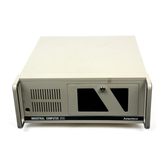
- Page 1 IPC-610 Industrial PC Chassis...
- Page 2 Copyright Notice This document is copyrighted, September 1998, by Advantech Co., Ltd. All rights are reserved. Advantech Co., Ltd. reserves the right to make improvements to the products described in this manual at any time without notice. No part of this manual may be reproduced, copied, translated or transmitted in any form or by any means without the prior written permission of Advantech Co., Ltd.
-
Page 3: Table Of Contents
Figure A-1: IPC-610 with PS/2 size power supply ................... 6 A.2 The Backplane ............................7 Figure A-3: Rear window of IPC-610 for standard 14-slot backplane, with PS/2 size power supply ..7 A.3 AT Motherboard ............................8 Figure A-4: Rear window of IPC-610 for standard AT motherboard ............8 A.4 ATX Motherboard ............................ -
Page 4: Chapter 1 General Information
CPU, video, disk controller, and I/O interface cards. They can be conveniently installed and replaced from the top of the unit. The IPC-610 will withstand shock, vibration, dust, and a wide range of operating temperatures in harsh industrial environments. The chassis is positively pressurized by two filtered push-pull cooling fans to exclude dust and dirt. -
Page 5: Dimensions
• Vibration (operating): 5 ~ 17 Hz, 0.1" double amplitude displacement; 17 ~ 500 Hz, 1.5 g acceleration peak to peak • Shock (operating): 10 g acceleration peak (11 ms duration) • Safety: C-UL approved • EMI: Meets FCC/VDE Class A • CE compliant 1.3 Dimensions Unit = mm Figure 1-1: IPC-610 dimensions IPC-610 User's Manual... -
Page 6: Chapter 2 System Setup
Chapter 2 System Setup Setting up your IPC-610 requires only a screwdriver and a small amount of time. Before you begin, you should also gather together all of the cards you plan to install, as well as the keyboard you plan to use. -
Page 7: The Hold-Down Clamp
2.3 The Hold-down Clamp The IPC-610 uses a hold-down clamp to ensure the plug-in cards are securely fastened. It also offers protection against shock and vibration. To install your cards into the passive backplane, proceed as follows: 1. Detach the hold-down clamp by removing the two screws located at each end and lifting it off the chassis. -
Page 8: Replacing The Filter
2. Remove the filter out by gently pulling the tab and sliding the filter to the right. 3. Slide a new filter in until it snaps into place. 4. Close and lock the lockable door. Figure 2-8: Replacing the filter IPC-610 User's Manual... -
Page 9: Appendix A Rear Cover And Window
Appendix A Rear Cover and Window A.1 Changing the Rear Cover According to Power Supply Used Figure A-1: IPC-610 with PS/2 size power supply Figure A-2: IPC-610 with redundant power supply IPC-610 User's Manual... -
Page 10: The Backplane
1. Select the backplane you want to install, such as the PCA-6114, PCA-6114P4, PCA-6114P4R, PCA-6114P7, PCA-6114P10, etc. 2. To change the backplane's rear window, see Fig. A-3. Figure A-3: Rear window of IPC-610 for standard 14-slot backplane, with PS/2 size power supply IPC-610 User's Manual... -
Page 11: At Motherboard
A.3 AT Motherboard 1. Make sure that the motherboard supports AT power. 2. To change the rear window for standard AT motherboards, see Fig. A-4. Figure A-4: Rear window of IPC-610 for standard AT motherboard IPC-610 User's Manual... -
Page 12: Atx Motherboard
A.4 ATX Motherboard 1. Make sure that the motherboard supports ATX power. 2. To change the rear window for standard ATX motherboards, see Fig. A-5. Figure A-5: IPC-610 ATX chassis component layout IPC-610 User's Manual... -
Page 13: Appendix B Exploded Diagrams
Appendix B Exploded Diagrams Figure B-1: IPC-610 exploded diagram (internal components) IPC-610 User's Manual... -
Page 14: Figure B-2: Ipc-610 Exploded Diagram (Case Components)
Figure B-2: IPC-610 exploded diagram (case components) IPC-610 User's Manual... -
Page 15: Figure B-3: Ipc-610 Exploded Diagram (Speaker, Led, Fan)
Figure B-3: IPC-610 exploded diagram (speaker, LED, fan) IPC-610 User's Manual... -
Page 16: Appendix C Safety Instructions
The sound pressure level at the operator's position according to IEC 704-1:1982 is equal to or less than 70 dB(A). DISCLAIMER: This set of instructions is provided according to IEC 704-1. Advantech disclaims all responsibility for the accuracy of any statements contained herein. -
Page 17: Wichtige Sicherheishinweise
Wenn das Gerät deutliche Anzeichen eines Defektes aufweist. Der arbeitsplatzbezogene Schalldruckpegel nach DIN 45 635 Teil 1000 beträgt 70dB(A) oder weiger. DISCLAIMER: This set of instructions is provided according to IEC704-1. Advantech disclaims all responsibility for the accuracy of any statements contained herein.


Need help?
Do you have a question about the IPC-610 and is the answer not in the manual?
Questions and answers