
Related Manuals for Advantech ITA-168 Series


Summary of Contents for Advantech ITA-168 Series
- Page 1 User Manual ITA-168/178 Series Fanless Embedded Intel J6412 Quad Core Compact Industrial Computer...
- Page 2 No part of this manual may be reproduced, copied, translated, or transmitted in any form or by any means without the prior written permission of Advantech Co., Ltd. The information provided in this manual is intended to be accurate and reliable.
- Page 3 Advantech has come to be known. Your satisfaction is our primary concern. Here is a guide to Advantech's customer services.
- Page 4 Advantech doesn’t provide power component for this product, users should pur- chase power components with CCC certificate. CAUTION: Batteries are at risk of exploding if incorrectly replaced. Replace only with the same or equivalent type as recommended by the manufacturer.
- Page 5 Safety Precautions - Static Electricity Follow these simple precautions to protect yourself from harm and the products from damage. To avoid electrical shock, always disconnect the power from the PC chassis before manual handling. Do not touch any components on the CPU card or other cards while the PC is powered on.
- Page 6 ITA-168/178 User Manual...
-
Page 7: Table Of Contents
Contents Chapter Overview..........1 Introduction ....................2 Specifications .................... 2 Power Information ..................3 Table 1.1: Power ................. 3 Environmental Specifications ..............3 Table 1.2: Environmental Specifications ........3 Dimension Diagram................... 4 Figure 1.1 Dimension Diagram of ITA-168 ........4 Figure 1.2 Dimension Diagram of ITA-178 ........5 Exploded Diagram.................. - Page 8 Table 2.12:LVDS Connector ............18 2.4.9 LPT Connector................19 Table 2.13:LPT Connector ............19 Chapter System Setup ........21 Introduction ..................... 22 3.1.1 Installing an SSD ................ 22 Figure 3.1 Installing an 2.5" SSD on ITA-168 ......22 Figure 3.2 Installing an 2.5" SSD on ITA-178......23 3.1.2 Installing the Tripods and the Top Cover........
-
Page 9: Chapter 1 Overview
Chapter Overview This chapter provider general Information about the ITA-168/ 178. -
Page 10: Introduction
Introduction ITA-168/178 is a fanless embedded compact industrial computer with an Atom® dual core processor and wide voltage input, which is specially designed for intelligent transportation and self-service equipment. This powerful computing platform can work 24 hours a day, 7 days a week. Specifications Processor: Intel®... -
Page 11: Power Information
Power Information ITA-168/178 supports DC 9 ~ 36 V wide voltage input. (ITA-168-10A1 is 12V DC input). Table 1.1: Power DC voltage input 9 V - 36 V or 12 V DC current 6.5 A - 3.25 A DC power interface 2P Phoenix terminal (European Standard) Environmental Specifications Table 1.2: Environmental Specifications... -
Page 12: Dimension Diagram
Dimension Diagram Figure 1.1 Dimension Diagram of ITA-168 ITA-168/178 User Manual... -
Page 13: Exploded Diagram
Figure 1.2 Dimension Diagram of ITA-178 Exploded Diagram Figure 1.3 Exploded Diagram of ITA-168 ITA-168/178 User Manual... - Page 14 Table 1.3: ITA-168 Part List Main board HDD bracket Front panel Fixed tripod Bottom cover Heat sink HDD (not included) Figure 1.4 Exploded Diagram of ITA-178 Table 1.4: ITA-168 Part List Bottom cover Fixed tripod Fixed tripod Base HDD bracket HDD (not included) Front panel CFast extraction module...
-
Page 15: Chapter 2 H/W Installation
Chapter H/W Installation This chapter provides H/W Instal- lation about the ITA-168/178. -
Page 16: Introduction
Introduction The following sections show the internal jumpers setting and the external connectors pin assignment for application integration. System Status Indicators 2.2.1 System Status LED Indicators LEDs in the centre and on the left of the switch indicates system healthy and active status. -
Page 17: Jumpers And Connector
Jumpers and Connector 2.3.1 Jumper Description You may configure the ITA-168/178 to match the needs of your application by setting jumpers. A jumper is a metal bridge used to close an electric circuit. It consists of two metal pins and a small metal clip (often protected by a plastic cover) that slides over the pins to connect them. -
Page 18: Jumper And Connector Location
2.3.2 Jumper and Connector Location The board has a number of connectors and jumpers that allow you to configure your system to suit your application. The table below lists the function of each of the con- nectors and jumpers.The locations of jumpers and connector on the board are shown in Fig 2.3 and Fig 2.4. - Page 19 Figure 2.4 Expansion I/O Card Connectors and Jumpers Location Table 2.3: JLVDS1: LVDS Voltage Selection Closed Pins Setting +12V 4/-6 +3.3V (Default) +12V +3.3V ITA-168/178 User Manual...
- Page 20 Table 2.4: JCOMS1: Clear COMS Selection Closed Pins Setting Normal (+V3.3_SB)* Clear CMOS selection *Default setting Default setting Clear CMOS selection Table 2.5: VCCGPIO1: GPIO Voltage Selection Closed Pins Setting +V3.3_SB +V5_SB (Default) +V3.3 +V5_SB +V3.3_SB Table 2.6: PSON1: Start-up Mode Selection Closed Pins Setting AT mode...
-
Page 21: I/O Connectors
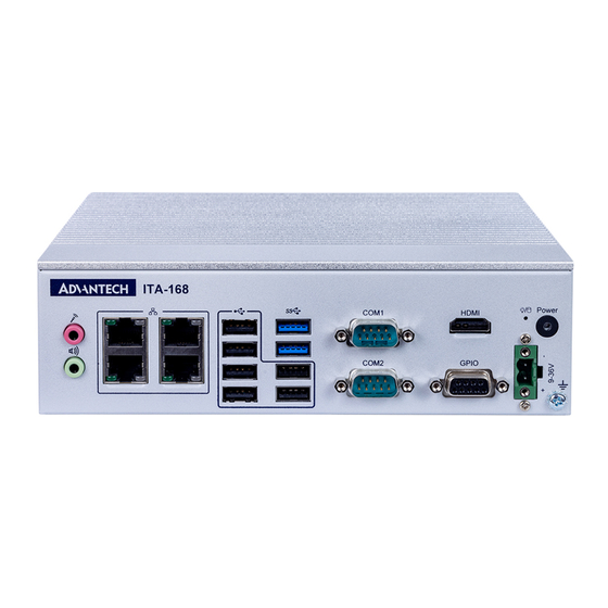
I/O Connectors Figure 2.5 ITA-168-00A1 Front I/O Connectors Figure 2.6 ITA-168-L0A1 Front I/O Connectors Figure 2.7 ITA-178-00A1 Front I/O Connectors ITA-168/178 User Manual... -
Page 22: Com Connectors
Figure 2.8 ITA-168 Rear I/O Connectors Figure 2.9 ITA-178 Rear I/O Connectors 2.4.1 COM Connectors ITA-168 provides six D-sub 9-pin interfaces, among which COM1-2 supports RS-232/ 422/485, and COM3-6 only contains RS-232 of RX/TX. ITA-178 provides fourteen D- sub 9-pin interfaces, among which COM1-6 supports RS-232/422/485, and COM7- 14 only contains RS-232 of RX/TX. -
Page 23: Usb Connectors
2.4.2 USB Connectors ITA-168/178 provides six USB2.0 connectors and two USB3.0 connectors. Table 2.8: USB Connectors USB 2.0 Signal Name USB 3.0 Signal Name +V5(VCC) +V5(VCC) USB_data- USB_data- USB_data+ USB_data+ ITA-168/178 User Manual... -
Page 24: Vga Connectors
2.4.3 VGA Connectors ITA-178 offers two D-sub 15-pin female connectors. Table 2.9: VGA Connectors Signal Name Green Blue DDC-DATA H-SYNC V-SYNC DDC-CLK 2.4.4 DIO Connector ITA-168/178 provides an 8-bit DIO port and a 24-bit DIO port respectively to be con- figured through SUSI. -
Page 25: Lan Connector
2.4.6 LAN Connector ITA-168/178 series provide four Intel I226V Ethernet controllers, which are fully com- pliant with IEEE 802.3u 10/100/2500 Mbps standard. When linked, the green LEDs are flashing. When linked to 2.5G Ethernet, the grey lEDs are always on and glow green, and while linked to Gigabit Ethernet, they are always on and glow orange. -
Page 26: Lvds Connector
2.4.8 LVDS Connector ITA-178 provides a LVDS connector to be connected to a monitor through a cable. Table 2.12: LVDS Connector Signal Name Signal Name TXL0+ TXL1+ TXL2+ TXL3+ TXLCLK- TXL0- TXL1- TXL2- TXL3- INVVCC BLENABLE TXLCLK+ LCDVCC ITA-168/178 User Manual... -
Page 27: Lpt Connector
2.4.9 LPT Connector ITA-1711-S0A1E provides a LVDS connector (in accessory box for users to change by themselves), which could connect a monitor through cables. Table 2.13: LPT Connector Signal Name Signal Name LPT_z_STB# LPT_AFD# LPT_z_PD0 LPT_ERR# LPT_PD1 LPT_INIT# LPT_PD2 LPT_SLIN# LPT_PD3 LPT_PD4 LPT_PD5... - Page 28 ITA-168/178 User Manual...
-
Page 29: Chapter 3 System Setup
Chapter System Setup This chapter introduces the instal- lation process of ITA-168/178. -
Page 30: Introduction
Introduction The following procedures will instruct you to install all modules into the ITA-168/178 system. 3.1.1 Installing an SSD ITA-168/178 provides SSD brackets, and the installation method is shown below. Figure 3.1 Installing an 2.5" SSD on ITA-168 ITA-168/178 User Manual... - Page 31 Figure 3.2 Installing an 2.5" SSD on ITA-178 ITA-168/178 User Manual...
-
Page 32: Installing The Tripods And The Top Cover
3.1.2 Installing the Tripods and the Top Cover Align the two tripods with the screw holes at the side wall of the chassis and lock them with screws. Align the top cover with the screw holes in the bends of the front panel and the base and then lock them with screws. -
Page 33: Installing The Cfast Card Module
3.1.3 Installing the CFast Card Module Please follow the below steps to install CFast card. Loosen the two screws in the CFast module and pull it out. Insert the CFast card into the slot on the module Return and screw the CFast module. Figure 3.5 Installing the CFast Card Module on ITA-178 ITA-168/178 User Manual... - Page 34 ITA-168/178 User Manual...
-
Page 35: Chapter 4 Ami Bios
Chapter AMI BIOS This chapter introduces how to configure AMI BIOS. -
Page 36: Introduction
Introduction With the AMI BIOS Setup program, you can modify BIOS settings and control the special features of your computer. The Setup program uses a number of menus for making changes and turning special features on or off. This chapter describes the basic navigation of the ITB-213 setup screens. -
Page 37: Main Menu
Main Menu Press <Del> to enter AMI BIOS CMOS Setup Utility, the Main Menu will appear on the screen. Use arrow keys to select among the items and press <Enter> to accept or enter the sub-menu. The Main BIOS setup screen has two main frames. The left frame displays all the options that can be configured. -
Page 38: Advanced Bios Setup
4.3.1 Advanced BIOS Setup Select the Advanced tab from the ITB-213 setup screen to enter the Advanced BIOS Setup screen. You can select any of the items in the left frame of the screen, such as CPU Configuration, to go to the sub menu for that item. You can display an Advanced BIOS Setup option by highlighting it using the <Arrow>... - Page 39 4.3.1.1 CPU Configuration This page shows the system CPU information. Active Processor Cores This item allows users to select the number of cores to enable for each proces- sor package. The default setting is “all”. Intel (VMX) Virtualization Technology ...
- Page 40 4.3.1.2 Power & Performance CPU - Power Management Control This item allows users to control the CPU - Power. ITA-168/178 User Manual...
- Page 41 Intel(R) SpeedStep(tm) This item allows users to enable/disable more than two frequency ranges sup- port. Turbo Mode This item allows user to enable/disable Turbo Mode. C states Enable/disable CPU Power Management. Allows CPU to go to C states when it's not 100% utilized.
- Page 42 4.3.1.3 PCH-FW Configuration This page shows the version, mode, type, and SKU of the ME firmware built-in BIOS. ME State This item allows users to enable/disable the ME State. When disabled ME will be put into ME temporarily disabled mode. ITA-168/178 User Manual...
- Page 43 Firmware update Configuration – Me FW Image Re-Flash Enable/disable Me FW Image Re-Flash function. ITA-168/178 User Manual...
- Page 44 PTT Configuration TPM Device Selection This option enables users to choose between PTT (Platform Trust Technology) or discrete TPM (Trusted Platform Module). PTT: Enables PTT in SkuMgr. dTPM: Disables PTT in SkuMgr. (If the hardware has TPM, TPM can be used ...
- Page 45 4.3.1.4 Trusted Computing Security Device Support This item allows users to enable/disable BIOS support for the security device. The default setting is “enabled”. SHA256 PCR Bank This item allows users to enable/disable SHA256 PCR Bank. SHA384 PCR Bank ...
- Page 46 4.3.1.5 ACPI Settings Enable ACPI Auto Configuration Enable or disable BIOS ACPI auto configuration. Enable Hibernation Enables or Disables System ability to Hibernate (OS/S4 Sleep State). This option may be not effective with some OS. ACPI Sleep State ...
- Page 47 4.3.1.6 Hardware Monitor This page shows the hardware data. Users can access this page to obtain the system temperature, and voltage information. 4.3.1.7 NCT6126D Super IO Configuration ITA-168/178 User Manual...
- Page 48 Serial Port 1/2/3/4/5/6 Configuration – Serial Port This item allows users to enable/disable the serial port. The default setting is “enabled”. Device Settings – This item allows users to view the I/O ports in operation and the IRQ number. –...
- Page 49 4.3.1.8 NCT5124DSEC/TRD Super IO Configuration Serial Port 1/2/3/4 Configuration ITA-168/178 User Manual...
- Page 50 4.3.1.9 Serial Port Console Redirection Console Redirection This item allows users to enable/disable the console redirection function. The default setting is “disabled”. Console Redirection Settings When the console redirection function is enabled, this item becomes available. The settings specify how the host computer and remote computer exchange data.
- Page 51 4.3.1.10 USB Configuration USB Mass Storage Driver Support This item allows users to enable/disable USB mass storage driver support. USB Transfer Timeout This item allows users to set the timeout value for control, bulk, and interrupt transfers. Device reset time-out ...
- Page 52 4.3.1.11 Network Stack Configuration Network Stack This item allows users to enable/disable the UEFI network stack. The default setting is “disabled”. When the network stack is enabled, the followed page will be accessible: ITA-168/178 User Manual...
-
Page 53: Chipset Configuration
Ipv4 PXE Support This item allows users to enable/disable IPV4 PXE support. If disabled, the IPV4 PXE boot option will not be created. Ipv4 HTTP Support This item allows users to enable/disable IPv4 HTTP support. If disabled, the IPV4 HTTP boot option will not be created. - Page 54 4.3.2.1 System Agent Configuration Memory Configuration – VT-d This item allows users to enable/disable VT-d function. ITA-168/178 User Manual...
- Page 55 Graphics Configuration – Primary Display This item allows users to select which of Auto/IGFX Graphics device as Pri- mary Display or select SG for Switchable Gfx. Internal Graphics – This item allows users to keep IGFX enabled based on the setup options. ITA-168/178 User Manual...
- Page 56 ITB-172 HDMI Configuration – LCD Panel Type This item allows users to select LCD panel used by Internal Graphics Device by selecting the appropriate setup item. Backlight Brightness – This item allows users to set the backlight brightness. ITA-168/178 User Manual...
- Page 57 4.3.2.2 PCH-IO Configuration Switch MiniPCIE Slot This item allows users to Switch MiniPCIE Slot to PCIE/USB. PCIE Wake This item allows users to Enable/Disable PCIE Wake. USB Power off Under S3/S4/S5 This item allows users to Enable/Disable USB Power Off Under S3/S4/S5. State After G3 ...
- Page 58 PCI Express Configuration PCI ExpressRoot Port 1/2/3/4/5/7 – PCI Express Root Port 1/2/3/4/5/7 This item allows users to configure the PCI Express root port 1/2/3/4/5/7. PCIe Speed – This item allows users to set the PCI Express port speed. ITA-168/178 User Manual...
- Page 59 PCIE clocks – Clock0/1/2/3/4/5/ assignment Platform-POR = clock is assigned to PCIe port or LAN according to board layout. Enabled = keep clock enabled even if unused. Disabled = Disable clock. – CIkReq for Clock0/1/2/3/4/5/ Platform-POR = CLKREQ signal is assigned to CLKSRC according to board layout.
- Page 60 SATA Configuration – SATA Controller(s) This item allows users to enable/disable SATA Device. – Port 0/1 This item allows users to enable/disable the port0/1. ITA-168/178 User Manual...
-
Page 61: Security Configuration
4.3.3 Security Configuration Administrator Password This item allows users to set the administrator password. The ideal password length is between 3 and 20 characters. User Password This item allows you to set user passwords. The ideal password length is between 3 and 20 characters. - Page 62 Secure Boot ITA-168/178 User Manual...
-
Page 63: Boot Configuration
4.3.4 Boot Configuration Setup Prompt Timeout This item allows users to set the number of seconds to wait for the setup activa- tion key. The default setting is “1”. Bootup NumLock State This item allows users to set the <NumLock> state during bootup. The default setting is “on”. -
Page 64: Save & Exit
4.3.5 Save & Exit Save Changes and Exit This item allows users to exit the BIOS utility after saving all changes. Discard Changes and Exit This item allows users to exit the BIOS utility without saving any changes. Save Changes and Reset ... -
Page 65: Chapter 5 Driver Installation
Chapter Driver Installation This chapter describes how to Install drivers. -
Page 66: Introduction
Introduction Advantech offers a complete range of device drivers and software supports for Win- dows programming developers. You can apply the device drivers to the most popular Windows programming tools, such as Visual C++, Visual Basic, Borland C++ Builder and Borland Delphi. -
Page 67: Chipset Windows Driver Setup
5.2.1 Chipset Windows Driver Setup Unzip "ITA-168 & ITA-178_chipset_win10 (64bit).zip”, and double click "SetupChip- set.exe" to complete the driver installation. 5.2.2 Graphic Windows Driver Setup Unzip "ITA-168 & ITA-178_graphic_win10 (64bit).zip", and double click "Installer.exe" to complete the driver installation. ITA-168/178 User Manual... -
Page 68: Lan Windows Driver Setup
5.2.3 LAN Windows Driver Setup Unzip "ITA-168 & ITA-178_Lan_Win10(64bit).zip", right click "e2f.inf" and select Install to complete the driver installation. 5.2.4 AUDIO Windows Driver Setup Unzip "ITA-168 & ITA-178_Audio_Win10 (64bit).zip", right click "e2f.inf" and select Install to complete the driver installation. ITA-168/178 User Manual... -
Page 69: Chapter 6 Gpio Programming Guide
Chapter GPIO Programming Guide This chapter introduces GPIO pro- gramming Guide. -
Page 70: Configuration Sequence
Configuration Sequence ITA-168/178’s on-board GPIO with LPC bus operates by Lattice CPLD. The configuration and access to CPLD GPIO IC is completed by accessing the sys- tem’s IO Space. Mapping between GPIO IO Space and corresponding GPIO pins: Port GPO : IO 0xC10~0xC12 (bit0-bit23) 0xC10:bit0~bit7 GPO(1~8) 0xC11:bit0~bit7 GPO(9~16) 0xC12:bit0~bit7 GPO(17~24) -
Page 71: Function Call Reference
Function Call Reference GPIO Analog Code (C language pseudocode) GPO 4 High Output: unsigned char data; data = inportb(0xC10); //First read corresponding IO Space register value data |= 0x08; //00001000B, set bit 03 as‘1’, meaning output High outportb(0xC10, data); //output value Read GPI 9 Input Value: unsigned char data;... - Page 72 ITA-168/178 User Manual...
-
Page 73: Appendix A Programming The Watchdog Timer
Appendix Programming the Watchdog Timer... -
Page 74: Watchdog Timer Overview
The ITA-168/178's watchdog timer can be used to monitor system software operation and take corrective action if the software fails to function during the programming. This section describes the operation of the watchdog timer and how to program it. Watchdog Timer Overview The watchdog timer is built into the super I/O controller SMSC SCH3114. -
Page 75: Program Examples
Program Examples Enable watchdog timer and set 10 sec. as timeout interval Mov dx,A65h ; Select register 65h, watchdog timer I/O port address A00h+ register shifts 65h Mov al,80h ; Set second as counting unit Out dx,al Mov dx,A66h ; Select register 66h, watchdog timer I/O port address A00h+ register shift 66h Mov al,10 ;... - Page 76 No part of this publication may be reproduced in any form or by any means, such as electronically, by photocopying, recording, or otherwise, without prior written permission from the publisher. All brand and product names are trademarks or registered trademarks of their respective companies. © Advantech Co., Ltd. 2024...
Need help?
Do you have a question about the ITA-168 Series and is the answer not in the manual?
Questions and answers