
Related Manuals for Enterasys Matrix 7GR4202-30


Summary of Contents for Enterasys Matrix 7GR4202-30
- Page 1 Enterasys Matrix ® DFE-Diamond Series Hardware Installation Guide Module 7GR4270-12 Module 7GR4202-30 Module 7GR4280-19 Module 7KR4290-02 P/N 9034309-02...
- Page 3 The hardware, firmware, or software described in this document is subject to change without notice. IN NO EVENT SHALL ENTERASYS NETWORKS BE LIABLE FOR ANY INCIDENTAL, INDIRECT, SPECIAL, OR CONSEQUENTIAL DAMAGES WHATSOEVER (INCLUDING BUT NOT LIMITED TO LOST PROFITS) ARISING OUT OF OR RELATED TO THIS DOCUMENT, WEB SITE, OR THE INFORMATION CONTAINED IN THEM, EVEN IF ENTERASYS NETWORKS HAS BEEN ADVISED OF, KNEW OF, OR SHOULD HAVE KNOWN OF, THE POSSIBILITY OF SUCH DAMAGES. Enterasys Networks, Inc. 50 Minuteman Road Andover, MA 01810 © 2008 Enterasys Networks, Inc. All rights reserved. Part Number: 9034309‐02 July 2008 ENTERASYS, ENTERASYS NETWORKS, ENTERASYS MATRIX, ENTERASYS NETSIGHT, LANVIEW, WEBVIEW, and any logos associated therewith, are trademarks or registered trademarks of Enterasys Networks, Inc., in the United States and other countries. For a complete list of Enterasys trademarks, see http://www.enterasys.com/company/trademarks.aspx. All other product names mentioned in this manual may be trademarks or registered trademarks of their respective companies. Documentation URL: http://www.enterasys.com/support/manuals Documentacion URL: http://www.enterasys.com/support/manuals Dokumentation im Internet: http://www.enterasys.com/support/manuals Notice...
-
Page 4: Regulatory Compliance Information
Class A ITE Notice WARNING: This is a Class A product. In a domestic environment this product may cause radio interference in which case the user may be required to take adequate measures. Clase A. Aviso de ITE ADVERTENCIA: Este es un producto de Clase A. En un ambiente doméstico este producto puede causar interferencia de radio en cuyo caso puede ser requerido tomar medidas adecuadas. Klasse A ITE Anmerkung WARNHINWEIS: Dieses Produkt zählt zur Klasse A ( Industriebereich ). In Wohnbereichen kann es hierdurch zu Funkstörungen kommen, daher sollten angemessene Vorkehrungen zum Schutz getroffen werden. Product Safety This product complies with the following: UL 60950, CSA C22.2 No. 60950, 2006/95/EC, EN 60950, IEC 60950, EN 60825, 21 CFR 1040.10. Seguridad del Producto El producto de Enterasys cumple con lo siguiente: UL 60950, CSA C22.2 No. 60950, 2006/95/EC, EN 60950, IEC 60950, EN 60825, 21 CFR 1040.10. Produktsicherheit Dieses Produkt entspricht den folgenden Richtlinien: UL 60950, CSA C22.2 No. 60950, 2006/95/EC, EN 60950, IEC 60950, EN 60825, 21 CFR 1040.10. ... -
Page 5: Hazardous Substances
This product complies with the following: 47 CFR Parts 2 and 15, CSA C108.8, 2004/108/EC, EN 55022, EN 61000‐3‐2, EN 61000‐3‐3, EN 55024, AS/NZS CISPR 22, VCCI V‐3. Este producto de Enterasys cumple con lo siguiente: 47 CFR Partes 2 y 15, CSA C108.8, 2004/108/EC, EN 55022, EN 55024, EN 61000‐3‐2, EN 61000‐3‐3, AS/NZS CISPR 22, VCCI V‐3. Elektro- magnetische Kompatibilität ( EMC ) Dieses Produkt entspricht den folgenden Richtlinien: 47 CFR Parts 2 and 15, CSA C108.8, 2004/108/EC, EN 55022, EN 61000‐3‐2, EN 61000‐3‐3, EN 55024, AS/NZS CISPR 22, VCCI V‐3. This product complies with the requirements of European Directive, 2002/95/EC, Restriction of Hazardous Substances (RoHS) in Electrical and Electronic Equipment. European Waste Electrical and Electronic Equipment (WEEE) Notice In accordance with Directive 2002/96/EC of the European Parliament on waste electrical and electronic equipment (WEEE): The symbol above indicates that separate collection of electrical and electronic equipment is required and that this product was placed on the European market after August 13, 2005, the date of enforcement for Directive 2002/96/EC. When this product has reached the end of its serviceable life, it cannot be disposed of as unsorted municipal waste. It must be collected and treated separately. It has been determined by the European Parliament that there are potential negative effects on the environment and human health as a result of the presence of hazardous substances in electrical and electronic equipment. It is the users’ responsibility to utilize the available collection system to ensure WEEE is properly treated. For information about the available collection system, please go to www.enterasys.com/support/ Customer Support at 353 61 705586 (Ireland). Electromagnetic Compatibility (EMC) Compatibilidad Electromágnetica (EMC) Hazardous Substances or contact Enterasys ... - Page 6 SJ/T 11363-2006 standard. This table shows where these substances may be found in the supply chain of Enterasys’ electronic information products, as of the date of sale of the enclosed product. Note that some of the component types listed above may or may not be a part of the enclosed product.
-
Page 7: Safety Information
VCCI Notice This is a class A product based on the standard of the Voluntary Control Council for Interference by Information Technology Equipment (VCCI). If this equipment is used in a domestic environment, radio disturbance may arise. When such trouble occurs, the user may be required to take corrective actions. BSMI EMC Statement — Taiwan This is a class A product. In a domestic environment this product may cause radio interference in which case the user may be required to take adequate measures. Safety Information Class 1 Laser Transceivers The single mode interface modules use Class 1 laser transceivers. Read the following safety information before installing or operating these modules. The Class 1 laser transceivers use an optical feedback loop to maintain Class 1 operation limits. This control loop eliminates the need for maintenance checks or adjustments. The output is factory set, and does not allow any user adjustment. Class 1 Laser ... -
Page 8: Declaration Of Conformity
Application of Council Directive(s): 2004/108/EC Manufacturer’s Name: Enterasys Networks, Inc. Manufacturer’s Address: 50 Minuteman Road European Representative Address: Enterasys Networks, Ltd. Conformance to Directive(s)/Product Standards: EC Directive 2004/108/EC Equipment Type/Environment: Networking Equipment, for use in a Commercial Enterasys Networks, Inc. declares that the equipment packaged with this notice conforms to the above directives. ENTERASYS NETWORKS, INC. FIRMWARE LICENSE AGREEMENT BEFORE OPENING OR UTILIZING THE ENCLOSED PRODUCT, CAREFULLY READ THIS LICENSE AGREEMENT. This document is an agreement (“Agreement”) between the end user (“You”) and Enterasys Networks, Inc., on behalf of itself and its Affiliates (as hereinafter defined) (“Enterasys”) that sets forth Your rights and obligations with respect to the Enterasys software program/firmware (including any accompanying documentation, hardware or media) (“Program”) in the package and prevails over any additional, conflicting or inconsistent terms and conditions appearing on any purchase order or other ... - Page 9 (b) Incorporate the Program in whole or in part, in any other product or create derivative works based on the Program, in whole or in part. (c) Publish, disclose, copy reproduce or transmit the Program, in whole or in part. (d) Assign, sell, license, sublicense, rent, lease, encumber by way of security interest, pledge or otherwise transfer the Program, in whole or in part. (e) Remove any copyright, trademark, proprietary rights, disclaimer or warning notice included on or embedded in any part of the Program. APPLICABLE LAW. This Agreement shall be interpreted and governed under the laws and in the state and federal courts of the Commonwealth of Massachusetts without regard to its conflicts of laws provisions. You accept the personal jurisdiction and venue of the Commonwealth of Massachusetts courts. None of the 1980 United Nations Convention on the Limitation Period in the International Sale of Goods, and the Uniform Computer Information Transactions Act shall apply to this Agreement. EXPORT RESTRICTIONS. You understand that Enterasys and its Affiliates are subject to regulation by agencies of the U.S. Government, including the U.S. Department of Commerce, which prohibit export or diversion of certain technical products to certain countries, unless a license to export the product is obtained from the U.S. Government or an exception from obtaining such license may be relied upon by the exporting party. If the Program is exported from the United States pursuant to the License Exception CIV under the U.S. Export Administration Regulations, You agree that You are a civil end user of the Program and agree that You will use the Program for civil end uses only and not for military purposes. If the Program is exported from the United States pursuant to the License Exception TSR under the U.S. Export Administration Regulations, in addition to the restriction on transfer set forth in Section 1 or 2 of this Agreement, You agree not to (i) reexport or release the Program, the source code for the Program or technology to a national of a country in Country Groups D:1 or E:2 (Albania, Armenia, Azerbaijan, Belarus, Cambodia, Cuba, Georgia, Iraq, Kazakhstan, Laos, Libya, Macau, Moldova, Mongolia, North Korea, the People’s Republic of China, Russia, Tajikistan, Turkmenistan, Ukraine, Uzbekistan, Vietnam, or such other countries as may be designated by the United States Government), (ii) export to Country Groups D:1 or E:2 (as defined herein) the direct product of the Program or the technology, if such foreign produced direct product is subject to national security controls as identified on the U.S. Commerce Control List, or (iii) if the direct product of the technology is a complete plant or any major component of a plant, export to Country Groups D:1 or E:2 the direct product of the plant or a major component thereof, if such foreign produced direct product is subject to national security controls as identified on the U.S. Commerce Control List or is subject to State Department controls under the U.S. Munitions List. UNITED STATES GOVERNMENT RESTRICTED RIGHTS. The enclosed Program (i) was developed solely at private ...
- Page 10 OWNERSHIP. This is a license agreement and not an agreement for sale. You acknowledge and agree that the Program constitutes trade secrets and/or copyrighted material of Enterasys and/or its suppliers. You agree to implement reasonable security measures to protect such trade secrets and copyrighted material. All right, title and interest in and to the Program shall remain with Enterasys and/or its suppliers. All rights not specifically granted to You shall be reserved to Enterasys. 10. ENFORCEMENT. You acknowledge and agree that any breach of Sections 2, 4, or 9 of this Agreement by You may cause Enterasys irreparable damage for which recovery of money damages would be inadequate, and that Enterasys may be entitled to seek timely injunctive relief to protect Enterasys’ rights under this Agreement in addition to any and all remedies available at law. 11. ASSIGNMENT. You may not assign, transfer or sublicense this Agreement or any of Your rights or obligations under this Agreement, except that You may assign this Agreement to any person or entity which acquires substantially all of Your stock assets. Enterasys may assign this Agreement in its sole discretion. This Agreement shall be binding upon and inure to the benefit of the parties, their legal representatives, permitted transferees, successors and assigns as permitted by this Agreement. Any attempted assignment, transfer or sublicense in violation of the terms of this Agreement shall be void and a breach of this Agreement. 12. WAIVER. A waiver by Enterasys of a breach of any of the terms and conditions of this Agreement must be in writing and will not be construed as a waiver of any subsequent breach of such term or condition. Enterasys’ failure to enforce a term upon Your breach of such term shall not be construed as a waiver of Your breach or prevent enforcement on any other occasion. 13. SEVERABILITY. In the event any provision of this Agreement is found to be invalid, illegal or unenforceable, the validity, legality and enforceability of any of the remaining provisions shall not in any way be affected or impaired thereby, and that provision shall be reformed, construed and enforced to the maximum extent permissible. Any such invalidity, illegality, or unenforceability in any jurisdiction shall not invalidate or render illegal or unenforceable such provision in any other jurisdiction. 14. TERMINATION. Enterasys may terminate this Agreement immediately upon Your breach of any of the terms and conditions of this Agreement. Upon any such termination, You shall immediately cease all use of the Program and shall return to Enterasys the Program and all copies of the Program. viii...
-
Page 11: Table Of Contents
7GR4280-19 ... 1-6 7KR4290-02 ... 1-6 Management ... 1-7 Switch Configuration Using WebView ... 1-7 Switch Configuration Using CLI Commands ... 1-7 Secure Networks Policy Support ... 1-7 Standards Compatibility ... 1-8 LANVIEW Diagnostic LEDs ... 1-8 Chapter 2: Network Requirements Link Aggregation ... - Page 12 MGBIC-02 Specifications (1000BASE-T) ...A-5 10GBASE XENPAK PHY Specifications ...A-6 COM Port Pinout Assignments ...A-7 Regulatory Compliance ...A-7 Appendix B: Mode Switch Settings and Installing Options Required Tools ...B-1 Setting the Mode Switches ...B-1 Memory Locations and Replacement Procedures ...B-3 Location of DIMM and DRAM SIMM Memory Modules ...B-3 DRAM SIMM Replacement Procedure ...B-5...
- Page 13 OFFLINE/RESET Switch ... 4-6 Mode Switch Location on 7GR4270-12 ...B-2 Mode Switch Location on 7GR4202-30 ...B-2 Mode Switch Location on the 7GR4280-19 ...B-3 Mode Switch Location on the 7KR4290-02 ...B-3 DIMM and DRAM SIMM Locations for 7GR4270-12 and 7GR4202-30 ...B-4 DIMM and DRAM SIMM Locations for 7GR4280-19 ...B-4...
-
Page 15: About This Guide
This guide provides an overview, installation and troubleshooting instructions, and specifications for the Enterasys Matrix modules, Mini‐GBIC interface cards, and XENPAK interface modules. For information about the CLI (Command Line Interface) set of commands used to configure and manage the DFE modules, refer to the Enterasys Matrix DFE‐Diamond/Platinum Series Configuration Guide. Note: In this guide, the following terms are used: • DFE refers to Distributed Forwarding Engine series of modules. • DFE module or module refers to the 7GR4270-12, 7GR4202-30, 7GR4280-19, or 7KR4290-02. If the information applies only to one of the modules, the module is referred to by its model number (such as 7GR4270-12). -
Page 16: How To Use This Guide
How to Use This Guide How to Use This Guide This preface provides an overview of this guide and the DFE‐Diamond Series manual set, and a brief summary of each chapter; defines the conventions used in this document; and instructs how to obtain technical support from Enterasys Networks. To locate information about various subjects in this guide, refer to the following table: For... An overview of the DFE-Diamond modules Network requirements that must be met before installing the DFE modules Instructions to install the DFE module hardware, and... -
Page 17: Conventions Used In This Guide
• The serial and revision numbers of all involved Enterasys Networks products in the network www.enterasys.com/services/support/ 1-800-872-8440 (toll-free in U.S. and Canada) or 1-978-684-1000 For the Enterasys Networks Support toll-free number in your country: www.enterasys.com/services/support/contact/ support@enterasys.com To expedite your message, type [SWITCHING] in the subject line. Conventions Used in This Guide Matrix DFE-Diamond Series Installation Guide xv... - Page 18 Getting Help • A description of your network environment (for example, layout and cable type) • Network load and frame size at the time of trouble (if known) • The device history (for example, have you returned the device before, is this a recurring problem) • Any previous Return Material Authorization (RMA) numbers xvi About This Guide...
-
Page 19: Chapter 1: Introduction
Depending on the firmware version used in the DFE module, some features described in this document may not be supported. Refer to the Release Notes shipped with the DFE module to determine which features are supported. Overview of DFE Series Capabilities The Diamond Distributed Forwarding Engine (DFE) is Enterasys Networks’ next generation of enterprise modules for the Matrix N‐Series and Matrix E7 switches. These DFE modules deliver high performance and flexibility to ensure comprehensive switching, routing, Quality of Service, security, and traffic containment. Key features include: •... -
Page 20: The Dfe Modules
The 7GR4280‐19 option slot provides access to an installed network expansion module (NEM). Refer to the Enterasys Networks web site for a current listing of the available NEMs. Specific installation instructions are shipped with each NEM. Note: If you are installing a NEM 7G-6MGBIC-B or 7K-2XFP-6MGBIC module to take advantage of additional flow capacity found in these NEM cards. 1-2 Introduction 1‐2). For information about features of the DFE modules Enterasys Networks recommends that you install either the , 1‐1), ... - Page 21 The DFE Modules 7KR4290-02 The 7KR4290‐02 DFE module has 2, 10‐Gbps Ethernet port slots on the front panel that can support one or two 10‐Gbps XENPAK PHYs for high speed uplinks from the chassis DFE Ethernet switch system. With two 10‐Gbps PHYs installed in the 7KR4290‐02, a shared uplink of up to 10 Gbps can be provided from the DFE switching system to two network edge connections from a Matrix E7, Matrix N7, Matrix N5, Matrix N3, or Matrix N1 chassis to a core data center. The DFE module ports can be configured to control traffic by limiting the rate of traffic accepted into the module and prioritizing traffic to expedite the flow of higher priority traffic through the module. The 7KR4290‐02 DFE module can be installed in a Matrix E7, Matrix N7, Matrix N5, Matrix N3, or Matrix N1 chassis, but only supports FTM2 data backplane interconnections in the Matrix E7 chassis. XENPAK 10GBASE-LR, -ER, -LX4, and -SR PHY The LAN XENPAK PHYs (physical interfaces) provide inexpensive, high‐speed Ethernet connectivity. These PHYs provide network managers the ability to use 10‐Gigabit Ethernet technologies to provide high‐speed, local backbone interconnections between large capacity ...
-
Page 22: 7Gr4270-12
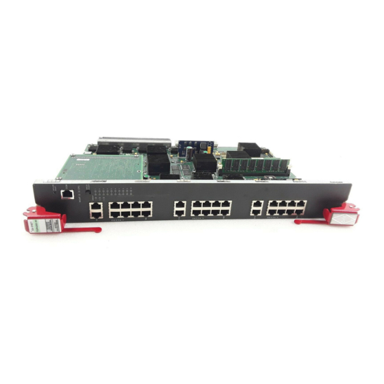
Figure 1-1 7GR4270-12 and 7GR4202-30 DFE Modules À Á Â Ã Ä Å 1 RESET switch 2 RJ45 COM (Console Port) 3 CPU LED 4 MGMT LED 5 7GR4270-12 - GROUP STATUS LEDs 7GR4202-30 GROUP SELECT switch 1-4 Introduction Ç... -
Page 23: Offline/Reset Switch
Ã Ä Å Æ Ç 7GR4280-19 - CPU LED 7KR4290-02 - MGMT LED 7GR4280-19 - GROUP SELECT switch 7KR4290-02 - XENPAK option slot 1 7GR4280-19 - GROUP STATUS LEDs 7KR4290-02 - TX (transmit) LEDs The DFE Modules À Á Â... - Page 24 7H4382-25, 7H4382-49, 7H4383-49, or 7H4385-49. 7GR4270-12 The 7GR4270‐12 DFE module has 12 front panel option ports that support 1000BASE‐X Gigabit Ethernet through optional Mini‐GBICs. For Mini‐GBIC specifications, refer to Appendix 7GR4202-30 The 7GR4202‐30 DFE module has 30, 10BASE‐T/100BASE‐TX/1000BASE‐T compliant ports through fixed front panel RJ45 connectors. 7GR4280-19 The 7GR4280‐19 DFE module has 18, 1000BASE‐X compliant, Small Form Factor Pluggable (SFP) fixed front‐panel port slots for Gigabit Ethernet connections using optional Mini‐Gigabit Interface Cards (Mini‐GBICs). The port slots enable you to install a mix‐and‐match number of SFPs to meet a need for various Gigabit Ethernet connections. For Mini‐GBIC specifications, refer to Appendix There is also a slot for an optional network expansion module (NEM). Refer to the Enterasys Networks web site for a current listing of the available NEMs. Specific installation instructions are shipped with each NEM. 7KR4290-02 The 7KR4290‐02 DFE module has 2, 10‐Gbps Ethernet port slots on the front panel that can support one or two 10‐Gbps XENPAK PHYs for high speed uplinks from the chassis DFE Ethernet switch system. With two 10‐Gbps PHYs installed in the 7KR4290‐02, a shared uplink of up to 10 Gbps can be provided from the DFE switching system to two network edge connections from a Matrix E7, N7, N5, N3 or N1 chassis to a core data center. For the XENPAK PHY specifications, refer to Appendix 1-6 Introduction A. ...
-
Page 25: Management
Management Management of the module can be either in‐band or out‐of‐band. In‐band remote management is possible using Telnet, Enterasys Networks’ NetSight application. Out‐of‐band management is provided through the RJ45 COM (Communication) port on the front panel using a VT100 terminal or a VT100 terminal emulator. Switch Configuration Using WebView Enterasys Networks’ HTTP‐based Web management application (WebView) is an intuitive web tool for simple management tasks. Switch Configuration Using CLI Commands The CLI commands enable you to perform more complete switch configuration management tasks. For CLI command set information and how to configure the module, refer to the Enterasys Matrix DFE‐Diamond/Platinum Series Configuration Guide. Secure Networks Policy Support A fundamental concept that is key to the implementation of the Enterasys Secure Networks methodology is policy‐enabled networking. This approach provides users of the network with the resources they need ‐ in a secure fashion – while at the same time denying access to applications or protocols that are deemed inappropriate based on the user’s function within the organization. By adopting such a “user‐personalized” model, it is possible for business policies to be the guidelines in establishing the technology architecture of the enterprise. Two major objectives are achieved in this way: IT services are matched appropriately with individual users; and the network itself becomes an active participant in the organization’s security strategy. The Secure Networks architecture consists of three tiers: • Classification rules make up the first or bottom tier. The rules apply to devices in the Secure Networks environment, such as switches and routers. The rules are designed to be implemented at or near the user’s point of entry to the network. Rules may be written based on criteria defined in the Layer 2, Layer 3 or Layer 4 information of the data frame. -
Page 26: Standards Compatibility
Standards Compatibility Standards Compatibility The DFE modules are fully compliant with the IEEE 802.3‐2002, 802.3ae‐2002, 802.1D‐1998, and 802.1Q‐1998 standards. The DFE modules provide IEEE 802.1D‐1998 Spanning Tree Algorithm (STA) support to enhance the overall reliability of the network and protect against “loop” conditions. LANVIEW Diagnostic LEDs LANVIEW diagnostic LEDs serve as an important troubleshooting aid by providing an easy way to observe the status of individual ports and overall network operations. For more information about LEDs, refer to Chapter 1-8 Introduction 4, Troubleshooting. -
Page 27: Link Aggregation
1000BASE-SX/LX Network XENPAK 10-Gigabit Ethernet The network installation must meet the requirements to ensure satisfactory performance of this equipment. Failure to do so will produce poor network performance. Note: The Enterasys Matrix DFE-Diamond/Platinum Series Configuration Guide and the Cabling Guide referred to in the following sections can be found on the Enterasys Networks World Wide Web site: Refer to Link Aggregation Link Aggregation is a method of grouping multiple physical ports on a network device into one ... -
Page 28: Module Placement In A Matrix E7 Chassis
Module Placement in a Matrix E7 Chassis Module Placement in a Matrix E7 Chassis If you want to mix 6x1xxx, 6x2xxx, 6x3xxx, and 7H43xx‐xx series modules in the same Matrix E7 chassis, it is necessary to have a DFE bridging module such as the 7H4382‐25, 7H4382‐49, 7H4383‐49, or 7H4385‐49 installed and to also follow the module placement rules described in “Installing Module into Matrix to some or all modules in the chassis. 10BASE-T Network When connecting a 10BASE‐T segment to any of the fixed front panel ports of the 7GR4202‐30, ensure that the network meets the Ethernet network requirements of the IEEE 802.3‐2002 standard for 10BASE‐T. Refer to the Cabling Guide for details. Note: If a port is to operate at 100 Mbps, Category 5 cabling must be used. Category 3 cabling does not meet 100 Mbps specifications. -
Page 29: Xenpak 10-Gigabit Ethernet
XENPAK 10-Gigabit Ethernet There are two optional 10‐Gigabit interface port slots on the 7KR4290‐02 that can support various optional XENPAK 10‐Gigabit Ethernet (10 GbE) standard type fiber‐optic modules. As of the printing of this guide, the 10GBASE‐LR, ‐ER, ‐LX4, and ‐SR are available. Table 2‐1 provides the cable type, maximum length, and connector type according to each version of XENPAK. For complete specifications, refer to “10GBASE XENPAK PHY Specifications” on page A‐6. Table 2-1 Recommended Cable Types and Specifications XENPAK PHY 10GBASE-LR 10GBASE-ER 10GBASE-LX4 10GBASE-SR 1. The 10GBASE-ER XENPAK requires a minimum of 5 dB attenuation or a cable length of about 10 km. The uplinks have one fiber‐optic interface with an SC connector. Depending on the XENPAK and ... - Page 30 XENPAK 10-Gigabit Ethernet 2-4 Network Requirements...
-
Page 31: Installation
Electrical Hazard: Only qualified personnel should perform installation procedures. Riesgo Electrico: Solamente personal calificado debe realizar procedimientos de instalacion. Elektrischer Gefahrenhinweis: Installationen sollten nur durch ausgebildetes und qualifiziertes Personal vorgenommen werden. Read the Release Notes shipped with the DFE module to check for any exceptions to the supported features and operation documented in this guide. -
Page 32: Required Tools
Note: If you are installing a NEM 7G-6MGBIC-B or 7K-2XFP-6MGBIC module to take advantage of additional flow capacity found in these NEM cards. 3-2 Installation 3‐1. “Backplane Connections and Installation Enterasys Networks recommends that you install either the , Quantity... -
Page 33: Installing Optional Mini-Gbics
Installing Optional Mini-GBICs This section describes how to install a Mini‐GBIC in any of the 7GR4270‐12 front panel ports (1‐12) or the 7GR4280‐19 front panel ports (1‐18) or in an optional NEM. For a list of supported Mini‐GBICs and their specifications, refer to “Mini‐GBIC Input/Output Specifications” on page A‐3. Warning: Fiber-optic Mini-GBICs use Class 1 lasers. Do not use optical instruments to view the laser output. The use of optical instruments to view laser output increases eye hazard. When viewing the output optical port, power must be removed from the network adapter. Advertencia: Los Mini-GBICS de fibra optica usan lasers de clase 1. -
Page 34: Mini-Gbic With Mt-Rj Connector
Installing Optional Mini-GBICs Figure 3-1 Mini-GBIC with MT-RJ Connector 1 Mini-GBIC (MGBIC-MT01) 2 Mini-GBIC top side 3 7-Pin edge connector (insertion side) Figure 3-2 Mini-GBIC with LC Connector 1 Mini-GBIC (MGBIC-LC01 or MGBIC-LC09) 2 Mini-GBIC top sid 3 7-Pin edge connector (insertion side) 3-4 Installation 4 Port slot 5 Mini-GBIC... -
Page 35: Mini-Gbic With Rj45 Connector
Figure 3-3 Mini-GBIC with RJ45 Connector Ä 1 Mini-GBIC (MGBIC-02) 2 Mini-GBIC, top side 3 7-Pin edge connector (insertion side) Removing the Mini-GBIC To remove a Mini‐GBIC from a port slot, proceed as follows: Caution: Do NOT remove a Mini-GBIC from a slot without releasing the locking tab located under the front bottom end of the Mini-GBIC The Mini-GBIC and its host device are sensitive to static discharges. -
Page 36: Installing An Optional Xenpak Module
Installing an Optional XENPAK Module Installing an Optional XENPAK Module This section describes how to install a XENPAK module into the 7KR4290‐02 DFE module. For the XENPAK specifications, refer to Appendix Caution: Carefully follow the instructions in this manual to avoid damaging the XENPAK module and 7KR4290-02. The XENPAK module and 7KR4290-02 strap and observe all static precautions during this procedure. Failure to do so could result in damage to the XENPAK module and 7KR4290-02. -
Page 37: Removing A Xenpak Module
Figure 3-4 XENPAK Module Installation 1 XENPAK module (10GBASE-LR is shown) 2 XENPAK module, Top Side 3 Edge connector (insertion side) Removing a XENPAK Module Caution: The XENPAK module and 7KR4290-02 are sensitive to static discharges. Use an antistatic wrist strap and observe all static precautions during this procedure. Failure to do so can result in damage to the XENPAK module and 7KR4290-02. -
Page 38: Backplane Connections And Installation Rules
The following sections describe the FTM1 and FTM2 backplane connections, and the hardware configuration rules when installing first (6x1xx), second (6x2xx), third (6x3xx), and fourth (7xxxxx) generation modules into the same Matrix E7 chassis. FTM1 and FTM2 Connectivity The Matrix E7 (6C107) chassis has backplanes referred to as FTM1 and FTM2. The 7xxxxx DFE modules use FTM2 for high speed communication to each other and operate as one switching unit with a single IP address. The traffic through these modules does not connect to FTM1 except through an FTM bridging module such as the 7H4382‐25, 7H4382‐49, 7H4383‐49, or the 7H4385‐49. The 7H4382‐49 has a connection to both FTM1 and FTM2 backplanes, which enables the 7H4382‐49 to switch frames between the two backplanes and all modules in the 6C107 chassis. However, the older first (6x1xx), second (6x2xx), and third (6x3xx) generation modules are still managed using their own Local Management and are not subject to management by the DFE module management entity. The Matrix N1 (7C111), Matrix N3 (7C103) and Matrix N7 (7C107) chassis have only FTM2 connections and support only DFE modules. The Matrix N5 (7C105‐P) has FTM2 connections and also supports PoE‐compliant DFE modules. Module Placement and Rules Depending on the modules being installed in the Matrix E7 chassis and to help ensure proper operation, consider the following examples and rules for module placement in the chassis. Figure 3‐5 shows five examples of chassis module placement. These examples are described below ... - Page 39 Example 1 (Figure 3-5, A) Shows the chassis fully populated with DFE modules (7xxxxx). These modules communicate with each other via the FTM2 chassis backplane and act as a single switching entity with one IP address. The DFE modules are configured using a Command Line Interface set of commands. Rule: DFE modules can be installed in any available chassis slot in the Matrix E7 chassis. Example 2 (Figure 3-5, B) Shows the chassis fully populated with third generation modules (6x3xx). These modules can also be installed in any available chassis slot in the Matrix E7 chassis, but operate as individual modules with separate IP addresses. Each module is configured using Local Management. Rule: The 6x3xx modules can be installed in any available chassis slot in the Matrix E7 chassis. Example 3 (Figure 3-5, C) Shows chassis slots 1 through 5 populated with first and second generation modules (6x1xx and 6x2xx). If a 6x1xx or 6x2xx series module is installed in slot 6 or 7, it will operate in standalone mode (no backplane connectivity). Like the 6x3xx modules, the 6x1xx and 6x2xx modules operate as individual modules with separate IP addresses, and each one is configured using Local Management. Rule: The 6x1xx and 6x2xx modules can communicate with each other when they are installed in chassis slots 1 through 5 in the Matrix E7 chassis. If installed in slot 6 or 7, they operate in standalone mode. Example 4 (Figure 3-5, D) Shows chassis slots 1 through 5 populated with a mix of 6x1xx, 6x2xx, and 6x3xx modules and only third generation modules in slots 6 and 7. In this module arrangement, the 6x3xx module provides a proxy bridge, which enables the 6x1xx and 6x2xx modules to communicate with 6x3xx modules in slot 6 or 7. If more than one 6x3xx module is installed in slots 1 to 5, the module in the lowest numbered slot performs the proxy ...
-
Page 40: Installing Module Into Matrix E7 Or N7 Chassis
Installing Module into Matrix E7 or N7 Chassis Example 5 (Figure Shows chassis slots 1 and 5 populated with 6x1xx, 6x2xx modules, respectively; slots 2 through 4 with DFE modules, but not a bridging module (such as the 7H4382‐25, 7H4382‐49, 7H4383‐49, or 7H4385‐49); and slots 6 and 7 with 6x3xx modules. In this module arrangement, the 6x1xx and 6x2xx modules in slots 1 and 5 can only communicate with each other, because there is no 6x3xx module in one of the first five slots to serve as the proxy bridge to communicate with the 6x3xx modules in slots 6 and 7. The 7x4xxx DFE modules in slots 2, 3, and 4 will operate under one IP address. Since there is no bridging module, the DFE modules will not communicate with any other modules in the chassis. Rule: In this example, there must be at least one 6x3xx series module, and a 7H4382‐25, 7H4382‐49, 7H4383‐49, or 7H4385‐49 bridging module in slots 1 through 5 to enable communications between all generations of modules in the chassis. Example 6 (Figure The module arrangement in this example is similar to the one shown in Figure described in Example 5. The only difference is that a 7H4382‐49 bridging module is installed in slot 2, enabling all modules to communicate with each other. Rule: In this example, the 7H4382‐49 serves as both the FTM1‐to‐FTM2 bridge and the five‐to‐ seven slot proxy bridge. The 6x3xx does not serve as a proxy bridge in this configuration because the 7H4382‐49 is in a slot with a lower number. You can use the 7H4382‐25, 7H4382‐49, 7H4383‐49, or 7H4385‐49 as a bridging module depending on the need. Installing Module into Matrix E7 or N7 Chassis Caution: Failure to observe static safety precautions could cause damage to the module. -
Page 41: Installation
Remove the module from the plastic bag. (Save the bag in the event the module must be reshipped.) Observe all precautions to prevent damage from Electrostatic Discharge (ESD). Examine the module for damage. If any damage exists, DO NOT install the module. Immediately contact Enterasys Networks. Refer to “Getting Help” on page xv. Installation To install the module, refer to Figure Caution: To prevent damaging the backplane connectors in the following step, take care that the module slides in straight and properly engages the backplane connectors. Ensure that the top lever lines up with the desired slot number located on the front panel of the chassis. -
Page 42: Installing Module Into Matrix N3, N1, Or N5 Chassis
Installing Module into Matrix N3, N1, or N5 Chassis Figure 3-6 Installing Module into Matrix E7 or N7 Chassis (Matrix E7 shown) 1 Card guides 2 Slot number 6 (Left-most slot is 1) 3 Module card 4 Metal back panel 5 Upper/lower locking tabs (in proper open position) 6 Upper/lower locking tab (in closed position) Installing Module into Matrix N3, N1, or N5 Chassis... -
Page 43: Connecting To The Network
Link Aggregation to operate properly. Before connecting the cables, refer to the Enterasys Matrix DFE-Diamond/ Platinum Series Configuration Guide for the configuration information. For details on how to obtain manuals, refer to the the installation procedure described in “Installing Module into ... -
Page 44: Connecting Utp Cables To The 7Gr4202-30
Connecting to the Network Connecting UTP Cables to the 7GR4202-30 The fixed RJ45 front panel connections of the 7GR4202‐30 front panel are 10/100/1000 Mbps ports. The ports have internal crossovers and also support automatic‐polarity sensing when configured for automatic‐negotiation. If automatic‐negotiation is not activated on a port, use a straight‐through cable when connecting a workstation to the port. When connecting a networking device to the port, such as a bridge, repeater, or router, use a crossover cable. If a port is set for auto‐negotiation, automatic‐polarity sensing is also activated. Automatic‐ polarity sensing eliminates the need for a crossover cable, regardless if the connection is to another network device or a workstation. Note: All RJ45 front panel ports on the 7GR4202-30 support Category 5 Unshielded Twisted Pair (UTP) cabling with an impedance between 85 and 111 ohms. Category 3 cable may be used if the connection is going to be used only for 10 Mbps. -
Page 45: Crossover 4-Wire Cable Rj45 Pinouts, Connections Between Hub Devices
Verify that a link exists by checking that the port RX (Receive) LED is ON (flashing amber, blinking green, or solid green). If the RX LED is OFF and the TX (Transmit) LED is not blinking amber, perform the following steps until it is on: To view the receive and transmit activity on a group of segments, press the GROUP SELECT button (see Figure time the GROUP SELECT button is pressed, the GROUP LED lights up in sequence, indicating which Group is selected. The receive and transmit activity for that group of segments is then indicated by the RX and TX LEDs for each segment. b. Verify that the cabling being used is Category 5 UTP with an impedance between 85 and 111 ohms. If the port is to operate at 100 Mbps, category 5 cabling must be used. Verify that the device at the other end of the twisted pair segment is on and properly connected to the segment. d. Verify that the RJ45 connectors on the twisted pair segment have the proper pinouts and check the cable for continuity. Typically, a crossover cable is used between hub devices. A straight‐through cable is used to connect between switches or hub devices and an end user (computer). Refer to Figure 3‐9 and Figure to Figure 3‐11 and Figure Figure 3-9 Crossover 4-Wire Cable RJ45 Pinouts, Connections Between Hub Devices À Ã RJ45 device port Other device port Figure 3-10 Straight-Through 4-Wire Cable RJ45 Pinouts, Connections... -
Page 46: Eight-Wire Crossover Cable Rj45 Pinouts, Connections Between Hub Devices
2 Other device port Figure 3-12 Eight-Wire Straight-Through Cable RJ45 Pinouts, Connections Between Switches and End User Devices 1 RJ45 device port 2 Other device port Ensure that the twisted pair connection meets the dB loss and cable specifications outlined in the Cabling Guide. Refer to “Related Documents” in About This Guide for information on obtaining this document. If a link is not established, contact Enterasys Networks. Refer to “Getting Help” on page xv for details. Repeat steps 1 through 3 above, until all connections have been made. 3-16 Installation À Â 3 RJ45-to-RJ45 crossover cable À Â... -
Page 47: Connecting Fiber-Optic Cables To Mini-Gbics
Connecting Fiber-Optic Cables to Mini-GBICs This section provides the procedure for connecting 1‐Gigabit Ethernet fiber‐optic segments from the network or other devices to Mini‐GBIC MT‐RJ or LC port connectors installed in the 7GR4270‐12 or 7GR4280‐19 DFE module or optional NEM. Each fiber‐optic link consists of two fiber‐optic strands within the cable: Transmit (TX) and Receive (RX) The transmit strand from a module port connects to the receive port of a fiber‐optic Gigabit Ethernet device at the other end of the segment. The receive strand of the applicable MT‐RJ port on the module connects to the transmit port of the fiber‐optic Gigabit Ethernet device (shown in Figure 3‐13) or LC cable connector (shown in Figure The following procedure describes how to connect an MT‐RJ cable (Figure Mini‐GBIC port connector. This procedure also applies to an LC cable connector shown in (Figure 3‐14). Refer to Figure Remove the protective covers (not shown) from the MT‐RJ fiber‐optic port on the Mini‐GBIC and from the connectors on each end of the cable. Note: Leave the protective covers in place when the connectors are not in use to prevent contamination. Caution: Do not touch the ends of the fiber-optic strands, and do not let the ends come in contact with dust, dirt, or other contaminants. -
Page 48: Cable Connection To Mt-Rj Fiber-Optic Connectors
Connecting to the Network Figure 3-13 Cable Connection to MT-RJ Fiber-Optic Connectors 1 Installed Mini-GBIC MT-RJ connecto 2 MT-RJ cable connector 3 Release tab 3-18 Installation 4 Receive LED (RX) 5 Transmit LED (TX) -
Page 49: Cable Connection To Lc Fiber-Optic Connectors
2 LC cable connector 3 Release tab Verify that a link exists by checking that the port RX LED is on (flashing amber, blinking green, or solid green). If the RX LED is off, perform the following steps until it is on: Verify that the device at the other end of the segment is ON and connected to the segment. b. If there are separate fiber‐optic connections on the other device, check the crossover of the cables. Swap the cable connections if necessary. Check that the fiber‐optic connection meets the dB loss and cable specifications outlined in the Cabling Guide for multimode fiber‐optic cabling. To obtain this document, refer to “Related Documents” in About This Guide. If a link has not been established, refer to Chapter problem persists, refer to “Getting Help” on page xv for details on contacting Enterasys Networks for support. Repeat steps 1 through 3, above, until all connections have been made. Connecting to the Network 7GR4270-12 7GR4270-12 4 Receive LED (RX) 5 Transmit LED (TX) 4 for LED troubleshooting details. If a Matrix DFE-Diamond Series Installation Guide 3-19... -
Page 50: Connecting To Com Port For Local Management
Connecting to COM Port for Local Management Plug the other end of the cable into the appropriate port on the other device. Some cables may be terminated at the other end with two separate connectors, one for each fiber‐optic strand. In this case, ensure that the transmit fiber‐optic strand is connected to the receive port and the receive fiber‐optic strand to the transmit port. Connecting to COM Port for Local Management This section describes how to install a UTP straight‐through cable with RJ45 connectors and optional adapters to connect a PC, a VT series terminal, or a modem to an Enterasys Networks module to access Local Management. This section also provides the pinout assignments of the adapters. What Is Needed The following is a list of the user‐supplied parts that may be needed depending on the connection: • RJ45‐to‐DB9 female adapter • UTP straight‐through cable terminated at both ends with RJ45 connectors • RJ45‐to‐DB25 female adapter • RJ45‐to‐DB25 male adapter Using a UTP straight‐through cable and an RJ45‐to‐DB9 adapter, you can connect products equipped with an RJ45 COM port to an IBM or compatible PC running a VT series emulation software package. Using a UTP straight‐through cable and an RJ45‐to‐DB25 female adapter, you can connect products equipped with an RJ45 COM port to a VT series terminal or VT type terminals running ... -
Page 51: Connecting To A Vt Series Terminal
Figure 3-15 Connecting an IBM PC or Compatible 1 UTP straight-through cable 2 RJ45 COM port Connecting to a VT Series Terminal To connect a VT Series terminal to an Enterasys use a UTP straight‐through cable with RJ45 connectors and an RJ45‐to‐DB25 female adapter, and proceed as follows: Connect the RJ45 connector at one end of the UTP straight‐through cable to the COM port on the Enterasys Networks module. Plug the RJ45 connector at the other end of the UTP straight‐through cable into the RJ45‐to‐ DB25 female adapter. Connect the RJ45‐to‐DB25 adapter to the port labeled COMM on the VT terminal. Turn on the terminal to access the Setup Directory and set the following parameters: Parameter Mode Transmit Bits Parity Stop Bit When these parameters are set, the Local Management password screen will display. Refer to the ... -
Page 52: Connecting To A Modem
Connecting to COM Port for Local Management Figure 3-16 Connecting a VT Series Terminal 1 UTP straight-through 2 RJ45 COM port Connecting to a Modem To connect a modem to an Enterasys straight‐through cable with RJ45 connectors and an RJ45‐to‐DB25 male adapter, and proceed as follows: Connect the RJ45 connector at one end of the UTP straight‐through cable to the COM port of the module. Plug the RJ45 connector at the other end of the UTP straight‐through cable into the RJ45‐to‐ DB25 modem adapter. Connect the RJ45‐to‐DB25 adapter to the communications port on the modem. Turn on the modem. With a PC connected to a remote modem, you can configure the switch remotely. To accomplish this, you must configure your PC VT emulation package with the following parameters: Parameter Mode... -
Page 53: Adapter Wiring And Signal Assignments
Figure 3-17 Connecting to a Modem 1 UTP straight-through 2 RJ45 COM port 3 RJ45-to-DB25 modem adapter Adapter Wiring and Signal Assignments RJ45 Conductor Blue Green Orange Yellow cable with RJ45 connectors 4 Local modem 5 Remote modem 6 PC COM Port Adapter Wiring and Signal Diagram Matrix DFE-Diamond Series Installation Guide 3-23 Connecting to COM Port for Local Management... -
Page 54: Completing The Installation
Completing the Installation RJ45 RJ45 Completing the Installation Completing the DFE module installation depends on if the module is being installed in: • a new DFE module system (refer to “Completing the Installation of a New System” on page 3‐25), or • an established, operating DFE module system (refer to “Completing the Installation of a DFE Module in an Existing System” on page 3‐26). 3-24 Installation VT Series Port Adapter Wiring and Signal Diagram DB25 Conductor Blue Yellow Green Orange Modem Port Adapter Wiring and Signal Diagram DB25 Conductor Blue... -
Page 55: Completing The Installation Of A New System
Only access; rw for Read-Write access; and admin for super-user access to all modifiable parameters. The default password is set to blank (carriage return). For information on changing these default passwords, refer to Chapter 3 in the Enterasys Matrix DFE-Diamond/Platinum Series Configuration Guide Start the Command Line Interface (CLI) from the module’s local console port as follows:... -
Page 56: Matrix Dfe Startup Screen Example (N7 Chassis)
For information on the set password and set system login commands, refer to the Enterasys Matrix DFE-Diamond/Platinum Series Configuration Guide... - Page 57 Completing the Installation The DFE module is now ready to be configured. For information about setting the IP address and configuring Telnet settings for remote access to DFE management, refer to the Enterasys Matrix DFE‐Diamond/Platinum Series Configuration Guide. The CLI commands enable you to initially set up and perform more involved management configurations. The Enterasys Matrix DFE‐Diamond/Platinum Series Configuration Guide is available online at: http://www.enterasys.com/support/manuals If you require assistance, contact Enterasys Networks using one of the methods described in “Getting Help” on page xv. Matrix DFE-Diamond Series Installation Guide 3-27...
- Page 58 Completing the Installation 3-28 Installation...
-
Page 59: Chapter 4: Troubleshooting
This chapter provides information concerning the following: For information about... Using LANVIEW Troubleshooting Checklist Overview of DFE Module Shutdown Procedure Recommended Shutdown Procedure Last Resort Shutdown Procedure Using LANVIEW The modules use a built‐in visual diagnostic and status monitoring system called LANVIEW. The LANVIEW LEDs (Figure network problems. About the Management (MGMT) LED The MGMT LED (shown in Figure Module to control the management functions for all DFE modules in the chassis. The Management Module handles all IP requests to the chassis IP address, such as PING, Telnet, SNMP, or HTTP. The Management Module also handles the CLI configuration sessions via the console port. So, when you plug into a DFE module COM port to configure a DFE module in the chassis, it is handled by the Management Module regardless of the DFE module COM port that you use. Viewing the Receive and Transmit Activity On the 7GR4270‐12 , 7GR4202‐30, and 7GR4280‐19 DFE modules, you can view the receive and ... -
Page 60: Lanview Leds
Using LANVIEW Figure 4-1 LANVIEW LEDs 1 MGMT LED Table 4‐1 describes the LED indications and provides recommended actions as appropriate. Note: The terms flashing, blinking, and solid used in Flashing indicates an LED is flashing randomly. Blinking indicates an LED is flashing at a steady rate (approximately 50% on, 50% off). Solid indicates a steady LED light. - Page 61 None. Contact Enterasys Networks for technical support. If it is known that the port should be active and is not, contact Enterasys Networks for technical support. None. None, unless there is a high rate of activity. In this case, check for network configuration problems or a defective device.
-
Page 62: Troubleshooting Checklist
Refer to the Enterasys Matrix DFE-Diamond/ Platinum Series Configuration Guide for the IP address assignment procedure. Port is disabled. Enable port. Refer to the Enterasys Matrix DFE- Diamond/Platinum Series Configuration Guide for instructions to enable/disable ports. Host Port policy and/or... -
Page 63: Overview Of Dfe Module Shutdown Procedure
4‐2. There are two procedures to shut down a DFE module. Overview of DFE Module Shutdown Procedure Recommended Action Reenter the lost parameters as necessary. Refer to the Enterasys Matrix DFE-Diamond/Platinum Series Configuration Guide for the instructions to configure the device. If the problem continues, contact Enterasys Networks for technical support. -
Page 64: Recommended Shutdown Procedure
Recommended Shutdown Procedure Figure 4-2 OFFLINE/RESET Switch 1 OFFLINE/RESET switch Recommended Shutdown Procedure Caution: Do not pull any DFE-Diamond module out of an operating chassis before it has completed its shutdown routine. Precaución: No retire los módulos DFE-Diamond del chasis en funcionamiento hasta que no se haya terminado con la rutina de apagado. -
Page 65: Last Resort Shutdown Procedure
Precaución: No se recomienda utilizar este método para apagar los módulos DFE-Diamond. Recurra a él sólo como último recurso, puesto que interrumpe todos los procesos del módulo en funcionamiento, lo que podría resultar pérdidas de frames. To reset a DFE module without it performing an orderly shutdown routine, press and hold the OFFLINE/RESET switch for approximately 6 seconds. Pulling any DFE module out of the chassis before it has been shut down is not recommended. The only safe time to pull a module out of the chassis is after the completion of a shutdown and the management LED is flashing amber/off. - Page 66 Last Resort Shutdown Procedure 4-8 Troubleshooting...
-
Page 67: A-1 Specifications
This appendix provides information about the following: For information about... DFE Module Specifications Mini-GBIC Input/Output Specifications Gigabit Ethernet Specifications 10GBASE XENPAK PHY Specifications COM Port Pinout Assignments Regulatory Compliance Enterasys Networks reserves the right to change the specifications at any time without notice. DFE Module Specifications Table A‐1 provides the I/O ports, processors and memory, physical, and environmental module specifications for the 7GR4270‐12, 7GR4202‐30, 7GR4280‐19, and 7KR4290‐02 DFE modules. Unless noted differently, the specifications apply to all four DFE modules. Table A-1 Specifications Item 7GR4270-12 Ports Ports 1 through 12... - Page 68 Gross: 5.0 kg (11.0 lb) (shipping carton containing one module) Net: 3.86 kg (8.5 lb) (one module without packaging) Refer to the MTBF web site at this URL: http://www.enterasys.com/support/mtbf/ 5°C to 40°C (41°F to 104°F) -30°C to 73°C (-22°F to 164°F) 5% to 90% (non-condensing)
-
Page 69: Mini-Gbic Input/Output Specifications
Mini-GBIC Input/Output Specifications The Mini‐Gigabit Ethernet Card (Mini‐GBIC) port interface slots can accept 1000BASE‐SX short wavelength or 1000BASE‐LX long wavelength fiber‐optic Mini‐GBICs (see Table optional Mini‐GBICs are hot swappable. Table A-2 Mini-GBIC Input/Output Port Specifications Item MGBIC-LC01 MGBIC-LC03 MGBIC-LC09 MGBIC-MT01 MGBIC-08 MGBIC-02 Gigabit Ethernet Specifications The following specifications for the Mini‐GBICs (shown in Table A‐3 through Table exceed the IEEE 802.3z‐1998 standard. MGBIC-LC01/MGBIC-MT01 Specifications (1000BASE-SX) Table A-3 MGBIC-LC01 / MGBIC-MT01 Optical Specifications Item Transmit Power (minimum) Receive Sensitivity Link Power Budget Table A-4 MGBIC-LC01 / MGBIC-MT01 Operating Range Item... -
Page 70: Mgbic-Lc03 Specifications (1000Base-Sx
Gigabit Ethernet Specifications MGBIC-LC03 Specifications (1000BASE-SX) Table A-5 MGBIC-LC03 Optical Specifications Item Transmit Power (minimum) Transmit Power (maximum) Receive Sensitivity Link Power Budget 1. The maximum drive distance (up to 2 km) depends on the quality of the installed multimode fiber-optic cable segment. -
Page 71: Mgbic-08 Specifications (1000Base-Elx
MGBIC-08 Specifications (1000BASE-ELX) Table A-9 MGBIC-08 Optical Specifications Item Transmit Power (minimum) Receive Sensitivity Maximum Input Power Link Power Budget (Full Duplex Only) 1. The maximum drive distance (up to 70 km) depends on the quality of the installed single-mode fiber-optic cable segment. -
Page 72: 10Gbase Xenpak Phy Specifications
10GBASE XENPAK PHY Specifications 10GBASE XENPAK PHY Specifications At the time of printing of this manual, there are four 10GBASE XENPAK modules available. Tables A‐12 through A‐14 provide the specifications for each XENPAK module. Table A-12 XENPAK Port, Physical, and Environmental Specifications Item Port One Port Physical Dimensions Approximate Weight Environmental Operating Temperature Storage Temperature Operating Relative Humidity Table A-13 provides you with the input/output specifications for each version of XENPAK. Table A-13 XENPAK Fiber-Optic Specifications XENPAK PHY 10GBASE-LR... -
Page 73: Com Port Pinout Assignments
COM Port Pinout Assignments The COM port is a serial communications port for local access to Local Management. Refer to Table A‐15 for the COM port pin assignments. Table A-15 COM Port Pin Assignments Signal Name Transmit Data (XMT) Data Carrier Detect (DCD) Data Set Ready (DSR) Receive Data (RCV) Signal Ground (GND) Data Terminal Ready (DTR) Request to Send (RTS) Clear to Send (CTS) Regulatory Compliance The 7GR4270‐12, 7GR4202‐30, 7GR4280‐19, and 7KR4290‐02 meet the safety and electromagnetic ... - Page 74 Regulatory Compliance A-8 Specifications...
-
Page 75: Appendix B: Mode Switch Settings And Installing Options
Caution: Read the appropriate sections to be fully aware of the consequences when changing switch settings. Only qualified personnel should change switch settings. Precaución: Si desea modificar la configuración del interruptor, lea las secciones correspondientes para saber cuál será el resultado de hacerlo. -
Page 76: Mode Switch Location On 7Gr4270-12
• Switch 8 – Clear Admin Password. Changing the position of this switch clears the admin password, and restores the factory default password on the next power‐up of the module. Once the module resets, you can either use the factory default settings or reenter your own password. Note: Do not change the position of Switch 8 unless it is necessary to reset the admin password to its factory default setting. Figure B-1 Mode Switch Location on 7GR4270-12 1 Mode switch bank (7GR4270-12) -
Page 77: Memory Locations And Replacement Procedures
Mode Switch Location on the 7KR4290-02 1 Mode switch bank (7KR4290-02) Memory Locations and Replacement Procedures In the event that the Dual in Line Memory Module (DIMM) or DRAM Single In‐line Memory Module (SIMM) needs to be replaced, the following sections describe how to access, locate, and replace these memory modules. If you have questions concerning the replacement of the memory modules, refer to “Getting Help” on page xv for details on how to contact Enterasys Networks. Location of DIMM and DRAM SIMM Memory Modules Figure B‐5 through Figure board. The 7GR4270‐12 is shown in Figure the 7GR4202‐30. Memory Locations and Replacement Procedures B‐7 show the locations of the DIMM and DRAM SIMM on each main ... -
Page 78: Dimm And Dram Simm Locations For 7Gr4270-12 And 7Gr4202-30
DIMM and DRAM SIMM Locations for 7GR4270-12 and 7GR4202-30 1 DRAM SIMM Figure B-6 DIMM and DRAM SIMM Locations for 7GR4280-19 1 Flash DIMM B-4 Mode Switch Settings and Installing Options 2 Flash DIMM 3 Main PC board (7GR4270-12 is shown) 2 DRAM SIMM ➂... -
Page 79: Dimm And Dram Simm Locations For 7Kr4290-02
Figure B-7 DIMM and DRAM SIMM Locations for 7KR4290-02 1 DRAM SIMM DRAM SIMM Replacement Procedure Note: To access and remove a DIMM or DRAM SIMM memory module, you may need to remove the optional network expansion module (NEM), if one is installed in your DFE-Diamond module. To remove the NEM, refer to the instructions in (NEM)”... -
Page 80: Removing The Existing Dram Simm
Precaución: Al trabajar con equipos electrónicos sensibles, tome todas las precauciones de seguridad para evitar descargas de electricidad estática. To install a DRAM SIMM, refer to Figure Push the connector arms away from the DRAM SIMM enough to insert the DRAM SIMM into the connector contacts. Insert the DRAM SIMM straight down between the connector contacts enough for the tabs on the connector arms to align with the two DRAM SIMM alignment notches. Push the DRAM SIMM down into the connector contacts. Then rotate the two connector arms toward the DRAM SIMM to lock it into place. B-6 Mode Switch Settings and Installing Options Á À Â DRAM SIMM B‐9 and proceed as follows: À Connector contacts... -
Page 81: Dimm Replacement Procedure
Figure B-9 Installing the DRAM SIMM DRAM SIMM Connector arms DRAM SIMM DIMM Replacement Procedure Note: To access and remove a DIMM or DRAM SIMM memory module, you may need to remove the optional network expansion module (NEM), if one is installed in your DFE-Diamond module. To remove the NEM, refer to the instructions in (NEM)”... -
Page 82: Installing The Dimm
Insert the DIMM down between the connector fingers. Pivot the DIMM downward so the tabs on the connector arms align with the two DIMM alignment notches. With the two connector arms spread outward, push the DIMM down between the connector arms. Then release the two connector arms to lock the DIMM into place. If necessary, reinstall the NEM. Refer to the installation instructions shipped with the NEM for details. Figure B-11 Installing the DIMM 1 DIMM 2 Connector fingers B-8 Mode Switch Settings and Installing Options À Á Â 2 DIMM B‐11 and proceed as follows: Ã À Â Á 3 Connector arms 4 DIMM alignment notches (2) À... -
Page 83: Removing The Optional Network Expansion Module (Nem
Removing the Optional Network Expansion Module (NEM) Refer to Figure B‐12 and proceed as follows: Attach the antistatic wrist strap (refer to the instructions on the antistatic wrist strap package). Figure B-12 Removing the Optional Network Expansion Module 1 Coverplate screws (2) 2 NEM 3 DFE module front panel Remove and save the two coverplate screws fastening the NEM to the DFE module front panel. Remove and save the screw fastening the NEM to the standoff on the main PC board. The screws removed in steps 2 and 3 are used later to reinstall the NEM. Lift and remove the NEM off the two main PC board connectors. Now you have access to the DRAM SIMM and DIMM. To replace the DRAM SIMM, refer to “DRAM SIMM Replacement Procedure” on page B‐5. To replace the DIMM, refer to “Removing the DIMM” on page B‐7. Reinstall the NEM. Refer to the installation instructions shipped with the NEM for details. Memory Locations and Replacement Procedures 4 Screw 5 Main PC board 6 Main board connectors... - Page 84 Memory Locations and Replacement Procedures B-10 Mode Switch Settings and Installing Options...
- Page 85 Index MGBIC-08 specifications for MGBIC-LC01/MGBIC-MT01 specifications for MGBIC-LC03 specifications for MGBIC-LC09 specifications for Mini-GBIC installation of removal of specifications for Mode Switch setting of Module coverplate removal of Module features 7GR4202-30 7GR4270-12 7GR4280-19 7KR4290-02 installing Network connecting to 3-13 Network expansion module...
- Page 86 Specifications, MGBIC-LC09 operating range optical Specifications, MGBIC-MT01 operating range optical Standards compatibility Support Technical support contatacting Enterasys for Transmit LEDs viewing of Troubleshooting checklist for Unpacking the module User Personalized Networks (UPN) See Secure Networks Policy Support. Viewing Receive and Transmit Activity...
Need help?
Do you have a question about the Matrix 7GR4202-30 and is the answer not in the manual?
Questions and answers