Table of Contents
Advertisement
Quick Links
Advertisement
Table of Contents

Subscribe to Our Youtube Channel
Related Manuals for Enterasys Matrix E7 6C107


Summary of Contents for Enterasys Matrix E7 6C107
- Page 1 Matrix E7 6C107 Chassis Overview and Setup Guide 9033280-03...
- Page 3 Enterasys Networks reserves the right to make changes in specifications and other information contained in this document and its web site without prior notice. The reader should in all cases consult Enterasys Networks to determine whether any such changes have been made.
-
Page 4: Industry Canada Notice
FCC NOTICE This device complies with Part 15 of the FCC rules. Operation is subject to the following two conditions: (1) this device may not cause harmful interference, and (2) this device must accept any interference received, including interference that may cause undesired operation. -
Page 5: Program License Agreement
This document is an agreement (“Agreement”) between You, the end user, and Enterasys Networks, Inc. (“Enterasys”) that sets forth your rights and obligations with respect to the Enterasys software program (“Program”) in the package. The Program may be contained in firmware, chips or other media. UTILIZING THE ENCLOSED PRODUCT, YOU ARE AGREEING TO BECOME BOUND BY THE TERMS OF THIS AGREEMENT, WHICH INCLUDES THE LICENSE AND THE LIMITATION OF WARRANTY AND DISCLAIMER OF LIABILITY. - Page 6 52.227-19 (a) through (d) of the Commercial Computer Software-Restricted Rights Clause and its successors, and (iii) in all respects is proprietary data belonging to Enterasys and/or its suppliers. For Department of Defense units, the Product is considered commercial computer software in accordance with DFARS section 227.7202-3 and its successors, and use, duplication, or disclosure by the Government is subject to restrictions set forth herein.
-
Page 7: Declaration Of Conformity
Manufacturer’s Address: European Representative Address: Conformance to Directive(s)/Product Standards: Equipment Type/Environment: Networking Equipment, for use in a Commercial Enterasys Networks, Inc. declares that the equipment packaged with this notice conforms to the above directives. 73/23/EEC 35 Industrial Way PO Box 5005 Rochester, NH 03867 Enterasys Networks Ltd. -
Page 9: Table Of Contents
Figures ...ix Tables... x ABOUT THIS GUIDE Using This Guide...xi Structure of This Guide ...xi Using the Matrix E7 6C107 Chassis Series Manual Set ...xii Document Conventions...xii INTRODUCTION Overview ... 1-1 Features ... 1-3 Getting Help ... 1-6 INSTALLATION REQUIREMENTS AND GUIDELINES Site Guidelines ... -
Page 11: Figures
Figure The Matrix E7 6C107 Chassis with Redundant Power Supplies... 1-2 6C207-1 (Rev. OF) Power Supply LEDs ... 2-3 6C207-3 Power Supply LEDs... 2-3 Fan Tray LED ... 2-4 Chassis Bottom, Rubber Feet Placement ... 3-4 Installing the Cable Management Bar ... 3-5 Shelf Installation ... -
Page 12: Tables
Tables Table Power Supply (PS) LED Status Definitions...2-4 Fan Tray LED States and Their Definitions ...2-4 Tables Page... -
Page 13: About This Guide
Welcome to the Matrix E7 6C107 Chassis Overview and Setup Guide. This guide lists the features and options of the Matrix E7 6C107 chassis and explains how to remove and reinstall its fan tray, install the cable management bar, power supplies, and interface modules. -
Page 14: Using The Matrix E7 6C107 Chassis Series Manual Set
Using the Matrix E7 6C107 Chassis Series Manual Set USING THE MATRIX E7 6C107 CHASSIS SERIES MANUAL SET Separate manuals have been developed for the interface modules that can be installed in the Matrix E7 chassis. These manuals explain how to install the modules into the Matrix E7 chassis, how to attach cable segments to the modules, and how to configure the modules using Local Management after installation is complete. -
Page 15: Introduction
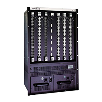
This chapter provides an overview of the Matrix E7 chassis and its features. Also covered in this chapter are the instructions on how to obtain additional help from Enterasys Networks if needed. OVERVIEW The Matrix E7 chassis design provides seven slots that can contain a variety of interface modules. - Page 16 Overview Figure 1-1 The Matrix E7 6C107 Chassis with Redundant Power Supplies...
-
Page 17: Redundant Power Supplies
FEATURES The following provides an overview of the chassis features. Matrix E7 Chassis Modules The Matrix E7 chassis has seven slots for interface modules. The Matrix E7 chassis supports all generations of Matrix and SmartSwitch 6000 modules. This provides the flexibility to configure the chassis with the maximum types of boards available to support 10/100 Ethernet and Gigabit Ethernet to WAN and ATM applications. -
Page 18: Power Supply Lanview Leds
Features 6C207-3 The 6C207-3 is a 1600-Watt power supply, which has two front-panel ac input power connectors. The type of power cords shipped with the unit is country-dependent. Each power cord must be plugged into a separately fused power circuit. NOTE: Both power cords must be connected to the 6C207-3 for it to operate, and connected to two separately fused ac power sources to handle the input power requirements. -
Page 19: Hot Swapping
Features Auto-Ranging Power Supplies The Matrix E7 chassis power supplies automatically adjust to the input voltage and frequency, which allows an input voltage of 100 to 220 Vac, and a frequency between 50 and 60 Hz. See the operating specifications in Appendix A. -
Page 20: Getting Help
Getting Help GETTING HELP For additional support related to the Matrix E7 chassis or this document, contact Enterasys Networks using one of the following methods: World Wide Web http://www.enterasys.com/ Phone (603) 332-9400 Internet mail support@enterasys.com ftp://ftp.enterasys.com Login anonymous Password your email address To send comments or suggestions concerning this document, contact the Technical Writing Department via the following email address: TechWriting@enterasys.com... -
Page 21: Installation Requirements And Guidelines
Installation Requirements and Guidelines This chapter describes the following: • Site guidelines that must be met before installing a Matrix E7 chassis into a rack or cabinet • Matrix E7 chassis configuration guidelines • Operating specifications for the Matrix E7 chassis enclosure and power supply modules ELECTRICAL HAZARD: Only qualified personnel should install or service this unit. -
Page 22: Configuration Guidelines
Configuration Guidelines • Ambient temperature at the installation site must be maintained between 5° and 40°C (41° to 104°F). Temperature changes must be maintained within 10°C (18°F) per hour. CONFIGURATION GUIDELINES The Matrix E7 chassis has seven slots that accept interface modules. The slots are numbered 1 to 7 beginning with the leftmost slot. -
Page 23: C207-1 (Rev. Of) Power Supply Leds
LANVIEW LEDs Figure 2-1 6C207-1 (Rev. OF) Power Supply LEDs Figure 2-2 6C207-3 Power Supply LEDs... -
Page 24: Fan Tray Led
LANVIEW LEDs Table 2-1 Power Supply (PS) LED Status Definitions Condition Out of chassis 2.3.2 Fan Tray LED Refer to Figure 2-3 for the location of the fan tray LED. the fan tray LED. Figure 2-3 Fan Tray LED Table 2-2 Fan Tray LED States and Their Definitions LED Color Status Green... -
Page 25: Matrix E7 Setup
This chapter contains instructions on setting up the Matrix E7 chassis. Equipment needed: • Phillips screwdriver • Flat blade screwdriver ELECTRICAL HAZARD: Only qualified personnel should install or service this unit. A Phillips screwdriver is needed to install the unit in a 48.26-centimeter (19-inch) equipment rack and to install the cable management bar. -
Page 26: Unpacking The Matrix E7 Chassis
2. Remove the chassis from the protective plastic bag. 3. Examine the Matrix E7 chassis carefully, checking for damage. If any damage is noted, DO NOT install the chassis. Contact Enterasys Networks immediately. 4. Remove the accessory package. 5. Remove the package containing the four rubber feet/screw assemblies. -
Page 27: Setting Up The Matrix E7 Chassis
SETTING UP THE MATRIX E7 CHASSIS The following sections describe the procedures that must be followed to complete the installation of the Matrix E7 chassis. 3.2.1 Order of Installation Once a suitable site has been chosen, the Matrix E7 chassis can be installed as a freestanding or rack-mounted unit. -
Page 28: Chassis Bottom, Rubber Feet Placement
Setting Up the Matrix E7 Chassis 3.2.2.1 Installing the Rubber Feet To install the rubber feet, proceed as follows: 1. Remove the four rubber foot/screw assemblies from their plastic bag in the shipping box. 2. Locate the four tapped holes in the bottom four corners of the chassis shown in Figure 3-1 Chassis Bottom, Rubber Feet Placement 3. -
Page 29: Installing The Cable Management Bar
3.2.2.2 Installing the Cable Management Bar With the cable management bar, cables can be attached along the bar using cable ties to ensure that the cables are not accidentally loosened or disconnected from the chassis during operation. To install the cable management bar, proceed as follows: 1. -
Page 30: Rack Mounting The Matrix E7 Chassis
Setting Up the Matrix E7 Chassis 3.2.3 Rack Mounting the Matrix E7 Chassis The Matrix E7 chassis can be mounted in a standard 48.26-centimeter (19-inch) equipment rack. To rack mount the chassis into a rack you need to • allow at least 60 centimeters (24 inches) of clearance in front of the rack for chassis installation, •... -
Page 31: Shelf Installation
Figure 3-3 Shelf Installation 3.2.3.2 Installing the Matrix E7 Chassis CAUTION: Read all installation guidelines are met. To install the Matrix E7 chassis, proceed as follows: CAUTION: To help prevent personal injury, at least two people are required to lift the chassis into the rack. -
Page 32: Rack Mounting The Matrix E7 Chassis
Setting Up the Matrix E7 Chassis 2. Use 12 screws provided with the equipment rack to secure the chassis to the rack, starting with the bottom holes and working toward the top of the chassis, as shown in Figure 3-4 Rack Mounting the Matrix E7 Chassis 3.2.3.3 Attaching the Electrostatic Discharge Wrist Strap The Electrostatic Discharge (ESD) wrist strap must be attached before handling the power... -
Page 33: Installing A Power Supply
Figure 3-5 ESD Grounding Receptacle 3.2.4 Installing a Power Supply CAUTION: Newer models of modules may require more power to operate. If the power requirement of the module population in a Matrix E7 chassis exceeds the power output of a single 6C207-1 (1200-Watt) power supply, it is not recommended to install a 6C207-1 (1200-Watt) and a 6C207-3 (1600-Watt) power supply in the same chassis. - Page 34 3. Examine the power supply carefully, checking for damage. If any damage is noted, DO NOT install the power supply. Contact Enterasys Networks immediately. 4. Slide the power supply into the slot labeled PS1 as follows: a.
-
Page 35: Installing The Power Supply Module(S)
Setting Up the Matrix E7 Chassis Figure 3-6 Installing the Power Supply Module(s) 3-11... -
Page 36: Installing Matrix E7 Interface Modules
Setting Up the Matrix E7 Chassis After completing the power supply installation, the Matrix E7 chassis is ready to be powered up. Before you power up the Matrix E7 chassis, it is recommended that you complete the installation of the interface modules in the Matrix E7 chassis. Refer to the following sections to complete the installation. -
Page 37: Installation Procedure
Observe all precautions to prevent damage from Electrostatic Discharge (ESD). 5. Examine the module for damage. If any damage exists, DO NOT install the module. Immediately contact Enterasys Networks. CAUTION: To prevent damaging the backplane connectors in the following step, take care that the module slides in straight and properly engages the backplane connectors. -
Page 38: Installing An Interface Module
Setting Up the Matrix E7 Chassis Figure 3-7 Installing an Interface Module 3-14... -
Page 39: Powering Up A Matrix E7 Chassis With Power Supplies
POWERING UP A MATRIX E7 CHASSIS WITH POWER SUPPLIES To power up a Matrix E7 chassis with ac power supplies, proceed as follows: NOTE: If two power supplies are installed, repeat the following procedure for each supply. For proper redundancy using two 6C207-1 power supplies, the power cord from each power supply must be connected to a dedicated 20-Ampere ac power circuit. -
Page 40: Connecting The 15-Amp Ac Power Cords To The 6C207-3
6C207-1. For the 6C207-3, plug each of the two power cords into separate dedicated 15 A/115 Vac receptacles. Set the 0/| Power switch on the front panel of the power supply to |. 3. Ensure that the Power LED is green. -
Page 41: Removing And Reinstalling The Fan Tray
REMOVING AND REINSTALLING THE FAN TRAY The Matrix E7 chassis is equipped at the factory with a removable fan tray that allows for easy periodic cleaning and/or replacement if a problem occurs with fan operation. A flat blade screwdriver is needed to remove and reinstall the fan tray. To remove and reinstall the fan tray, refer to Section 3.4.1 Section... -
Page 42: Removing The Fan Tray
Removing and Reinstalling the Fan Tray Figure 3-10 Removing the Fan Tray 3-18... -
Page 43: Reinstalling The Fan Tray
3.4.2 Reinstalling the Fan Tray To reinstall the fan tray, refer to 1. Locate the ESD wrist strap shipped with the Matrix E7 chassis. Attach the ESD wrist strap to your wrist and plug the cable from the ESD wrist strap into the ESD grounding receptacle at the upper right corner of the chassis. -
Page 44: Reinstalling The Fan Tray
Removing and Reinstalling the Fan Tray Figure 3-11 Reinstalling the Fan Tray Once the tray is in place, tighten the two slotted screws (see Matrix E7 chassis. 3-20 Figure 3-11) to secure the tray to the... -
Page 45: Specifications And Regulatory Compliance
Networks reserves the right to change the specifications at any time without notice. PHYSICAL SPECIFICATIONS The physical specifications for the Matrix E7 6C107 chassis, the 6C207-1 and 6C207-3 power supply modules, and the 6C407 fan tray module are as follows:... -
Page 46: Power Supply Requirements
Power Supply Requirements POWER SUPPLY REQUIREMENTS The requirements for the 6C207-1 and 6C207-3 ac power supply modules are as follows: Input Frequency: Input: (Voltage/Current): Input Power ENVIRONMENTAL REQUIREMENTS Operating Temperature: Storage Temperature: Operating Relative Humidity: REGULATORY COMPLIANCE This equipment meets the following safety and electromagnetic compatibility (EMC) requirements: Safety: Electromagnetic Compatibility (EMC):...
Need help?
Do you have a question about the Matrix E7 6C107 and is the answer not in the manual?
Questions and answers