
Related Manuals for Enterasys Matrix 7G4270-12


Summary of Contents for Enterasys Matrix 7G4270-12
- Page 1 Enterasys Matrix ® DFE-Platinum Series Hardware Installation Guide 7H4382-49 7H4383-49 7G4270-12 7G4202-30 7H4203-72 P/N 9033835-09...
- Page 3 Enterasys Networks reserves the right to make changes in specifications and other information contained in this document and its web site without prior notice. The reader should in all cases consult Enterasys Networks to determine whether any such changes have been made.
-
Page 4: Regulatory Compliance Information
Le présent appareil numérique n’émet pas de bruits radioélectriques dépassant les limites applicables aux appareils numériques de la class A prescrites dans le Règlement sur le brouillage radioélectrique édicté par le ministère des Communications du Canada. Class A ITE Notice WARNING: This is a Class A product. In a domestic environment this product may cause radio interference in which case the user may be required to take adequate measures. Clase A. Aviso de ITE ADVERTENCIA: Este es un producto de Clase A. En un ambiente doméstico este producto puede causar interferencia de radio en cuyo caso puede ser requerido tomar medidas adecuadas. Klasse A ITE Anmerkung WARNHINWEIS: Dieses Produkt zählt zur Klasse A ( Industriebereich ). In Wohnbereichen kann es hierdurch zu Funkstörungen kommen, daher sollten angemessene Vorkehrungen zum Schutz getroffen werden. Product Safety This product complies with the following: UL 60950, CSA C22.2 No. 60950, 2006/95/EC, EN 60950, IEC 60950, EN 60825, 21 CFR 1040.10. Seguridad del Producto El producto de Enterasys cumple con lo siguiente: UL 60950, CSA C22.2 No. 60950, 2006/95/EC, EN 60950, IEC 60950, EN 60825, 21 CFR 1040.10. -
Page 5: Hazardous Substances
Dieses Produkt entspricht den folgenden Richtlinien: UL 60950, CSA C22.2 No. 60950, 2006/95/EC, EN 60950, IEC 60950, EN 60825, 21 CFR 1040.10. ELECTROMAGNETIC COMPATIBILITY (EMC) This product complies with the following: 47 CFR Parts 2 and 15, CSA C108.8, 2004/108/EC, EN 55022, EN 61000‐3‐2, EN 61000‐3‐3, EN 55024, AS/NZS CISPR 22, VCCI V‐3. Compatibilidad Electromágnetica (EMC) Este producto de Enterasys cumple con lo siguiente: 47 CFR Partes 2 y 15, CSA C108.8, 2004/108/EC, EN 55022, EN 55024, EN 61000‐3‐2, EN 61000‐3‐3, AS/NZS CISPR 22, VCCI V‐3. Elektro- magnetische Kompatibilität ( EMC ) Dieses Produkt entspricht den folgenden Richtlinien: 47 CFR Parts 2 and 15, CSA C108.8, 2004/108/EC, EN 55022, EN 61000‐3‐2, EN 61000‐3‐3, EN 55024, AS/NZS CISPR 22, VCCI V‐3. This product complies with the requirements of European Directive, 2002/95/EC, Restriction of Hazardous Substances (RoHS) in Electrical and Electronic Equipment. European Waste Electrical and Electronic Equipment (WEEE) Notice In accordance with Directive 2002/96/EC of the European Parliament on waste electrical and electronic equipment (WEEE): The symbol above indicates that separate collection of electrical and electronic equipment is required and that this product was placed on the European market after August 13, 2005, the date of enforcement for Directive 2002/96/EC. - Page 6 SJ/T 11363-2006 standard. This table shows where these substances may be found in the supply chain of Enterasys’ electronic information products, as of the date of sale of the enclosed product. Note that some of the component types listed above may or may not be a part of the enclosed product.
- Page 7 VCCI Notice This is a class A product based on the standard of the Voluntary Control Council for Interference by Information Technology Equipment (VCCI). If this equipment is used in a domestic environment, radio disturbance may arise. When such trouble occurs, the user may be required to take corrective actions. BSMI EMC Statement — Taiwan This is a class A product. In a domestic environment this product may cause radio interference in which case the user may be required to take adequate measures.
- Page 8 SAFETY INFORMATION CLASS 1 LASER TRANSCEIVERS The single mode interface modules use Class 1 laser transceivers. Read the following safety information before installing or operating these modules. The Class 1 laser transceivers use an optical feedback loop to maintain Class 1 operation limits. This control loop eliminates the need for maintenance checks or adjustments. The output is factory set, and does not allow any user adjustment. Class 1 Laser transceivers comply with the following safety standards: • 21 CFR 1040.10 and 1040.11 U.S. Department of Health and Human Services (FDA). • IEC Publication 825 (International Electrotechnical Commission). • CENELEC EN 60825 (European Committee for Electrotechnical Standardization). When operating within their performance limitations, laser transceiver output meets the Class 1 accessible emission limit of all three standards. Class 1 levels of laser radiation are not considered hazardous. When the connector is in place, all laser radiation remains within the fiber. The maximum amount of radiant ‐6 power exiting the fiber (under normal conditions) is ‐12.6 dBm or 55 x 10 watts.
-
Page 9: Declaration Of Conformity
Application of Council Directive(s): 2004/108/EC European Representative Address: Enterasys Networks, Ltd. Conformance to Directive(s)/Product Standards: EC Directive 2004/108/EC Equipment Type/Environment: Networking Equipment, for use in a Enterasys Networks, Inc. declares that the equipment packaged with this notice conforms to the above directives. Declaration of Conformity 2006/95/EC Manufacturer’s Name: Enterasys Networks, Inc. Manufacturer’s Address: 50 Minuteman Road Andover, MA 01810 Nexus House, Newbury Business Park London Road, Newbury Berkshire RG14 2PZ, England EN 55022 EN 61000‐3‐2 EN 61000‐3‐3 EN 55024 EC Directive 2006/95/EC EN 60950 EN 60825 Commercial or Light Industrial Environment. - Page 10 ENTERASYS NETWORKS, INC. FIRMWARE LICENSE AGREEMENT BEFORE OPENING OR UTILIZING THE ENCLOSED PRODUCT, CAREFULLY READ THIS LICENSE AGREEMENT. This document is an agreement (“Agreement”) between the end user (“You”) and Enterasys Networks, Inc., on behalf of itself and its Affiliates (as hereinafter defined) (“Enterasys”) that sets forth Your rights and obligations with respect to the Enterasys software program/firmware (including any accompanying documentation, hardware or media) (“Program”) in the package and prevails over any additional, conflicting or inconsistent terms and conditions appearing on any purchase order or other document submitted by You. “Affiliate” means any person, partnership, corporation, limited liability company, other form of enterprise that directly or indirectly through one or more intermediaries, controls, or is controlled by, or is under common control with the party specified. This Agreement constitutes the entire understanding between the parties, with respect to the subject matter of this Agreement. The Program may be contained in firmware, chips or other media. BY INSTALLING OR OTHERWISE USING THE PROGRAM, YOU REPRESENT THAT YOU ARE AUTHORIZED TO ACCEPT THESE TERMS ON BEHALF OF THE END USER (IF THE END USER IS AN ENTITY ON WHOSE BEHALF YOU ARE AUTHORIZED TO ACT, “YOU” AND “YOUR” SHALL BE DEEMED TO REFER TO SUCH ENTITY) AND THAT YOU AGREE THAT YOU ARE BOUND BY THE TERMS OF THIS AGREEMENT, WHICH INCLUDES, AMONG OTHER PROVISIONS, THE LICENSE, THE DISCLAIMER OF WARRANTY AND THE LIMITATION OF LIABILITY. IF YOU DO NOT AGREE TO THE TERMS OF THIS AGREEMENT OR ARE NOT AUTHORIZED TO ENTER INTO THIS AGREEMENT, ENTERASYS IS UNWILLING TO LICENSE THE PROGRAM TO YOU AND YOU AGREE TO RETURN THE UNOPENED PRODUCT TO ENTERASYS OR YOUR DEALER, IF ANY, WITHIN TEN (10) DAYS FOLLOWING THE DATE OF RECEIPT FOR A FULL REFUND. IF YOU HAVE ANY QUESTIONS ABOUT THIS AGREEMENT, CONTACT ENTERASYS NETWORKS, LEGAL DEPARTMENT AT (978) 684‐1000.
- Page 11 APPLICABLE LAW. This Agreement shall be interpreted and governed under the laws and in the state and federal courts of the Commonwealth of Massachusetts without regard to its conflicts of laws provisions. You accept the personal jurisdiction and venue of the Commonwealth of Massachusetts courts. None of the 1980 United Nations Convention on the Limitation Period in the International Sale of Goods, and the Uniform Computer Information Transactions Act shall apply to this Agreement. EXPORT RESTRICTIONS. You understand that Enterasys and its Affiliates are subject to regulation by agencies of the U.S. Government, including the U.S. Department of Commerce, which prohibit export or diversion of certain technical products to certain countries, unless a license to export the product is obtained from the U.S. Government or an exception from obtaining such license may be relied upon by the exporting party. If the Program is exported from the United States pursuant to the License Exception CIV under the U.S. Export Administration Regulations, You agree that You are a civil end user of the Program and agree that You will use the Program for civil end uses only and not for military purposes. If the Program is exported from the United States pursuant to the License Exception TSR under the U.S. Export Administration Regulations, in addition to the restriction on transfer set forth in Section 1 or 2 of this Agreement, You agree not to (i) reexport or release the Program, the source code for the Program or technology to a national of a country in Country Groups D:1 or E:2 (Albania, Armenia, Azerbaijan, Belarus, Cambodia, Cuba, Georgia, Iraq, Kazakhstan, Laos, Libya, Macau, Moldova, Mongolia, North Korea, the People’s Republic of China, Russia, Tajikistan, Turkmenistan, Ukraine, Uzbekistan, Vietnam, or such other countries as may be designated by the United States Government), (ii) export to Country Groups D:1 or E:2 (as defined herein) the direct product of the Program or the technology, if such foreign produced direct product is subject to national security controls as identified on the U.S. Commerce Control List, or (iii) if the direct product of the technology is a complete plant or any major component of a plant, export to Country Groups D:1 or E:2 the direct product of the plant or a major component thereof, if such foreign produced direct product is subject to national security controls as identified on the U.S. Commerce Control List or is subject to State Department controls under the U.S. Munitions List. UNITED STATES GOVERNMENT RESTRICTED RIGHTS. The enclosed Program (i) was developed solely at private expense; (ii) contains “restricted computer software” submitted with restricted rights in accordance with section 52.227‐19 (a) through (d) of the Commercial Computer Software‐Restricted Rights Clause and its successors, and (iii) in all respects is proprietary data belonging to Enterasys and/or its suppliers. For Department of Defense units, the Program is considered commercial computer software in accordance with DFARS section 227.7202‐3 and its successors, and use, duplication, or disclosure by the U.S. Government is subject to restrictions set forth herein. DISCLAIMER OF WARRANTY. EXCEPT FOR THOSE WARRANTIES EXPRESSLY PROVIDED TO YOU IN WRITING BY ENTERASYS, ENTERASYS DISCLAIMS ALL WARRANTIES, EITHER EXPRESS OR IMPLIED, INCLUDING BUT NOT LIMITED TO IMPLIED WARRANTIES OF MERCHANTABILITY, ...
- Page 12 OWNERSHIP. This is a license agreement and not an agreement for sale. You acknowledge and agree that the Program constitutes trade secrets and/or copyrighted material of Enterasys and/or its suppliers. You agree to implement reasonable security measures to protect such trade secrets and copyrighted material. All right, title and interest in and to the Program shall remain with Enterasys and/or its suppliers. All rights not specifically granted to You shall be reserved to Enterasys. 10. ENFORCEMENT. You acknowledge and agree that any breach of Sections 2, 4, or 9 of this Agreement by You may cause Enterasys irreparable damage for which recovery of money damages would be inadequate, and that Enterasys may be entitled to seek timely injunctive relief to protect Enterasys’ rights under this Agreement in addition to any and all remedies available at law. 11. ASSIGNMENT. You may not assign, transfer or sublicense this Agreement or any of Your rights or obligations under this Agreement, except that You may assign this Agreement to any person or entity which acquires substantially all of Your stock assets. Enterasys may assign this Agreement in its sole discretion. This Agreement shall be binding upon and inure to the benefit of the parties, their legal representatives, permitted transferees, successors and assigns as permitted by this Agreement. Any attempted assignment, transfer or sublicense in violation of the terms of this Agreement shall be void and a breach of this Agreement. 12. WAIVER. A waiver by Enterasys of a breach of any of the terms and conditions of this Agreement must be in writing and will not be construed as a waiver of any subsequent breach of such term or condition. Enterasys’ failure to enforce a term upon Your breach of such term shall not be construed as a waiver of Your breach or prevent enforcement on any other occasion. 13. SEVERABILITY. In the event any provision of this Agreement is found to be invalid, illegal or unenforceable, the validity, legality and enforceability of any of the remaining provisions shall not in any way be affected or impaired thereby, and that provision shall be reformed, construed and enforced to the maximum extent permissible. Any such invalidity, illegality, or unenforceability in any jurisdiction shall not invalidate or render illegal or unenforceable such provision in any other jurisdiction. 14. TERMINATION. Enterasys may terminate this Agreement immediately upon Your breach of any of the terms and conditions of this Agreement. Upon any such termination, You shall immediately cease all use of the Program and shall return to Enterasys the Program and all copies of the Program.
-
Page 13: Table Of Contents
Installing an Optional Network Expansion Module... 3-2 Installing an Optional Mini-GBIC ... 3-3 Backplane Connections and Installation Rules ... 3-7 3.4.1 3.4.2 Switch Configuration Using WebView... 1-7 Switch Configuration Using CLI Commands... 1-7 FTM1 and FTM2 Connectivity... 3-7 Module Placement and Rules ... 3-8 Contents... - Page 14 Installing Module into Matrix E7 or N7 Chassis... 3-11 3.5.1 Installing Module into Matrix N3, N1, or N5 Chassis... 3-14 Connecting to the Network... 3-16 3.7.1 3.7.2 3.7.3 Connecting to COM Port for Local Management ... 3-28 3.8.1 3.8.2 3.8.3 3.8.4 3.8.5 Completing the Installation...
- Page 15 MODE SWITCH BANK SETTINGS AND OPTIONAL INSTALLATIONS Required Tools...B-1 Setting the Mode Switches...B-2 Memory Locations and Replacement Procedures ...B-5 B.3.1 B.3.2 Index DRAM SIMM Replacement Procedure (for 7H4382-49 and 7H4383-49)B-6 DIMM Replacement Procedure (All DFE Modules) ...B-12 xiii...
-
Page 17: Figures
Matrix DFE Startup Screen Example (N7 Chassis)... 3-36 LANVIEW LEDs ... 4-2 RESET Button ... 4-8 Mode Switch Location on 7H4382-49 and 7H4383-49... B-3 Mode Switch Location on 7G4270-12 ... B-3 Mode Switch Location on 7G4202-30 ... B-4 Mode Switch Location on 7H4203-72 ... B-4 DIMM and DRAM SIMM Locations (for 7H4382-49 and 7H4383-49) ... -
Page 18: Figure Page
Figure B-11 Installing the DRAM SIMM... B-11 B-12 Removing the Existing DIMM ... B-13 B-13 Installing the DIMM ... B-14 Figures Page... -
Page 19: Tables
Table Specifications ... A-1 Mini-GBIC Input/Output Port Specifications ... A-3 MGBIC-LC01 / MGBIC-MT01 Optical Specifications ... A-4 MGBIC-LC01 / MGBIC-MT01 Operating Range ... A-4 MGBIC-LC03 Optical Specifications... A-5 MGBIC-LC03 Operating Range... A-5 MGBIC-LC09 Optical Specifications... A-5 MGBIC-LC09 Operating Range... A-6 MGBIC-08 Optical Specifications ... - Page 20 xviii Tables...
-
Page 21: About This Guide
7G4203-72 modules, and the Mini-GBIC modules. For information about the CLI (Command Line Interface) set of commands used to configure and manage the DFE modules, refer to the Enterasys Matrix DFE-Platinum Series Configuration Guide. Note: In this guide, the following terms are used: •... -
Page 22: Network Requirements
This preface provides an overview of this guide and the DFE-Platinum Series manual set, and a brief summary of each chapter; defines the conventions used in this document; and instructs how to obtain technical support from Enterasys Networks. To locate information about various subjects in this guide, refer to the following table: For... -
Page 23: Conventions Used In This Guide
CONVENTIONS USED IN THIS GUIDE The following conventions are used in this guide: Note: Calls the reader’s attention to any item of information that may be of special importance. Caution: Contains information essential to avoid damage to the equipment. Precaución: Contiene información esencial para prevenir dañar el equipo. Achtung: Verweißt auf wichtige Informationen zum Schutz gegen Beschädigungen. -
Page 24: Getting Help
Getting Help GETTING HELP For additional support related to the modules or this document, contact Enterasys Networks using one of the following methods: World Wide Web www.enterasys.com/services/support/ Phone 1-800-872-8440 (toll-free in U.S. and Canada) or 1-978-684-1000 For the Enterasys Networks Support toll-free number in your country: www.enterasys.com/services/support/contact/... -
Page 25: Important Notice
OVERVIEW OF DFE SERIES CAPABILITIES The Platinum Distributed Forwarding Engine (DFE) is Enterasys Networks’ next generation of enterprise modules for the Matrix N-Series and Matrix E7 switches. These DFE modules deliver high performance and flexibility to ensure comprehensive switching, routing, Quality of Service, security, and traffic containment. -
Page 26: The Dfe Modules
7G4270-12, 7G4202-30, and 7H4203-72 (Figure 1-2). For information about features of the DFE modules and how to configure them, refer to the Enterasys Matrix DFE-Platinum Series Configuration Guide. 7H4382-49 The 7H4382-49 DFE module has 48, 10BASE-T/100BASE-TX compliant ports, via fixed front panel RJ45 connectors and a slot for an optional network expansion module (NEM). - Page 27 The DFE Modules The DFE module ports can be configured to control traffic by limiting the rate of traffic accepted into the module and prioritizing traffic to expedite the flow of higher priority traffic through the module. The DFE module receives power and backplane connectivity when it is inserted into the Matrix E7, Matrix N7, Matrix N5, Matrix N3, or Matrix N1 chassis.
-
Page 28: 7H4382-49 And 7H4383-49 Dfe Modules
The DFE Modules Figure 1-1 7H4382-49 and 7H4383-49 DFE Modules È RESET switch RJ45 COM (also known as Console Port) CPU LED MGMT LED GROUP SELECT switch Introduction À À Á Á Â Â Ã Ã Ä Ä Å Å... -
Page 29: 7G4270-12, 7G4202-30, And 7H4203-72 Dfe Modules
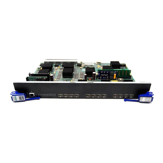
Figure 1-2 7G4270-12, 7G4202-30, and 7H4203-72 DFE Modules À Á Â Ã Ä Å 1 RESET switch 2 RJ45 COM (Console Port) 3 CPU LED 4 MGMT LED 5 7G4270-12 - GROUP STATUS LEDs 7G4202-30/7H4203-72 GROUP SELECT switch À Á... -
Page 30: Connectivity
Network Expansion Module Option The 7H4382-49 and 7H4383-49 option slots provide access to an installed network expansion module (NEM). Refer to the Enterasys Networks web site for a current listing of the available NEMs. Specific installation instructions are shipped with each NEM. -
Page 31: Management
Switch Configuration Using CLI Commands The CLI commands enable you to perform more complete switch configuration management tasks. For CLI command set information and how to configure the module, refer to the Enterasys Matrix DFE-Platinum Series Configuration Guide. Appendix A. The 7G4270-12 ®... -
Page 32: Secure Networks Policy Support
Classification Rules determine how specific traffic flows (identified by Layer 2, Layer 3, and Layer 4 information in the data packet) are treated by each Switch or Router. In general, Classification Rules are applied to the networking infrastructure at the network edge/ingress point. -
Page 33: Network Requirements
Failure to do so will produce poor network performance. Note: The Enterasys Matrix DFE-Platinum Series Configuration Guide and the Cabling Guide referred to in the following sections can be found on the Enterasys Networks World Wide Web site: Refer to “Related Documents”... -
Page 34: Module Placement In A Matrix E7 Chassis
Aggregation. The default values will result in the maximum number of aggregations possible. If the switch is placed in a configuration with its peers not running the protocol, no aggregations will be formed and the DFE modules will function normally (that is, Spanning Tree will block redundant paths). -
Page 35: 100Base-Tx Network
100BASE-TX NETWORK The fixed front panel ports of the 7H4382-49, 7H4383-49, and 7H4203-72 provide a connection that supports Category 5 UTP cabling. The device at the other end of the twisted pair segment must meet IEEE 802.3-2002 100BASE-TX Fast Ethernet network requirements for the devices to operate at 100 Mbps. - Page 36 1000BASE-T Network Network Requirements...
-
Page 37: Important Notice
Electrical Hazard: Only qualified personnel should perform installation procedures. Riesgo Electrico: Solamente personal calificado debe realizar procedimientos de instalacion. Elektrischer Gefahrenhinweis: Installationen sollten nur durch ausgebildetes und qualifiziertes Personal vorgenommen werden. Read the Release Notes shipped with the DFE module to check for any exceptions to the supported features and operation documented in this guide. -
Page 38: Unpacking The Dfe Module
Note: Install any optional equipment before proceeding to of the rules to install different series modules in a Matrix E7 chassis. Refer to your release notes or the Enterasys Networks web site for the latest available network expansion modules (NEMs). -
Page 39: Installing An Optional Mini-Gbic
INSTALLING AN OPTIONAL MINI-GBIC This section describes how to install a Mini-GBIC in an optional NEM or in any of the 7G4270-12 front panel ports (1-12). Warning: Fiber-optic Mini-GBICs use Class 1 lasers. Do not use optical instruments to view the laser output. The use of optical instruments to view laser output increases eye hazard. -
Page 40: Mini-Gbic With Mt-Rj Connector
Installing an Optional Mini-GBIC 2. Remove the Mini-GBIC from the packaging. 3. If there is a protective dust cover (see 5 in not remove it at this time. Installation To install a Mini-GBIC with an MT-RJ connection, refer to Figure 3-2, or for an RJ45 connection, refer to 1. -
Page 41: Mini-Gbic With Lc Connector
Figure 3-2 Mini-GBIC with LC Connector 1 Mini-GBIC (MGBIC-LC01 or MGBIC-LC09) 2 Mini-GBIC top side 3 7-Pin edge connector (insertion side) Figure 3-3 Mini-GBIC with RJ45 Connector Ä 1 Mini-GBIC (MGBIC-02) 2 Mini-GBIC, top side 3 7-Pin edge connector (insertion side) Installing an Optional Mini-GBIC 4 Port slot 5 Mini-GBIC... -
Page 42: Removing The Mini-Gbic
Installing an Optional Mini-GBIC Removing the Mini-GBIC Caution: Do NOT remove a Mini-GBIC from a slot without releasing the locking tab located under the front bottom end of the Mini-GBIC The Mini-GBIC and its host device are sensitive to static discharges. Use an antistatic wrist strap and observe all static precautions during this procedure. -
Page 43: Backplane Connections And Installation Rules
The 7H4382-49 has a connection to both FTM1 and FTM2 backplanes, which enables the 7H4382-49 to switch frames between the two backplanes and all modules in the 6C107 chassis. However, the older first (6x1xx), second (6x2xx), and third (6x3xx) generation modules are still managed using their own Local Management and are not subject to management by the DFE module management entity. -
Page 44: Module Placement And Rules
Backplane Connections and Installation Rules 3.4.2 Module Placement and Rules Depending on the modules being installed in the Matrix E7 chassis and to help ensure proper operation, consider the following examples and rules for module placement in the chassis. Figure 3-4 shows five examples of chassis module placement. - Page 45 Example 3 (Figure 3-4, C) Shows chassis slots 1 through 5 populated with first and second generation modules (6x1xx and 6x2xx). If a 6x1xx or 6x2xx series module is installed in slot 6 or 7, it will operate in standalone mode (no backplane connectivity).
- Page 46 Backplane Connections and Installation Rules Example 5 (Figure 3-4, E) Shows chassis slots 1 and 5 populated with 6x1xx, 6x2xx modules, respectively; slots 2 through 4 with DFE modules, but not a bridging module (such as the 7H4382-25, 7H4382-49, 7H4383-49, or 7H4385-49);...
-
Page 47: Installing Module Into Matrix E7 Or N7 Chassis
Observe all precautions to prevent damage from Electrostatic Discharge (ESD). 5. Examine the module for damage. If any damage exists, DO NOT install the module. Immediately contact Enterasys Networks. Refer to Installing Module into Matrix E7 or N7 Chassis Section 3.4... - Page 48 Installing Module into Matrix E7 or N7 Chassis Installation To install the module, refer to Caution: To prevent damaging the backplane connectors in the following step, take care that the module slides in straight and properly engages the backplane connectors. Ensure that the top lever lines up with the desired slot number located on the front panel of the chassis.
-
Page 49: Installing Module Into Matrix E7 Or Matrix N7 Chassis (E7 Shown)
Figure 3-5 Installing Module into Matrix E7 or Matrix N7 Chassis (E7 shown) Card guides Slot number 6 (Left-most slot is 1) Module card Metal back panel Installing Module into Matrix E7 or N7 Chassis Æ Á Ã Â À Upper/lower locking tabs (in proper open position) Upper/lower locking tab (in closed position) Backplane connectors... -
Page 50: Installing Module Into Matrix N3, N1, Or N5 Chassis
Installing Module into Matrix N3, N1, or N5 Chassis INSTALLING MODULE INTO MATRIX N3, N1, OR N5 CHASSIS Caution: Failure to observe static safety precautions could cause damage to the module. Follow static safety handling rules and wear the antistatic wrist strap. Do not cut the non-conductive bag to remove the module. -
Page 51: Installing Module Into Matrix N1, N3, Or N5 Chassis (Matrix N3 Shown)
Figure 3-6 Installing Module into Matrix N1, N3, or N5 Chassis (Matrix N3 shown) Æ Ä Card guides Slot 1 (Top slot is slot 3.) Module card Metal back panel Installing Module into Matrix N3, N1, or N5 Chassis à À... -
Page 52: Connecting To The Network
Link Aggregation to operate properly. Before connecting the cables, refer to the Enterasys Matrix DFE-Platinum Series Configuration Guide for the configuration information. For details on how to obtain manuals, refer to the About This Guide 3.7.1... -
Page 53: Connecting A Twisted Pair Segment To The 7H4382-49
Figure 3-7 Connecting a Twisted Pair Segment to the 7H4382-49 1 RJ45 connector 3. Verify that a link exists by checking that the port RX (Receive) LED is ON (flashing amber, blinking green, or solid green). If the RX LED is OFF and the TX (Transmit) LED is not blinking amber, perform the following steps until it is on: a. -
Page 54: Crossover 4-Wire Cable Rj45 Pinouts, Connections Between Hub Devices
Connecting to the Network d. Verify that the RJ45 connectors on the twisted pair segment have the proper pinouts and check the cable for continuity. Typically, a crossover cable is used between hub devices. A straight-through cable is used to connect between switches or hub devices and an end user (computer). -
Page 55: Eight-Wire Crossover Cable Rj45 Pinouts, Connections Between Hub Devices
Figure 3-10 Eight-Wire Crossover Cable RJ45 Pinouts, Connections Between Hub Devices 1 RJ45 device port 2 Other device port Figure 3-11 Eight-Wire Straight-Through Cable RJ45 Pinouts, Connections Between Switches and End User Devices 1 RJ45 device port 2 Other device port À... -
Page 56: Connecting Utp Cables To The 7H4383-49 Or 7H4203-72
Ensure that the twisted pair connection meets the dB loss and cable specifications outlined in the Cabling Guide. Refer to on obtaining this document. If a link is not established, contact Enterasys Networks. Refer to details. 4. Repeat steps 1 through 3 above, until all connections have been made. -
Page 57: Connecting A Twisted Pair Segment Using Rj21 Straight Connector
RJ21 port connector 3. To install an RJ21 right-angle connector, refer to a. If using an optional RJ21 angle adapter available from Enterasys Networks, insert the angle adapter into the RJ21 port connector. b. Tighten the two screws to secure the RJ21 angle adapter to the RJ21 port connector. -
Page 58: Connection Using Optional Rj21 Angle Adapter
Connecting to the Network Figure 3-13 Connection Using Optional RJ21 Angle Adapter Ä À Ã RJ21 angle adapter RJ21 port connector Retaining screws 3-22 Installation Á Â Â Ä RJ21 right-angled connector Retaining clips... -
Page 59: Example Of Cable Placement When Using Optional Rj21 Angle Adapters
Figure 3-14 Example of Cable Placement When Using Optional RJ21 Angle Adapters 4. Verify that a link exists by checking that the port RX (Receive) LED is ON (flashing amber, blinking green, or solid green). If the RX LED is OFF and the TX (Transmit) LED is not blinking amber, perform the following steps until it is on: a. -
Page 60: Connecting Fiber-Optic Cables To Mini-Gbics
Check that the twisted pair connection meets the specifications in the Cabling Guide. If a link is not established, contact Enterasys Networks. Refer to details. 5. Repeat all the steps above until all RJ21 connections are made. - Page 61 Caution: Do not touch the ends of the fiber-optic strands, and do not let the ends come in contact with dust, dirt, or other contaminants. Contamination of cable ends causes problems in data transmissions. If the ends of the fiber-optic strands become contaminated, use a canned duster to blow the surfaces clean.
-
Page 62: Cable Connection To Mt-Rj Fiber-Optic Connectors
Connecting to the Network Figure 3-15 Cable Connection to MT-RJ Fiber-Optic Connectors 1 Installed Mini-GBIC MT-RJ connecto 2 MT-RJ cable connector 3 Release tab 3-26 Installation à À Á À  4 Receive LED (RX) 5 Transmit LED (TX) Ä... -
Page 63: Cable Connection To Lc Fiber-Optic Connectors
Figure 3-16 Cable Connection to LC Fiber-Optic Connectors 1 Installed Mini-GBIC LC connector 2 LC cable connector 3 Release tab 3. Verify that a link exists by checking that the port RX LED is on (flashing amber, blinking green, or solid green). If the RX LED is off, perform the following steps until it is on: Ã... -
Page 64: Connecting To Com Port For Local Management
This section describes how to install a UTP cable with RJ45 connectors and optional adapters to connect a PC, a VT series terminal, or a modem to an Enterasys Networks module to access Local Management. This section also provides the pinout assignments of the adapters. -
Page 65: Connecting To An Ibm Pc Or Compatible Device
Enterasys Networks module COM port 1. Connect the RJ45 connector at one end of the cable the Enterasys Networks module. (The COM port is also known as a Console port.) 2. Plug the RJ45 connector at the other end of the cable ➂... -
Page 66: Connecting To A Vt Series Terminal
2 RJ45-to-DB9 PC adapter 3.8.3 Connecting to a VT Series Terminal To connect a VT Series terminal to an Enterasys Networks DFE module COM port use a UTP cable with RJ45 connectors and an optional RJ45-to-DB25 female adapter, and proceed as follows: 1. -
Page 67: Connecting To A Modem
3.8.4 Connecting to a Modem To connect a modem to an Enterasys Networks DFE module COM port cable with RJ45 connectors and an optional RJ45-to-DB25 male adapter, and proceed as follows: 1. Connect the RJ45 connector at one end of the cable to the COM port of the module. -
Page 68: Connecting To A Modem
Bits Parity Stop Bit 6. When these parameters are set, the Local Management password screen will display. Refer to the Enterasys Matrix DFE-Platinum Series Configuration Guide for further information. Figure 3-19 Connecting to a Modem 1 UTP cable with RJ45 connectors... -
Page 69: Adapter Wiring And Signal Assignments
3.8.5 Adapter Wiring and Signal Assignments COM Port Adapter Wiring and Signal Diagram RJ45 Conductor Blue Green Orange Yellow VT Series Port Adapter Wiring and Signal Diagram RJ45 Conductor Blue Yellow Green Orange Connecting to COM Port for Local Management Signal Receive (RX) Transmit (TX) -
Page 70: Completing The Installation
In a new system of DFE modules, one of the installed DFE modules will become the management module on chassis power up, and all DFE modules will automatically be set to the factory default values. A complete list of the factory default values are provided in Chapter 3 of the Enterasys Matrix DFE-Platinum Series Configuration Guide. -
Page 71: First-Time Log-In Using A Console Port Connection
The Enterasys Matrix DFE-Platinum Series Configuration Guide is available online at: http://www.enterasys.com/support/manuals If you require assistance, contact Enterasys Networks using one of the methods described in “Getting Help” on page xxii. -
Page 72: Completing The Installation Of A Dfe Module In An Existing System
If you need to change any settings, you can connect a terminal to the local console port as described in Section 3.8 to access system management, or use a Telnet connection to access the DFE module system management as described in Chapter 3 of the Enterasys Matrix DFE-Platinum Series Configuration Guide. 3-36 Installation... -
Page 73: Logging In With An Administratively-Configured User Account
For information on the set password and set system login commands, refer to Chapter 3 in the Enterasys Matrix DFE-Platinum Series Configuration Guide The DFE module is now ready to be configured. - Page 74 Completing the Installation 3-38 Installation...
-
Page 75: Troubleshooting
This chapter provides information concerning the following: • Using LANVIEW (Section • Troubleshooting Checklist • DFE Module Shutdown Procedures (Special Instructions) • Recommended Shutdown Procedure Using RESET Button • Last Resort Shutdown Procedure Using RESET Button Unless otherwise noted, the following information applies to all DFE modules. USING LANVIEW The modules use a built-in visual diagnostic and status monitoring system called LANVIEW. -
Page 76: Lanview Leds
Using LANVIEW (Groups 1 through 4). Each time the GROUP SELECT button is pressed, the GROUP LED lights up in sequence, indicating which group is selected. The receive and transmit activity for that group of segments is then indicated by the RX and TX LEDs for each port. Figure 4-1 LANVIEW LEDs 1 MGMT LED Table 4-1... - Page 77 None. None. None. Ensure chassis has adequate power. None. If the LED remains amber for several minutes, contact Enterasys Networks for technical support. None. None. None. None. This state is activated when the RESET button is pressed for less than 1 second to a start the process of an orderly shutdown.
- Page 78 None. Contact Enterasys Networks for technical support. If it is known that the port should be active and is not, contact Enterasys Networks for technical support. None. None, unless there is a high rate of activity. In this case, check for network configuration problems or a defective device.
-
Page 79: Troubleshooting Checklist
Recommended Action Ensure that the module was installed properly according to the installation instructions in Chapter chassis is providing power. Refer to the Enterasys Matrix DFE-Platinum Series Configuration Guide for proper setup procedures. Refer to Appendix A for proper COM port pinouts. - Page 80 Recommended Action Refer to the Enterasys Matrix DFE-Platinum Series Configuration Guide for the IP address assignment procedure. Enable port. Refer to the Enterasys Matrix DFE-Platinum Series Configuration Guide for instructions to enable/disable ports. Verify that a management VLAN exists and that it is associated with the Host Port.
- Page 81 Troubleshooting Checklist Recommended Action Reenter the lost parameters as necessary. Refer to the Enterasys Matrix DFE-Platinum Series Configuration Guide for the instructions to configure the device. If the problem continues, contact Enterasys Networks for technical support.
-
Page 82: Overview Of Dfe Module Shutdown Procedure
The DFE modules installed in a Matrix E7, Matrix N3, or Matrix N7 chassis are interdependent and operate under a single IP address as a single, distributed switch system (hardware, databases, and persistent storage). In this operating environment, the DFE module must shut down in an orderly fashion to ensure that the other modules in the system and other devices on the network are notified of the impending change. -
Page 83: Recommended Shutdown Procedure Using Reset Button
4.3.1 Recommended Shutdown Procedure Using RESET Button Caution: Do not pull any DFE module out of an operating chassis before it has completed its shutdown routine. Precaución: No retire los módulos DFE del chasis en funcionamiento hasta que no se haya terminado con la rutina de apagado. - Page 84 Overview of DFE Module Shutdown Procedure 4-10 Troubleshooting...
-
Page 85: A.1 Dfe Module Specifications
• COM port pinout assignment • Regulatory compliance Enterasys Networks reserves the right to change the specifications at any time without notice. DFE MODULE SPECIFICATIONS Table A-1 provides the I/O ports, processors and memory, physical, and environmental module specifications for the 7H4382-49, 7H4383-49, 7G4270-12, 7G4202-30, and 7H4203-72 DFE modules. - Page 86 Gross: 5.54 kg (12.0 lb) (shipping carton containing one module) Net: 4.10 kg (9.0 lb) (one module without packaging) For the MTBF hours for these products, refer to the MTBF web site at URL http://www.enterasys.com/support/mtbf/ for a list of the...
-
Page 87: Mini-Gbic Input/Output Specifications
Table A-1 Specifications (Continued) Item Environmental Operating Temperature Storage Temperature Operating Relative Humidity MINI-GBIC INPUT/OUTPUT SPECIFICATIONS The Mini-Gigabit Ethernet Card (Mini-GBIC) port interface slots can accept 1000BASE-SX short wavelength or 1000BASE-LX long wavelength fiber-optic Mini-GBICs (see optional Mini-GBICs are hot swappable. Table A-2 Mini-GBIC Input/Output Port Specifications Item MGBIC-LC01... -
Page 88: Gigabit Ethernet Specifications
Gigabit Ethernet Specifications GIGABIT ETHERNET SPECIFICATIONS The following specifications for the Mini-GBICs (shown in exceed the IEEE 802.3z-1998 standard. A.3.1 MGBIC-LC01/MGBIC-MT01 Specifications (1000BASE-SX) Table A-3 MGBIC-LC01 / MGBIC-MT01 Optical Specifications Item Transmit Power (minimum) Receive Sensitivity Link Power Budget Table A-4 MGBIC-LC01 / MGBIC-MT01 Operating Range Item 62.5 µm MMF 62.5 µm MMF... -
Page 89: Mgbic-Lc03 Specifications (1000Base-Sx
A.3.2 MGBIC-LC03 Specifications (1000BASE-SX) Table A-5 MGBIC-LC03 Optical Specifications Item Transmit Power (minimum) Transmit Power (maximum) Receive Sensitivity Link Power Budget (Multimode Only) 1. The maximum drive distance (up to 2 km) depends on the quality of the installed multimode fiber-optic cable segment. -
Page 90: Mgbic-08 Specifications (1000Base-Elx
Gigabit Ethernet Specifications Table A-8 MGBIC-LC09 Operating Range Item 62.5 µm MMF 50 µm MMF 50 µm MMF 10 µm SMF A.3.4 MGBIC-08 Specifications (1000BASE-ELX) Table A-9 MGBIC-08 Optical Specifications Item Transmit Power (minimum) Receive Sensitivity Maximum Input Power Link Power Budget (Full Duplex Only) 1. -
Page 91: Mgbic-02 Specifications (1000Base-T
A.3.5 MGBIC-02 Specifications (1000BASE-T) Table A-11 MGBIC-02 / Specifications Item Supported Cable Type: Maximum Length Connector Data Rate TX Output impedance RX Input impedance Specification Copper, Category 5 UTP Up to 100 meters RJ45 1 Gbps, IEEE 802.3:2000 compatible 1000BASE-T operation only Automatic crossover detection 100 ohms, typical at all frequencies between 1 MHz and 125 MHz... -
Page 92: A.5 Regulatory Compliance
COM Port Pinout Assignments COM PORT PINOUT ASSIGNMENTS The COM port is a serial communications port for local access to Local Management. Refer to Table A-12 for the COM port pin assignments. Table A-12 COM Port Pin Assignments Signal Name Transmit Data (XMT) Data Carrier Detect (DCD) Data Set Ready (DSR) -
Page 93: B.1 Required Tools
Precaución: Para llevar a cabo los procedimientos especificados en el apéndice deberá utilizar una pulsera antiestática. Esta pulsera sirve para minimizar los efectos de las descargas de electricidad estática. Mode Switch Bank Settings and Optional Installations B.1) Mode Switch Bank Settings and Optional Installations (Section B.2) (Section B.3) -
Page 94: Setting The Mode Switches
Once the module resets, you can either use the factory default settings or reenter your own password. Note: Do not change the position of Switch 8 unless it is necessary to reset the admin password to its factory default setting. -
Page 95: Mode Switch Location On 7H4382-49 And 7H4383-49
Figure B-1 Mode Switch Location on 7H4382-49 and 7H4383-49 1 Mode switch bank (located in same location on both the 7H4382-49 and 7H4383-49) Figure B-2 Mode Switch Location on 7G4270-12 1 Mode switch bank Mode Switch Bank Settings and Optional Installations Setting the Mode Switches ➀... -
Page 96: Mode Switch Location On 7G4202-30
1 Mode switch bank • Switch 7 – Clear Persistent Data. Changing the position of this switch clears Persistent Data on the next power-up of the module. All user-entered parameters, such as the IP address, module names, etc., are reset to the factory default settings. Once the module resets, you can either use the factory default settings or reenter your own parameters. -
Page 97: Memory Locations And Replacement Procedures
Once the module resets, you can either use the factory default settings or reenter your own password. Note: Do not change the position of Switch 8 unless it is necessary to reset the admin password to its factory default setting. -
Page 98: Dram Simm Replacement Procedure (For 7H4382-49 And 7H4383-49
In the event that the DRAM Single In-line Memory Module (SIMM) needs to be replaced, the following sections explain how to remove and install the SIMM. If you have questions concerning the replacement of the SIMM, refer to Enterasys Networks. Caution: Observe all antistatic precautions when handling sensitive electronic equipment. -
Page 99: Nem Removal And Dram Simm Connector Location 7H4382-49 Or 7H4383-49
3. Remove the module from the connector. Memory Locations and Replacement Procedures ➃ ➂ 4 DFE module front panel 5 Module connectors on main board 6 DRAM SIMM memory module Mode Switch Bank Settings and Optional Installations ➄ ➁ ➅ ➀... -
Page 100: Removing The Existing Dram Simm From 7H4382-49 Or 7H4383-49
DRAM SIMM alignment notches. 2. Push the DRAM SIMM further into the connector until the two DRAM SIMM alignment notches and the tabs on the two connector arms lock the DRAM SIMM into place. Mode Switch Bank Settings and Optional Installations À Â... - Page 101 DRAM SIMM from the connector contacts. Memory Locations and Replacement Procedures à Á À  3 Connector fingers 4 DRAM SIMM alignment notches (2) Mode Switch Bank Settings and Optional Installations 7H4383-49 à À Figure B-6. Figure B-10, enough to...
- Page 102 DRAM SIMM alignment notches. 3. Push the DRAM SIMM down into the connector contacts. Then rotate the two connector arms toward the DRAM SIMM to lock it into place. B-10 Mode Switch Bank Settings and Optional Installations Á Â DRAM SIMM...
- Page 103 Figure B-11 Installing the DRAM SIMM À DRAM SIMM Connector arms DRAM SIMM Memory Locations and Replacement Procedures à Á  Connector contacts DRAM SIMM alignment notches (2) Mode Switch Bank Settings and Optional Installations à À B-11...
-
Page 104: Dimm Replacement Procedure (All Dfe Modules
In the event that the Dual In-line Memory Module (DIMM) needs to be replaced, the following sections explain how to remove and install the DIMM. If you have questions concerning the replacement of the DIMM, refer to Enterasys Networks. Removing the DIMM Caution: Observe all Electrostatic Discharge (ESD) precautions when handling sensitive electronic equipment. -
Page 105: Installing The Dimm
Then release the two connector arms to lock the DIMM into place. Memory Locations and Replacement Procedures À  2 DIMM Figure B-13 and proceed as follows: Mode Switch Bank Settings and Optional Installations Á À Connector fingers B-13... - Page 106 Memory Locations and Replacement Procedures Figure B-13 Installing the DIMM 1 DIMM 2 Connector fingers B-14 Mode Switch Bank Settings and Optional Installations à  Á 3 Connector arms 4 DIMM alignment notches (2) À à Â...
- Page 107 Numerics 1000BASE-SX/LX network connections requirements for 100BASE-TX requirements 10BASE-T connection 3-16, 3-20 requirements 7G4202-30 introduction to 7G4270-12 introduction to 7H4203-72 introduction to 7H4382-49 introduction to 7H4383-49 introduction to Cable Fiber budget Cable connections 7H4382-49 and 7G4202-30 7H4383-49 or 7H4203-72 3-20 Cable specifications 1000BASE-SX/LX network 100BASE-TX network...
- Page 108 MGBIC-LC03 specifications for MGBIC-LC09 specifications for Mini-GBIC installation of 3-16 removal of specifications for Mode Switch 3-14 setting of Module features Network connecting to Network expansion module option introduction to Network Requirements list of Optional network expansion module...
- Page 109 Specifications, MGBIC-LC09 operating range optical Specifications, MGBIC-MT01 operating range optical Standards compatibility Technical support contatacting Enterasys for xxii Transmit LEDs viewing of Troubleshooting checklist for Unpacking the module User Personalized Networks (UPN) See Secure Networks Policy Support. UTP cable connections...
- Page 110 Index-4...
Need help?
Do you have a question about the Matrix 7G4270-12 and is the answer not in the manual?
Questions and answers