
Related Manuals for Enterasys WS-AP36OUTNAM


Summary of Contents for Enterasys WS-AP36OUTNAM
- Page 1 Enterasys Wireless ® Outdoor AP3620 NEMA Solution Installation Guide WS-AP36OUTNAM P/N 9034551-03...
- Page 3 Notice Enterasys Networks reserves the right to make changes in specifications and other information contained in this document and its web site without prior notice. The reader should in all cases consult Enterasys Networks to determine whether any such changes have been made. The hardware, firmware, or software described in this document is subject to change without notice. IN NO EVENT SHALL ENTERASYS NETWORKS BE LIABLE FOR ANY INCIDENTAL, INDIRECT, SPECIAL, OR CONSEQUENTIAL DAMAGES WHATSOEVER (INCLUDING BUT NOT LIMITED TO LOST PROFITS) ARISING OUT OF OR RELATED TO THIS DOCUMENT, WEB SITE, OR THE INFORMATION CONTAINED IN THEM, EVEN IF ENTERASYS NETWORKS HAS BEEN ADVISED OF, KNEW OF, OR SHOULD HAVE KNOWN OF, THE POSSIBILITY OF SUCH DAMAGES. Enterasys Networks, Inc. 50 Minuteman Road Andover, MA 01810 © 2011 Enterasys Networks, Inc. All rights reserved. Part Number: 9034551‐03 February 2011 ENTERASYS, ENTERASYS NETWORKS, ENTERASYS SECURE NETWORKS, and any logos associated therewith, are trademarks or registered trademarks of Enterasys Networks, Inc., in the United States and/or other countries. For a complete list of Enterasys trademarks, see http://www.enterasys.com/company/trademarks.aspx. All other product names mentioned in this manual may be trademarks or registered trademarks of their respective companies. Documentation URL: https://extranet.enterasys.com/downloads...
-
Page 5: Table Of Contents
Preparing the Enclosure and AP3620 ...................... 2-2 Installing the Prepared Enclosure ......................2-5 Appendix A: Specifications Figures Open WS-AP36OUTNAM Enclosure without AP3620 Installed ............2-3 Location of Antenna Connectors on AP3620 ..................2-4 Location of Ports on AP3620......................2-4 Attaching Pole Mount Brackets ......................2-5 Attaching Enclosure to Pole ....................... -
Page 7: About This Guide
About This Guide This guide provides an overview and installation instructions for the Enterasys Outdoor AP3620 NEMA solution, model WS‐AP36OUTNAM. Who Should Use This Guide Electrical Hazard: Only qualified personnel should install or service this unit. Riesgo Electrico: Nada mas personal capacitado debe de instalar o darle servicio a esta unida. Elektrischer Gefahrenhinweis: Installationen oder Servicearbeiten sollten nur durch ausgebildetes und qualifiziertes Personal vorgenommen werden. -
Page 8: Typographical Conventions
World Wide Web www.enterasys.com/support/ Phone 1-800-872-8440 (toll-free in U.S. and Canada) or 1-978-684-1000 For the Enterasys Networks Support toll-free number in your country: www.enterasys.com/support/ Internet mail support@enterasys.com To expedite your message, please type [wireless] in the subject line. To send comments or suggestions concerning this document to the Technical Publications Department: techpubs@enterasys.com... - Page 9 Getting Help • A description of your network environment (such as layout, cable type, other relevant environmental information) • Network load and frame size at the time of trouble (if known) • The device history (for example, if you have returned the device before, or if this is a recurring problem) • Any previous Return Material Authorization (RMA) numbers Outdoor AP3620 NEMA Solution Installation Guide vii...
- Page 10 Getting Help viii About This Guide...
-
Page 11: Chapter 1: Safety Warnings
Safety Warnings Carefully observe these instructions and any special instructions that are included with the equipment you are installing. Injury, electrical shock, or death may occur if these precautions are not followed. This product should be installed and serviced by a qualified licensed technician, electrician, or electrical maintenance person familiar with its operation and the hazards involved. Proper installation, which includes wiring, mounting, fusing or other over current protection and grounding, can reduce the chance of electric shocks, fires, or explosion in this product or products used within this product. Electrical Hazard: To avoid electric shock, grounding must be installed by the customer as part of the installation. The unit must be grounded and installed in accordance with National Electrical Codes (NEC) and any local codes. -
Page 12: To Avoid Falling, Use Safe Procedures When Working At Heights Above Ground
Important Notices To Avoid Falling, Use Safe Procedures When Working At Heights Above Ground • Select equipment locations that will allow safe, simple equipment installation. • Don’t work alone. A friend or co‐worker can save your life if an accident happens. • Use approved non‐conducting ladders and other safety equipment. Make sure all equipment is in good repair. • If an enclosure of mast begins falling, don’t attempt to catch it. Stand back and let it fall. • If anything such as an enclosure or mast does come in contact with a power line, DON’T TOUCH IT OR ATTEMPT TO MOVE IT. Instead, save your life by calling the power company. • Don’t attempt to install an enclosure on windy days. If a Person Comes In Contact With Electrical Power and Cannot Move Don’t touch that person, or you may be electrocuted. -
Page 13: Chapter 2: Outdoor Ap3620 Nema Solution Description And Installation
C). Surge protection is provided on the internal AC outlets, and 3 bulkhead‐mount Reverse Polarity Type‐N Jack form factor lightning protectors are installed for connections to the external antennas. In addition to the AP3620, the solution also includes a PoE power injector, all necessary cables to complete the installation of the AP in the enclosure, and a pole mount kit. Solution Contents The outdoor solution includes the following components: • One Enterasys Wireless 802.11n AP3620 (WS‐AP3620), with wall mounting bracket. One plastic rivet (to secure the AP to the bracket) and other screws are packaged with the wall mounting bracket in a small plastic bag. • One fiberglass enclosure, with PoE adapter, lightning protectors, and cables installed. • One pole mount kit (accommodates poles from 2 to 4 inches in diameter). Note: The kit contains U bolts suitable for 2 to 4 inch diameter poles, but the brackets in the kit have holes that can accommodate smaller U bolts for 1.25 to 2 inch diameter poles. You can supply your own smaller U bolts and attach the enclosure to a smaller diameter pole. -
Page 14: Installation Procedures
Installation Procedures • Antennas: – WS‐AO‐DS05360 — Outdoor, 2.4‐2.5/5.15‐5.875 GHz, 5 dBi, Omni, Baton, 1 x Reverse Polariazed Type‐N connector. – WS‐AO‐5D16060 — Outdoor, 5.15‐5.875 GHz, Dual‐polarization 16 dBi, 60 deg, Sector, 2 x Reverse Polarized Type‐N connectors. – WS‐AO‐5D23009 — Outdoor, 5.15‐5.875 GHz, Dual‐polarization, 23 dBi, 9 deg, Panel, 2 x Reverse Polarized Type‐N connectors. Refer to the Enterasys Wireless AP External Antenna Site Preparation and Installation Guide for more information about these antennas. This document is available on the Enterasys Networks downloads web site. • Terminator cap. If you are not attaching three antennas to the AP3620, you must use a terminator cap on the antenna connector not being used. – WS‐CAB‐RPSMATERM — Terminator, Reverse Polarity SMA PLUG 50 OHM 1W • Cables to connect the lightning protectors on the enclosure to the antennas. All cables listed below have Reverse Polarity Type‐N female connectors at both ends. – RBTES‐L200‐C20F — 20 foot LMR200 cable – RBTES‐L400‐C06F — 6 foot LMR400 cable – RBTES‐L400‐C50F — 50 foot LMR400 cable – RBTES‐L400‐C75F — 75 foot LMR400 cable – RBTES‐L600‐C25F — 25 foot LMR600 cable – RBTES‐L600‐C50F — 50 foot LMR600 cable Installation Procedures Electrical Hazard: This product should be installed and serviced by a qualified licensed technician, electrician, or electrical maintenance person familiar with its operation and the hazards involved. -
Page 15: Open Ws-Ap36Outnam Enclosure Without Ap3620 Installed
When you open the AP3620 box, be sure to set aside the cardboard sleeve containing the AP’s mounting bracket, various screws, and plastic rivet for use later in Step 4 and Step 9. Place the enclosure back down on a flat surface and open the enclosure door. The contents of the enclosure are illustrated in Figure 2‐1 below. Figure 2-1 Open WS-AP36OUTNAM Enclosure without AP3620 Installed Removable filter Cable to connect PoE injector to AP Cooling fan Cables to connect lightning protectors to AP PoE injector antenna connectors Mounting plate PoE injector power cord Remove the AP’s wall mount bracket from the cardboard sleeve. Then, using the three ... -
Page 16: Location Of Antenna Connectors On Ap3620
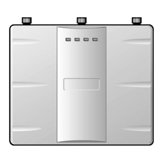
Installation Procedures Figure 2-2 Location of Antenna Connectors on AP3620 3 antenna connectors (Reverse Polarity SMA plugs) Connect the cables attached to the lightning protectors to the antenna connectors (Reverse Polarity SMA plugs) at the top of the AP3620 using the right‐angle SMA connectors on the loose cable ends. Maintain the same right‐to‐left correspondence of the AP’s connectors with the lightning protectors. Caution: If you are not using three external antennas, do not connect the cable attached to an unused lightning protector to any of the antenna connectors on the AP3620. You must attach a terminator cap to any unused connectors on the top of the AP. -
Page 17: Installing The Prepared Enclosure
Installation Procedures The following procedure describes the steps to install the prepared enclosure outside. Installing the Prepared Enclosure The following procedure assumes that you are installing the enclosure on a pole. If you are installing the enclosure on a wall, use the holes on the top and bottom extensions of the enclosure to bolt the enclosure to the wall and proceed with Step 3 below. To install the prepared enclosure: If you will install the enclosure on a pole, open the pole mount kit box. Attach the pole mount brackets to the top and bottom of the enclosure using the four bolts, nuts, and washers included with the pole mount kit, as shown in Figure 2‐4 below. Set aside the two U bolts and remaining washers and nuts for use in the next step. Figure 2-4 Attaching Pole Mount Brackets Bolts (4) Bracket (2) Washers (8) Nuts (4) Enclosure hole for bracket attachment (4) Place the enclosure on the pole in the desired location and orientation, then slip the two U bolts around the pole and into the holes on the top and bottom brackets. Use the remaining four washers and nuts to tighten the U bolts to hold the enclosure securely on the pole, as shown in Figure 2‐5 on page 2‐6. -
Page 18: Attaching Enclosure To Pole
Installation Procedures Note: Figure 2-5 also shows the location of the holes that can be used with smaller, customer-supplied U bolts to attach the enclosure to a 1.25 to 2 inch diameter pole. Figure 2-5 Attaching Enclosure to Pole Nuts (4) Pole Washers (4) U bolts (2) -
Page 19: Bottom Of Enclosure
Installation Procedures Figure 2-6 Bottom of Enclosure External grounding lug Network cable connector Cable conduit connector Lightning protectors (3) Optionally, if the AP being installed will be connected to the wired network, thread the network cable (with RJ45 connector attached) through the network cable connector on the bottom of the enclosure and attach the cable to the IN port on the top of the PoE injector. Caution: Do not run the network cable through the cable conduit connector used for connecting the power cables. You must connect the network cable and power cables through separate connectors. Attach a ground to earth cable to the grounding lug on the bottom outside of the enclosure, ... -
Page 20: Connecting Power Wires
Installation Procedures Figure 2-7 Connecting Power Wires Neutral terminal Ground terminal Line terminal Close the enclosure and optionally lock it. Attach the separately ordered antenna cables to the lightning protector connectors on the outside bottom of the enclosure (shown in Figure 2‐6 on page 2‐7). This completes the installation of the WS‐AP36OUTNAM solution. For information about installing the antennas, refer to the Enterasys Wireless AP External Antenna Site Preparation and Installation Guide available on the Enterasys Networks web site at this URL: https://extranet.enterasys.com/downloads 2-8 Outdoor AP3620 NEMA Solution Description and Installation... - Page 21 Specifications This appendix lists the specifications for the NEMA‐rated enclosure. Table A-1 Specifications for the WS-AP36OUTNAM Enclosure Item Specification Enclosure material Fiberglass reinforced polyester Voltage 120 VAC Heater power 200 Watts Fan power 22 Watts Weight 18.1 lbs (8.21 kg) Mounting plate material .10” (2.5mm) thick anodized aluminum Outside dimensions (max) 15.5 x 13.5 x 8.7 inches...
- Page 22 A-2 Specifications...
Need help?
Do you have a question about the WS-AP36OUTNAM and is the answer not in the manual?
Questions and answers