
Related Manuals for Ko Propo EX-NEXT


Summary of Contents for Ko Propo EX-NEXT
- Page 1 EX-NEXT INSTRUCTION MANUAL *Please refer barcode label for content. *Please refer included manual for LDT grip unit. KONDO KAGAKU Co., Ltd. 2021 Ver.1.00...
-
Page 2: Table Of Contents
■ Table of Contents ■ Table of Contents *Click the page number to jump to that page. Title Title Page Page ■ Table of Contents READ ID ■ For safe operation MODEL(Servo model) ■ Getting Started BT F/S (Battery Fail-safe) ●Transmitter Assembly ●SYSTEM ●Transmitter Dismantling... -
Page 3: For Safe Operation
Due to the nature of radio controlled models, improper handling may lead to dangerous situations. Therefore please read the following information carefully in order to ensure safe operation. Please also understand that KO Propo is not responsible for any injuries or damage which result from noncompliance of these cautions and notices. - Page 4 ●When switching on, always turn on the transmitter first, followed by the receiver. Follow the reverse order when switching off. *If the wrong order is followed, it may lead to an uncontrollable model. ●Dismantling or modifying the RF Module (internalized in the case of the EX-NEXT) is prohibited and is Caution! punishable by law.
-
Page 5: Getting Started
In the explanation drawing, the standard steering wheel unit is used. The drop extension unit is attached to EX-NEXT. Assembly may differ with the included set contents. Please refer included manual for LDT unit. about LDT. -
Page 6: How To Attach Xpansion Unit
Xpansion unit screw used. locks. screw used. M2-6 cap screw M2-6 Cap screw When assembling or disassembling the Xpansion unit to Set M2-6 Cap Screw for EX-NEX, please turn off the EX-NEXT. fixed. -
Page 7: Name Of Parts
■ Names of Parts ■ Names of Parts <Side View> <Front View> EXP Connector Cover Antenna (p.11) (p.11) (p.11) (p.11) (p.11) (p.11) (p.11) (p.11) Power switch (p.12) (p.11) (p.11) Steering Unit Steering Unit Release Button (p.5) Release Button (p.5) (p.11) (p.11) Steering Unit Lock lever... -
Page 8: Preparations
■ Preparations ■ Preparations ●Battery Installations ●Battery Level Warning A warning will be displayed with the LED flashing and Press the tab on the bottom of the transmitter an alarm will sound when battery voltage is less 4v. to open battery box cover. When you see this warning, stop your model in a safe area, turn it off and install new transmitter batteries. -
Page 9: Basic Operation
■ Basic operation ■ Basic operation ●STEERING The following function explanation is the case of factory Select [REVERSE] on the STEERING menu, and push default settings. When changing KEYSET (key setting); the ENTER key. following opinions change. STEERING ■Steering Wheel Turn the steering wheel in the right and left directions SPEED TRAVEL... -
Page 10: Throttle 1/3
●THROTTLE Change setting from NORM to REVS. The following function explanation is the case of factory default settings. When changing KEYSET (key setting); the following REVERSE opinions change REVERSE ■Trigger NORM TH REVERSE Operating trigger, the servo (ESC) connected to 2CH of REVS the receiver works forward and reverse function. -
Page 11: 1-5)Key Bt(1)Button
●ET Keys (1-5) and BT Button (1) ●Throttle Trigger Position Adjustment Functions may be assigned to the keys/button. For key The position of the throttle trigger may be adjusted to match allocation, please refer to KEYSET key configuration (p.31). the user's hands. <How to Adjust>... -
Page 12: Colored Grip And Pad Replacement
Remove the battery pack from the transmitter to discharge it. black residue may build up on the connectors. Use cotton swabs dipped in cleaning alcohol to remove. KO Propo's Customer After reading the battery pack manual, please use your battery. Service Department also handles transmitter maintenance. -
Page 13: Procedures Prior To Operation
■ Procedures Prior to Operation ■ Procedures Prior to Operation 1. Switching On After ensuring that it is safe to do so, switch on the transmitter followed by the receiver. 2.Model Confirmation Confirm the model which will be used. 3.Checking Movements With the model's wheels lifted off the ground, operate transmitt er to check for proper movement. -
Page 14: Display And Control Method For Attaching The Xpansion Unit
■ Display and Control Method for attaching the Xpansion unit ■ Display and Control Method for attaching the Xpansion unit ●Name of each parts and Basic operation. Controlling of the setting adjustments is done via the L(<) key, R(>)key, ENTER(ENT) key, and Operation BACK key. -
Page 15: English And Japanese Menu Setting
●English and Japanese display language The menu lettering of the transmitter can be changed from 英語表記 カタカナ表記 English to Japanese by configuring FUNCTION セッテイ FUNCTION>SYSTEM>CONFIG>LANGUAGE. * In this instruction manual, English is used for displaying MODEL モデル functions TIMER タイマー KEYSET キーセッテイ... -
Page 16: Startup Screen And Initial Screen
Displays the version of the program that is installed in the Msater Unit's CPU. This product's performance may be upgraded via paid or free upgrades. Check the KO Propo website for information regarding such upgrades .(https://www.kopropo.co.jp) * The upper row is the expansion version, and the lower row is the master unit version. -
Page 17: Vr Information Setting
Adjust the steering and throttle resistance information. *Please perform the VR information configuration to calibrate your system. ○ When using EX-NEXT for the first time. ○ When changing a steering unit for a different product or when putting it back together. -
Page 18: Rf Mode
*2:The telemetry function is able to use serial communication corresponded servo or device only. What is France (France mode) width setting? This parameter can change value of the communication pattern of the EX-NEXT and receivers. If you have direction by administrator of the track etc, please use France mode. Usually, please use the General mode. -
Page 19: Pairing (For General Receiver)
This operation allows the receiver to memorize the transmitter information. You must perform this when using a receiver for the first time or when changing the EX-NEXT RF mode. *There are two ways of pairing a receiver. Please use which ever method you feel is an easier operation. -
Page 20: Countermeasures Against Noise
●Countermeasures Against Noise Keep antenna cable away from all sources of noise! Carbon Fiber Chassis Battery Noise is generated in any area where a large amount of electric current is flowing. Position the receiver and antenna cable as far away from the motor, battery, ESC, and their associated cables as possible. -
Page 21: Fail-Safe Setting
●Fail-Safe Setting Fail-safe is when the receiver loses the radio signal of the transmitter and the function keeps channel 2 (throttle) in an optional position. The configuration is usually full brake or neutral. Fail-safe function will be cancelled automatically when the receiver receives the signal from the transmitter. Please be sure to set the fail-safe. -
Page 22: Battery Fail-Safe Setting
●Battery fail safe setting *This can be set when using TLYM mode. *Also if you change the RF-mode to XT-ADG or XT-ADF after this setting, the setting stays activated. The battery fail-safe function allows the automatic decelerate or brake when the voltage of the receiver battery falls below the set voltage. -
Page 23: Setting Edit Of Ics Compatible Servo
●Setting changes of ICS correspondence servo -When connecting to Xpansion directly- ICS setting changes can be performed using telemetry with Select the type of servo and change settings. the radio (p.39) or by connecting directly to the Xpansion. The *There is no operation Xpansion can be used for ICS setting changes only. -
Page 24: Master Unit Update ●Error Status
●Master unit Update ●ERROR Status When using the battery fail-safe or when there is a system EX-NEXT is able to update software by our problem, you can check this error using this screen. supplied files on our website. Press and hold the BACK key from the initial screen and the Also, details of the procedure will be released on display is change to Error status display. -
Page 25: Top Menu
■ TOP MENU ■ TOP MENU FUNCTION STEERING Display index for 6 kind of Function menu. Display index for 6 kind of Steering menu. MONITOR XT-TMG DR5.8V MONITOR XT-TMG DR5.8V STEERING STEERING MODEL NO.01 MODEL NO.01 THROTTLE THROTTLE STEERING THROTTLE THROTTLE FUNCTION FUNCTION... - Page 26 THROTTLE Display index of 13 kinds of Throttle menus. (These are divided into 3 screens.) THROTTLE 3/3 MONITOR XT-ADG DR5.8v STEERING MODEL NO.01 PUSH THROTTLE FUNCTION STEERING THROTTLE THROTTLE 1/3 THROTTLE 2/3 CYCLE ATSTART OFFSET TRAVEL TRIM SPEED H-BRK REVERS BRK-OR BRK-IN DYNAMC...
-
Page 27: Function
FUNCTION FUNCTION MODEL Select the model number and press ENT to blink the cursor. Save various settings as model memories Up to 50 After changing the model with the arrow keys, press ENT to model memories can be named and stored. confirm. -
Page 28: Model Copy
MODEL Choose one character at a time from the left side. Press the ENTER key to copy memory. Press the BACK key to cancel the copy. MODEL MDL01 MODEL01 ABCDEFGH ABCDEFGH MODEL02 COPY OK? MDL02 Setting range MODEL : 01- 50 Setting Range Maximum 16 characters. -
Page 29: Timer
TIMER Operating Timer-related functions. TRGSTART FUNCTION Move the cursor to [TRGSTART] and hold the ENTER key. TRGSTART will switch to READY for a brief moment, then push assigned [START/STOP] key or move throttle trigger. KEYSET MODEL TIMER TIMER タイマー SYSTEM 3 - 8CH TLMY <Function over view>... -
Page 30: Lap Navi
TIMER Operating Timer-related functions. LAP TIMER About LAP TIMER Display TIMER タイマー TIMER タイマー Operation LAP NAVI When LAP is highlighted and the ENTER key is pressed, the lap time is stored. Adjusts the lap navigation settings. When STOP is highlighted and the the ENTER key is pressed the *Convenient for setting a target lap. -
Page 31: Keyset
KEYSET Assign a key (ET1- ET5, BT1) to a function. E T1 FUNCTION KEYSET MODEL TIMER SYSTEM 3 - 8CH TLMY B T 1 If you select a key, the item is displayed to the right. It is assigned to a key by choosing an item. KEYSET ... -
Page 32: 3-8Ch
3-8CH Settings related to 3CH - 8CH operations. Setting Range FUNCTION START POS1, POS 2(Default:POS 1) Sets the starting position. KEY:OFF ET1 - 5(Default:OFF) KEYSET MODEL TIMER Assigns a key to use for switching positions. POS 1:-100 - 100(Default:0) Sets Position 1's output position. SYSTEM 3 - 8CH TLMY... -
Page 33: 5Way(5Way)
3-8CH -100 - 0 (Default : -100) 5WAY (low position) 3-8CH Sets the lowest value for the operation range. Modify the 5-interval output settings. LOW - HIGH (Default : 0) (center position) Sets the neutral position for the operation range. Example HIGH 0 -100 (Default : 100) -
Page 34: Twin Servo
3-8CH 3 ・ 4CH 3 ・ 4CH TWIN SERVO This function modifies the setting for using 2 steering servo. This function is related to an R/C car's 4-wheel steering Using left steering servo 1ch, and right steering servo 3ch or feature. -
Page 35: Amp
3-8CH 3 ・ 4CH AMP Mixing MODE TRIM : -50 - 50 (Default: 0) Adjusts the neutral position of the front wheels. Used when the front and rear wheels are controlled by separate ESCs and motors. If 3CH or 4CH is set to the front- The setting position cannot exceed what is set by [High wheel drive function, it will operate in conjunction with 2CH's Point] or [Brake]. -
Page 36: T-Mix
3-8CH 3 ・ 4CH T-MIX Throttle Mixing MODE Mainly used for 1/5 scale R/C cars where the left/ right front 3CH MODE : T-MIX wheels' braking operation is controlled by an independent servo. If 3CH is assigned to front right wheel brake and 0 FOWARD CURVE: 4CH is assigned to front left wheel brake, they will operatein... -
Page 37: Tlmy Telemetry
WIDTH : GENERAL/FRANCE (Defaulet : GENERAL) What is France mode in the Width setting. This is a change in the communication pattern between the EX-NEXT and the receiver. When instructed by a track administrator, please use the French mode, otherwise please use the general mode. -
Page 38: Resp Response
TLMY Teremetry RESP Response Sets the servo response mode. *Only radio mode TLMY can use this function. RESPONSE SET TIMER TELEMETRY TIMER タイマー NORM CH1: CH3: NORM TIMER START RFMODE RESP RELICS CH2: NORM CH4: NORM TRG START LAP HISTORY START/STOP KEY BT F/S LAP KEY Setting Range... -
Page 39: Relics Real Time Ics
TLMY Telemetry READ ID RELICS REAL TIME ICS Set the ICS settings for the serial-compatible servo connected Select the servo ID for which you want to change the setting. to the B/S port.* Only TLMY can be set What is ID... TELEMETRY When using the 4S series servo in serial mode, the set ID corresponds to the following operations. -
Page 40: Bt F/S Battery Fail Safe
TLMY Telemetry The battery fail-safe function is a function that can be set to BT F/S Battery fail safe automatically decelerate or brake when the voltage of the receiver battery falls below the set voltage.When the fail-safe function is Set the battery fail-safe. activated, the automatically set servo is operated to an arbitrary position (the position set by the fail-safe function on p.21). -
Page 41: System
SYSTEM You can make various settings related to the system. BATTERY FUNCTION Select the type of battery to use. BATTERY KEYSET MODEL TIMER LIFe SYSTEM 3 - 8CH TLMY NI-MH LIPO Setting range SYSTEM 1/2 DRY (alkaline batteries) Warning buzzer 4.0V or less Warning buzzer / stop operation 3.8V or less DISPLAY BATTRY... -
Page 42: Battery Warning
However, charge or replace the battery immediately. * In the case of DRY / Ni-MH setting, the LED (blue) of the EX-NEXT main unit also blinks. BATTERY WARNING LOW VOLTAGE EXIT >> KEY ON Furthermore, it is displayed when the power supply voltage drops, and key operations cannot be performed. -
Page 43: Calculator
SYSTEM 1. Select FUNCTION on the initial screen and CALCULATOR press the ENT key. You can calculate the gear ratio. 2. Select SYSTEM in the setting and press the ENT key. CULCULATOR ケイサンキ 3. Select your system's VRINFO and press the ENT key. -
Page 44: Config
R key, and BACK key. save and write the model data. Setting Range Be sure to turn on the power of EX-NEXT before connecting the OPERATIONTIME : OFF to 3min ICS USB adapter HS and the expansion unit. (Default : 3) -
Page 45: All Reset
SYSTEM ALL RESET Initialize all model and system data. ALL RESET TIMER TIMER タイマー PLEASE PRESS AND TIMER START HOLD ENTER KEY FOR TRG START EXECUTE”ALL RESET”. LAP HISTORY START/STOP KEY ALL RESET LAP KEY Press and hold the ENT button with ALL RESET to start all reset. -
Page 46: Steering
STEERING STEERING TRAVEL Set the steering movement amount of the steering. ST BALANCE L R Adjust the left/right steering angles independently. This enables the turning radii to match up during cornering. Setting Range ST BALANCE L : 30 to 100 (Default : 70) ST BALANCE R : 30 to 100 (Default : 70) -
Page 47: Trim
TRIM Adjusts the neutral/center position of the steering angle range. ST SUBTRIM Adjust the position of the overall steering angle range. Use this to match the neutral position when installing the steering servo. *Also refer to Trim and Sub Trim Operation.(p.48) Setting Range ST SUBTRIM : L80 to 0 to R80 (Default : 0) -
Page 48: Trim And Sub Trim Operation
●Trim and Sub Trim Operation The sub trim is a convenient feature but it could also complicate the setting process if used incorrectly. ●Trim (Center Trim) <Purpose of the Trim> Adjusting neutral position only When a servo is to be mounted onto a model, it is usually connected to the receiver temporarily to enable the transmitter to check its neutral position before it is installed. -
Page 49: St Speed
ST SPEED Modify the speed of the steering servo movement. Setting Range TURN POS : 1 to 100% (Default: 50%) TURN 1 : 1 to 100% (Default: 100%) TURN 2 : 1 to 100% (Default: 100%) Example When the behavior of the car steering is hard to handle, reducing the operational speed can allow the operation of steering to become easier. -
Page 50: Dynamc
DYNAMC Settings related to steering control. PUNCH Steering Punch This function quickens the steering's initial response and can be used to instill a strong turning movement when the steering initially moves from neutral. Setting Range ST PUNCH : 0 to 50%) (Default : 0%) The larger the value, the stronger the amount of turning P ST DYNAMICS ダイナミクス... -
Page 51: Feel
FEEL REVERSE FEEL function provides changing the moving peformance of Modify the steering and the throttle direction. steering servo. FEEL フィール REVERSE リバース ST FEEL ST REVERSE ステアリングフィール ステアリングリバース NORM TH FEEL TH REVERSE スロットル フィール スロットル リバース NORM ST FEEL Steering Feeling Adjust steering feeling. ST REVERSE TH FEEL F Throttle Feel F Setting Range Refer to "Throttle Feel F"( p.56) -
Page 52: Throttle
THROTTLE THROTTLE TRAVEL Set the steering movement amount of the throttle. TH TRAVEL B Adjust the maximum amount of brake movement. THROTTLE 1/3 Setting Range TRAVEL TRIM SPEED TH TRAVEL B : 0 to 150 (Defaulet : 100) REVERS DYNAMC FEEL On glow engine cars, an overly high setting value will increase load on the servo and lead to it being damaged. -
Page 53: Trim
TRIM TH SUBTRIM You can change the center position or the entire operating range of the throttle. Adjust the position of the overall throttle movement range. Use THROTTLE 1/3 this function when the neutral position cannot be centered with only linkage adjustment.Also refer to Trim and Sub Trim Operation. -
Page 54: Th Speed
TH SPEED It give limit to speed in the throttle. TH TURN This function delays the conversion of the throttle control signal THROTTLE 1/3 to make the car easier to control. Setting Range TURN L>M : 1 to 100% (Default : 30%) TRAVEL TRIM SPEED... -
Page 55: Dynamc
DYNAMC Set the operating characteristics of the throttle. THROTTLE 1/3 Quick TRAVEL TRIM SPEED REVERS DYNAMC FEEL TH DYNAMICS ダイナミクス Mild CURVE カーブF Trigger Operation カーブB 0 PUNCH パンチF 0 Neutral Middle Full 0 パンチB PUNCH CURVE F Throttle Curve Forward Modify the movement speed ratio which corresponds to how This function quickens the throttle's initial response and can be much throttle is applied. -
Page 56: Feel
FEEL REVERSE FEEL function provides changing the throttle feeling. Modify the steering and throttle direction. THROTTLE 1/3 THROTTLE 1/3 TRAVEL TRIM SPEED TRAVEL TRIM SPEED REVERS DYNAMC FEEL REVERS DYNAMC FEEL REVERSE FEEL フィール REVERSE ST FEEL NORM ステアリングフィール TH REVERSE TH FEEL REVS スロットル フィール... -
Page 57: Cycle
CYCLE Add a change to the operation of throttle brakes. To prevent tires from locking up during sudden braking, brake THROTTLE 2/3 pumping will be applied. Setting Range CYCLE ATSTART OFFSET ABS WID : OFF to 100% (Default: OFF) TRG.P : 5 to 100% (Default: 60%) CYCLE : 1 to 30% (Default: 15) - Page 58 ATSTRT Throttle Auto-Start This function sets the throttle output to a fixed level at startup, regardless of how much the throttle trigger is pulled. THROTTLE 2/3 CYCLE ATSTRT OFFSET BRK-OR BRK-IN H-BRK AUTOSTART オートスタート KEY キー TRG.P ポジション 5 FORWARD 100 パワー...
-
Page 59: Offset
H-BRK BRK-OR BRK-IN time. When the EX-NEXT is turned off in the state of the OFFSET effect and the transmitter is switched back on again, the function of OFFSET becomes invalid due to the safety precautions. Please OFFSET オフセット activate the effect again with the KEY which you assigned it to. -
Page 60: Override
OVERRIDE BREAK-IN Fix the throttle operation for the set time. Arrange another maximum brake setting and steering travel setting, which can be activated/deactivated by the ET lever or BT button. THROTTLE 2/3 THROTTLE 2/3 CYCLE ATSTRT OFFSET ATSTRT CYCLE OFFSET BRK-OR BRK-IN H-BRK... -
Page 61: Handbrake
HANDBRAKE PUSH Set the throttle to the brake and apply the brake only As the throttle is returning to neutral, you can set to add a little while pressing the control button. forward throttle to allow the car to roll forward more. THROTTLE 2/3 THROTTLE 3/3 PUSH... -
Page 62: Repair Policy Fcc Statement
■ Repair Policy ■ Repair Policy When you need repair service for our products. First, please contact the shop or distributor which you bought the products from. If you can not contact these companies, please contact us by email. Also please write the product name or model number and the situation of the needed repair. Please visit our web site for further detailed information. -
Page 63: Specifications
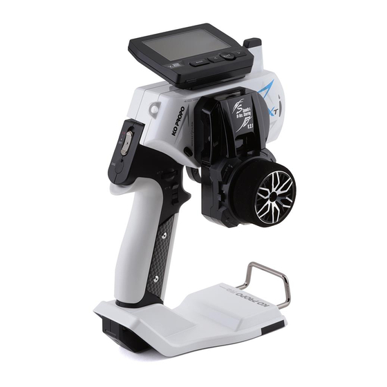
■ Specifications ■ Specifications EX-NEXT ■ Transmitter : KT-820H Control Type : Steering Wheel + Throttle Trigger Number of the channnel : 8 Power souce : R03/AAA/UM4 battery x4 Current : less 200mA Modulation : FHSS-XT Frequency : 2.4GHz Dimension : 240.5 x 163.0 x 107.2mm (Normal Grip) 256.0 x 170.0 x 127.5mm (LDT)
Need help?
Do you have a question about the EX-NEXT and is the answer not in the manual?
Questions and answers