Pima FORCE Installation Manual
Advanced security system
Hide thumbs
Also See for FORCE:
- Programming manual (40 pages) ,
- User manual (36 pages) ,
- Installation manual (48 pages)

Related Manuals for Pima FORCE


Summary of Contents for Pima FORCE
- Page 1 FORCE Advanced Security System Installation Guide System Version: Beta PIMA Electronic Systems Ltd.
- Page 2 Force Security System - Installation Guide...
-
Page 3: Table Of Contents
Table of Contents Table of Contents Chap. 1 Introduction ................7 Main features ................... 7 Technical specs ..................7 Chap. 2 Installation & Wiring ..............8 Location guidelines ..................8 Mounting the rack ..................8 The control panel ..................9 Connecting expanders and peripherals ............ - Page 4 Force Security System - Installation Guide Multiple to Multiple ................... 30 Partitions Names ..................30 Chap. 7 Outputs ..................31 Onboard ....................31 Zone Expanders ..................32 Output Expander ..................32 Chap. 8 CMS & Communications ............. 33 Monitoring Stations .................. 33 8.1.1...
- Page 5 Table of Contents Figure 17. KBH500 connection diagram ................19 Figure 18. GSM add-on front side .................. 20 Figure 19. GSM add-on back side .................. 20 Figure 20. The GSM add-on installed onboard ..............20...
- Page 6 Force Security System - Installation Guide Safety Instructions. Read Carefully The Force security system has been registered in accordance with EN60950 and its rules. Among other things, EN60950 requires us to advise you the following information: Hazards of fire and electric shock exist in this alarm system. To reduce the risk of fire or electric shock, do not expose this alarm system to rain or moisture.
-
Page 7: Chap. 1 Introduction
Chap. 1 Introduction This guide will introduce you with the new, highly reliable FORCE security system. With its 7-line LCD and clear menu-driven display, FORCE is an intuitive easy to install and program system. The Technician and User subject menus make programming and navigating fast and easy. Help screens reduce the need to look in this guide on every servicing. -
Page 8: Chap. 2 Installation & Wiring
To make installation and servicing easy and efficient, the FORCE’s control panel, transformer and backup battery are mounted on a special rack. The rack is covered by a metal case. Use the following list as a guide to find a suitable location to install the FORCE security system: ... -
Page 9: The Control Panel
Chap. 2: Installation & Wiring Figure 1. The control panel’s rack Figure 2. The rack’s cover The control panel 4 5 6 Figure 3. The control panel Following is the list of the control panel’s terminals: Zone inputs Z1-Z8, detectors voltage (+)/(-) Tamper switches 1-2 inputs External/internal Sirens, (+)/(-) ALRM output (by default, switched to (-) at alarm) -
Page 10: Connecting Expanders And Peripherals
The BUS is a serial communication channel, used for exchanging data between the control panel and the peripherals. The protocol in use by the BUS is ForceBUS (PIMA proprietary). Use four 0.5mm (24 Gauge (AWG)) wires. The maximum BUS length is 500m, including all peripherals and keypads. -
Page 11: Zone Connection
Chap. 2: Installation & Wiring Zone connection Figure 5. No EOL Figure 6. One EOL Figure 7. Two EOLs 2.6.1 Zone doubling Zone Doubling allows you to double the eight onboard zones to 16. All doubled zones must be wired according to the diagram below. Note that you cannot use zone expanders when you double zones. -
Page 12: Connecting Sirens
Siren Figure 9. Sirens connection Connecting zones and outputs expanders PIMA’s product line includes zone and output expanders. All expanders interface with the BUS. Following is the expander’s list: ZEL508 Local 8-zone expander. The expander is installed beside the control panel and is connected using a special 4-wire cable. -
Page 13: Local 8-Zone Expansion Card, Zel508
2.9.2 Local 8-zone expansion card, ZEL508 The ZEL508 allows adding eight zone inputs to the FORCE security system, locally. The card is installed on the control panel’s rack, and interfaces with the BUS using the technician’s fast connector on the control panel (see below), using a special cable (supplied). -
Page 14: Setting The Expander's Id Number
Force Security System - Installation Guide Card location buzzer Supplied mounted in a standard plastic 19 X 13 cm box Size: 8.2 X 15cm Technical specs: 10-15V, 30mA in idle state, fuse: 0.9A To PS-2 Power Supply Expander’s ID... -
Page 15: The Leds
Communication fault 2.9.6 Location buzzer Each FORCE expansion card has a buzzer, which helps in locating the card on the premises. The buzzer is triggered together with the card’s relay output, when performing an output test (see Test and Diagnostics menu, on page 45). -
Page 16: Remote 8-Relay Outputs Expansion Card, Oex508
Force Security System - Installation Guide To PS-2 Power Supply Expander’s ID Dip Switch Tamper Switch 1 2 3 4 Box Mounting PO WER SUPPLY BOOT Hole To Control Panel Technician Tamper and other Jumper Keypad Peripherals (BUS) Relay #2... -
Page 17: Connecting Radio Transmitters, Trv/Tru-100
Figure 16. OEX508 connection diagram 2.10 Connecting radio transmitters, TRV/TRU-100 PIMA’s TRV-100 (VHF) and TRU-100 (UHF) long-range radio transmitters are used as main or backup communication path to the monitoring station (CMS). Each model can use two different frequencies within its transmitting range. -
Page 18: Connecting Tamper Switches
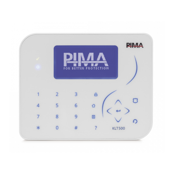
(see section 5.3, on page 27). 2.12.2 LCD keypads, KLT/KLR500 Main features Touch/rubber keys, 7-line LCD screen, 128x64 pixels display 4 operational LEDs Interfaces with the BUS and uses PIMA proprietary protocol Tamper switch protection... - Page 19 Chap. 2: Installation & Wiring Technical specs Powered by 13.8VDC, nominal Operating Voltage Range: +9 to +14 VDC Current consumption: Min.: 50mA (max.) Illuminating: 90mA Quick guide Type Status Indicates Arming Steady On System armed Away/all partitions armed System disarmed/all partitions disarmed Flashes once Exit delay in progress (in all or some partitions)
-
Page 20: Connect The Klt/Klr500 Keypads
The users can trigger three different alarms - panic, fire, and medical - by pressing and holding key combinations on the keypad. When these alarms are triggered, FORCE activates the programmed responses for such alarms, including triggering the sirens and reporting the CMS (where relevant) and contacts. -
Page 21: Gsm Add-On, Gsm501
2.13 GSM add-on, GSM501 The GSM add-on is used for transmitting reports and notifications from the FORCE to the CMS and the contacts, via cellular network. It is a Quad-band transceiver. An external antenna (long/short) can be used with the GSM501. -
Page 22: Add-On Installation And How To Replace The Sim Card
Force Security System - Installation Guide Network Modem Power Registration Antenna Base Onboard SIM Card Connector Holder Figure 19. Add-on’s front side Figure 20. Add-on’s back side GSM501 Onboard Socket Figure 21. The GSM add-on installed onboard 2.13.3 Add-on installation and how to replace the SIM card Disconnect AC and battery power before connecting the add-on. -
Page 23: Chap. 3 System Programming
Like all PIMA alarm systems, FORCE has two menus: User and Technician, each accessed with its own Master code. However, the FORCE has a new feature, in which a Central Monitoring Station (CMS) can have a separate communication settings lock code. -
Page 24: Changing The Master Technician Code
Zone and zone type definitions, copy zones. Outputs Control panel and expansion cards’ relay outputs. Communications CMS 1-2 definitions, PIMA cloud, and radio report codes. Faults System responses to faults and entering false code. General Settings System name, service provider, Master technician code, and other parameters. -
Page 25: Chap. 4 Installation Wizard
Chap. 4: Installation Wizard Chap. 4 Installation Wizard Parameter Description Default Range Time and Date The system time Entry Delay 1 A period of time that should allow disarming and entering the premises through delayed zones, and 30 sec 0-250 disarming the control panel, without triggering the alarm. -
Page 26: Chap. 5 Peripherals
Force Security System - Installation Guide Chap. 5 Peripherals Peripherals menu includes the following sub-menus: Zone Expanders: see below. Tampers & EOLs: see below. Keypads: set the no. of addressable keypads (ID 1-16). Keypad with ID no. 0 is not supervised, nor can it be partitioned. -
Page 27: Keypad Settings
Chap. 5: Peripherals Keypad Settings System Configuration Peripherals Keypad Settings Keypad Settings Press * or # to select a keypad. Note that the menu applies only for addressable keypads with ID no 1-16; keypad with ID=0 has no option for settings. Keypads menu includes the following sub-menus: Name: user text, up to 16 characters. -
Page 28: Chap. 6 Zones
Force Security System - Installation Guide Chap. 6 Zones Zones menu includes the following sub-menus: Zone Settings. See below. Zone Type Settings. See section 6.2, on page 29. Copy Zones. See section 6.3, on page 30. Partitions Names. See section 6.4, on page 30. -
Page 29: Zone Types Settings
Disarm and activate the external siren, even while the FORCE is at disarm. Reports at Reports to the CMS will be sent, even while the FORCE is at disarm. Disarm Auto-bypass If this zone triggers the alarm 3 times while the system is armed, the... -
Page 30: Copy Zones
Force Security System - Installation Guide Attribute When selected... Alarm Re- Selected: if the zone is still open at the end of the alarm time, the triggering zone will retrigger the alarm, continue to activate the sirens and will generate a new alarm report. -
Page 31: Chap. 7 Outputs
Chap. 7: Outputs Chap. 7 Outputs Outputs menu includes the following sub-menus: Onboard Outputs: see below. Zone Expanders: set the 8-zone and 16-zone expanders (ZEX508/516). There are up to 16 available outputs, depending on the overall number of expanders. See section 7.17.2. ... -
Page 32: Zone Expanders
Force Security System - Installation Guide Parameter Details Partitions Set the physical output’s allocation to partition/s - press the desired partition/s. The selected partitions will stay on and not flash. Press # or * to scroll between partitions. Name User text, up to 16 characters. -
Page 33: Chap. 8 Cms & Communications
Handshake signal for the selected protocol is not the first one sent by the CMS receiver. Range: 20-250 seconds. Central Monitoring Station Consult with PIMA support team regarding the functionality of the PID and SIA protocols... -
Page 34: Radio
Force Security System - Installation Guide Parameter Details Kissoff Wait: how long to wait for a Kissoff message, before resending the report. Change only if necessary, for example if there are delays in the communication. Range: 1-5000 milliseconds. ACK Frequency: select between Lo-Hi, 1400, 2300, and SIA. -
Page 35: Custom Zones Reports
Chap. 8: CMS & Communications b. A user un-bypass a zone Bypass Limit time elapses zone restore Following are several points regarding the reporting: zone restore report is generated when an alarmed zone is closed and rearms itself. When siren time elapses, the zone status is checked and if it has already been closed, the report is generated. -
Page 36: Pima Cloud
General Setting Parameter Details Remote Up/ Selected: remote upload/download via the FORCE Command software Download without the need for user permission is enabled. Not selected: remote upload/download is enabled only with user permission (see the User guide [P/N 4410460] for how to details) ... -
Page 37: Network Settings
Callback Address, Set an IP address and port no. for the control panel to send a connection Port request, in response to a request made by the FORCE Manager software. APN 1 Settings Name: user text, up to 16 characters. -
Page 38: Chap. 9 Faults
Force Security System - Installation Guide Chap. 9 Faults Faults menu includes the following sub-menus: AC Fault. See below. AC Loss Low Battery. See below. AC Loss Phone Line Fault. See below. AC Loss Network Fault. See below. -
Page 39: Chap. 10 Timers And Counters
Force Security System - Installation Guide Chap. 10 Timers and Counters Timers and Counters menu includes the system timers’ definitions. All times (except those otherwise mentioned) are in seconds. Parameter Description Default Range Programmed See next section. Output Types Entry Delay 1-2 A time period that allows entering the premises and disarming it (or a partition), without triggering an alarm. - Page 40 Force Security System - Installation Guide Parameter Description Default Range Siren beep The arming/disarming indication beep length 0-1000 mSec Report Delay AC Fault Phone Line Fault The delay time before transmitting a fault event. 120 min 0-250 GSM Fault ...
-
Page 41: Programmable Output Types
Force Security System - Installation Guide 10.1 Programmable Output Types System Configuration Timers and Counters Programmable Output Types Programmable Output Types , on page 50, for details on all the programmable output types. The default alarms and sirens programmable output types match the default zone types, and should not be changed in most installations. -
Page 42: Chap. 11 General Settings
Force Security System - Installation Guide Chap. 11 General Settings General Settings Following is the parameters of the menu: Parameter Details System Name Appears in contacts’ notifications. User text, up to 16 characters. Service Provider User text, up to 24 characters. The text is displayed when pressing and holding 0 (zero). -
Page 43: Arm Prevention - Faults
Chap. 11: General Settings 11.1 Arm Prevention - Faults System Configuration General Settings Arm Prevention - Faults You can prevent the users from arming the alarm system if some faults exist . Without fixing these faults the system cannot be armed. ... -
Page 44: Chap. 12 Reset To Defaults
12.1 Resetting to factory defaults If the Master technician code is unavailable, the FORCE can be reset to its factory defaults. To reset to the factory defaults, do the following: Disconnect the alarm system from AC and battery power for 5 seconds. -
Page 45: Chap. 13 Tests & Diagnostics
Chap. 13: Tests & Diagnostics Chap. 13 Tests & Diagnostics Tests & Diagnostics In the main screen, press . This menu includes the sub-menus that follows. Event Memory Zone Test. See below. Output Test Power Diagnostics ... -
Page 46: Power Diagnostics
13.5 Communication Tests The FORCE allows you to test each CMS defined communication path - telephone number, URL etc., by generating a Test report. During the test the display shows the online communication process - dialing, connecting, sending, etc. - Page 47 Appendix A Implementing Partitions FORCE allows defining up to 16 true partitions, whereby each can independently be in a different arming mode, i.e., Away, Home, or Disarmed. A partition is consist of several zones, and is normally a defined area, such as a building floor, a store or a compartment.
- Page 48 (see page 35). See the FORCE User guide on how the user approves the connection Upload/Download is done using the Force Manager software. Connection is made possible only if the Up/download code matches and the communication module is not at fault.
- Page 49 The control panel enters The user submits the pairing code to the technician. The code is valid for a few minutes only. The technician enters the code on the Force Manager and connects to the control panel Communication/ Connect by...
- Page 50 Force Security System - Installation Guide Appendix C Programmable Output Types Output Type Activation Deactivation Timer Partitioning Default 1-9998 9999 (sec) (Follower) (Latch) Alarms: Burglary, Panic, Alarm triggering Time elapses or disarming Silent panic, Fire, Medical, ...
- Page 51 Appendix C: Programmable Output Types Output Type Activation Deactivation Timer Partitioning Default 1-9998 9999 (sec) (Follower) (Latch) Code keystrokes Code Keystrokes counter Time elapses 24 key- exceeds limit strokes Zone Bypass programmed output type timer has special triggering definitions, as follows: 1-9998: the timer restarts each time a zone is bypassed 9999: the output type is active, as long as there is a bypassed zone 0: the output type is triggered when the first zone is bypassed and deactivates at disarm...
- Page 52 Appendix D Technician and CMS codes There are two technician codes in the FORCE security system: Master technician code, and CMS lock code, which allows limiting the access to the CMS menus by a password. Following is information on each code.
- Page 53 Appendix E: Text and Characters Appendix E Text and Characters Text is entered like in a telephone set: each key is allocated with several characters; each keystroke presents a different character. For example, press 8 twice to type U. The keystrokes and character table are described in the table and image that follow: Characters 1.,?!()/*:-+#@' ABC/abc2...
- Page 54 Force Security System - Installation Guide Appendix F CMS Event Reporting Below is a table with a list of the events that are reported to the CMS and private users. Event source/type Reporting Burglary Shock Sensor Burglary zone Alarm/Fault in...
- Page 55 Appendix G: Glossary Appendix G Glossary Cross Zones A false alarm reduction feature: two cross zones will trigger the alarm (separately), only if both Cross Zones are activated during the time. If only one cross zone is activated no alarm will occur. Cross Zones If the second (or any other) cross zone is activated after the time expired, no...
- Page 56 PIMA’s prior written consent is granted. All efforts have been made to ensure that the content of this manual is accurate. Pima retains the right to modify this manual or any part thereof, from time to time, without serving any prior notice of such modification.
Need help?
Do you have a question about the FORCE and is the answer not in the manual?
Questions and answers