Table of Contents
Advertisement
Quick Links
Advertisement
Table of Contents

Subscribe to Our Youtube Channel
Summary of Contents for Pima VISION
- Page 1 VISION Wireless Alarm System Installation Guide System Version: 1.x...
-
Page 2: Table Of Contents
VISION Installation Guide Table of Contents 1. Introduction ..................5 1.1. Main features ....................5 1.2. Alarm systems comparison table ..............6 1.3. Technical specifications................. 6 1.4. Ordering information ..................7 1.4.1. Kits ......................7 1.4.2. Alarm systems ..................7 1.4.3. - Page 3 RF transmissions will be attenuated by tinted glass, in wall isolation with metal foils, metal objects, etc. Safety Instructions. Read Carefully The VISION security system has been registered in accordance with EN60950 and its rules. Among other things, EN60950 requires us to advise you the following information: ...
- Page 4 VISION Installation Guide Default Codes Master User: 5555 Master Installer: 1234 Signs in this guide Warning Note...
-
Page 5: Introduction
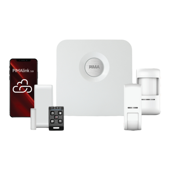
The VISION offers advanced communication technology, including built-in Ethernet connection. PSTN, cellular, and wi-fi communications are also optional. The VISION is initially programmed using a hardwired technician keypad, and by the PIMA Total Manager software remotely, afterwards. The PIMAlink 3.0 cloud service and smartphone application allow the end-user to receive notifications and control the alarm system from anywhere. -
Page 6: Alarm Systems Comparison Table
VISION Installation Guide 1.2. Alarm systems comparison table Feature VISION FORCE (wireless) (hardwired) Wireless zones (max.) Hardwired zones Wireless keypads Hardwired keypads Wireless expanders Communications: network, PSTN, wi-fi, and cellular. Radio Users Contacts Partitions Open collector outputs ... -
Page 7: Ordering Information
Introduction 1.4. Ordering information 1.4.1. Kits All kits includes the VISION alarms system, DPS187 PIR detector, DCM187 door contact, and RMC187 key fob. Product VCA187 Kit (868.95MHz) 8360101 VCD143 Kit (433.92MHz) 8360102 VCA143 Kit (433.92MHz) 8360103 1.4.2. Alarm systems Product Description P/N VCA143 (433.92 MHz) - Page 8 VISION Installation Guide Product Description Others Door contact 143: 8831002 187: 8831028 Key fob (black) 143: 8833008 187: 8833013 Panic button (white) 143: 8833006 187: 8833011 Arming Station 143: 8833002 187: 8833014 Siren ...
-
Page 9: Quick Guide
Quick guide QUICK GUIDE Figure 1. The control panel (VCD model (left), VCA model (right)) Following is a table of the control panel’s optional modules and sockets. Module/socket Description Wireless transceiver (onboard) Supplied in two frequencies: 433.92MHz, and 868.95MHz. Wi-fi module 2.4GHz, optional LEDs BUS indicators... - Page 10 VISION Installation Guide Module/socket Description Mounting hole PSTN module socket AC plug Power cord for VCA model Internal power supply VCA model Mounting hole + tamper knockout Tamper switch Cellular module socket Mounting hole...
-
Page 11: Installation
Installation INSTALLATION 3.1. Location guidelines Use the following list as a guide, to find a suitable location to install the VISION. Install the control panel in a protected location, where people cannot trip over any power cord. Select a location free from vibration and shock. -
Page 12: Figure 3. Mounting Holes
VISION Installation Guide Figure 3. Mounting holes Make sure to use the tamper’s knockout hole, for the control panel to alert when removed from the surface. 3. Pass the wiring through the opening and according to the designated surface, use appropriate wall plugs (if necessary) and screws, and mount the backplate. -
Page 13: Tamper Switch
Installation 3.3. Tamper switch The VISION’s control panel has a double-side tamper switch (marked with a circle in the image below), for detecting if the enclosure is removed from the mounting surface, or if its cover is being removed. Peripherals Tampers and ELOs Set the tamper in the menu. -
Page 14: Peripherals
VISION Installation Guide 3.5. Peripherals 3.5.1. PSTN module 1. Connect the PSTN module to its connector (see no. 17 in Figure 1, on page 9). 2. Connect the phone cords between the phone socket and the PSTN module’s Line IN terminals (or RJ11 socket). - Page 15 PIMA’s prior written consent is granted. All efforts have been made to ensure that the content of this manual is accurate. Pima retains the right to modify this manual or any part thereof, from time to time, without serving any prior notice of such modification.
- Page 16 P/N: 4410517 *4410517* Revision: A, XX en, Jun 2020...


Need help?
Do you have a question about the VISION and is the answer not in the manual?
Questions and answers