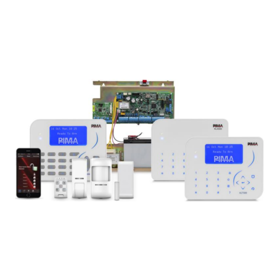
Pima FORCE Series Installation Manual
Advanced intruder alarm systems
Hide thumbs
Also See for FORCE Series:
- User manual (32 pages) ,
- Quick start manual (4 pages) ,
- Installation manual (22 pages)

Related Manuals for Pima FORCE Series


Summary of Contents for Pima FORCE Series
- Page 1 FORCE Series Advanced Intruder Alarm Systems Installation Guide System Version: 1.3.x...
-
Page 2: Table Of Contents
FORCE Series Installation Guide Table of Contents Introduction ..................5 Main features ....................5 System comparison table ................6 Technical specifications ................7 Ordering information ..................7 1.4.1 Peripherals .................... 7 The Control Panel ................9 Location guidelines ..................9 Installation .................... - Page 3 Figure 4. No EOL ..................11 Figure 5. One EOL ..................11 Figure 6. Two EOLs ..................11 Figure 7. Sirens connection diagram .............. 12 Figure 8. Line and Set connections ..............13 Figure 9. Event memory log ................. 37 PIMA Electronic Systems...
- Page 4 FORCE Series Installation Guide Safety Instructions. Read Carefully The FORCE security system has been registered in accordance with EN60950 and its rules. Among other things, EN60950 requires us to advise you the following information: Hazards of fire and electric shock exist in this alarm system. To reduce the risk of fire or electric shock, do not expose this alarm system to rain or moisture.
-
Page 5: Introduction
1: Introduction Introduction This guide will introduce you with the new hybrid, highly reliable FORCE Series (hereinafter, FORCE) intruder alarm systems, that includes the FORCE, the FORCE Lite and the FORCE 32. With 7-line, LCD screen, clear menu-driven display keypads, the FORCE is an intuitive, easy to install and use alarm system. -
Page 6: System Comparison Table
FORCE Series Installation Guide FORCE Lite Zones: eight onboard, expandable to 32, and 24 wireless (a total of 64, including double zoning). Users: up to 64, with a unique code for each, up to 24 of which with a remote control. -
Page 7: Technical Specifications
VHF Antenna 42cm: 6110003 VHF Antenna 51cm: 6110007 UHF Antenna: 6110004 CLM302 Cellular add-on (2G/3G) 8300045 CLM412 Cellular add-on (4G) 8300049 GSM501 Cellular add-on (2G) 8300040 GSM512 Cellular add-on (3G) 8300043 Wireless Frecuencias: 143: 433.92Mhz, 187:868.95Mhz PIMA Electronic Systems... - Page 8 FORCE Series Installation Guide Product Description PIR motion detector 143: 8831010 187: 8831024 PIR motion detector with pet immunity 143: 8831012 187: 8831025 143: 8831014 PIR motion curtain detector 187: 8831026 Gas detector 143: 8832004 ...
-
Page 9: The Control Panel
4. Connect the wiring. 5. Place the metal cover: tilt it upwards, insert the 2 tooth on the rack to the notches on the cover, place the cover on the rack and fasten the screw at the bottom. PIMA Electronic Systems... -
Page 10: The Control Panel's Circuit Board
FORCE Series Installation Guide Figure 1. The control panel’s rack Figure 2. The rack’s lid The control panel’s circuit board 3 4 5 Figure 3. The control panel’s circuit board diagram Following is a table of the circuit board’s terminals. -
Page 11: The Bus
The bus is a serial communication channel, used for exchanging data between the control panel and the peripherals. The protocol in use by the bus is ForceCom (PIMA proprietary). Use four 0.5mm (24 Gauge (AWG)) wires for the bus. The maximum bus length is 500m, including all peripherals and keypads. -
Page 12: Zone Doubling
FORCE Series Installation Guide 2.3.3 Zone doubling Zone Doubling allows you to double the eight onboard zones to 16. All doubled zones must be wired according to the diagram below. In the diagram on the right (all values are for example only), the zone Control Panel using the 10KΩ... -
Page 13: Relay
2. Connect phone set, fax machine or answering machine to the SET terminals - this will enable the control panel to answer any incoming call. Figure 8. Line and Set connections : not available FORCE L PIMA Electronic Systems... -
Page 14: System Programming
System Programming Menus and codes Like all PIMA alarm systems, FORCE has two menus: User, and Technician, each accessed with its own Master code. In addition, a new Central Monitoring Station (CMS) menu can have a separate communication settings lock code. -
Page 15: The Technician Menu
Zone and zone type definitions, copy zones. Outputs Control panel and expanders’ relay outputs. CMS & Communications CMS 1-2 definitions, PIMA cloud, and radio report codes. Faults System responses to faults and entering false code. Timers & Counters Programmable output types and other timers ... -
Page 16: Peripherals
FORCE Series Installation Guide Peripherals Peripherals menu includes the following sub-menus: Zone Expanders: see below. Tampers and EOLs: see below. Keypads: set the no. of addressable keypads (ID=1-16; FORCE Lite/32: ID=1-8). Keypad with ID=0 is not supervised, nor can it be partitioned. -
Page 17: Keypad Settings
When using the additional zone of the door contact, the first zone must be enrolled, even if it is not going to be used. After enrolling the two zones, the first zone can be deleted and re-used. PIMA Electronic Systems... - Page 18 FORCE Series Installation Guide Parameter Description Enrollment-Any Event 2) Auto: activate the detector; see above. Status: the system is waiting for a signal, or displays the received detector. Enroll: press to enroll the detector, or if multiple detectors are...
- Page 19 Press to delete the selected arming station. Delete Delete All: Press to delete all the defined arming stations. Settings Partitions: for each arming station, select its partitions. Name: user text, up to 28 characters. PIMA Electronic Systems...
-
Page 20: Zones
FORCE Series Installation Guide Zones Zones menu includes the following sub-menus: Zone Settings; see below. Zone Type Settings; see section 6), on page 21. Copy Zones; see section 5.3, on page 22. Partitions Names; see section 5.3.2, on page 22. -
Page 21: Zone Types Settings
If this zone triggers the alarm 3 times while the system is armed, the Zone Bypass zone is automatically bypassed (a report is generated) Auto-bypass Limit until the system/partition is disarmed, or until the time elapses; see 9, on page 32. PIMA Electronic Systems... -
Page 22: Copy Zones
FORCE Series Installation Guide Attribute Description Different Siren A different tone will be sounded when this zone triggers the alarm Tone Alarm Re- Selected: if the zone is still open at the end of the alarm time, the... -
Page 23: Outputs
Checked: the C and NC terminals are normally shorted. When activated, the C and NO terminals are shorted. Cleared: the C and NO terminals are normally shorted; C and NC terminals are shorted when activated. PIMA Electronic Systems... -
Page 24: The Ext./Int. Siren Outputs
FORCE Series Installation Guide Parameter Description Partitions Set the physical output’s allocation to partition/s - press the desired partition/s. The selected partitions will stay on and not flash. Press # or * to scroll between partitions. Name User text, up to 16 characters. -
Page 25: Cms & Communications
ContactID are: ContactID, SIA , and NPAF. System ID A parameter required by the NPAF protocol only. Consult the CMS. Central Monitoring Station Consult with PIMA support team regarding the functionality of the PID and SIA protocols PIMA Electronic Systems... - Page 26 FORCE Series Installation Guide Parameter Description Default Range ACKs Handshake Wait: how long the control panel will 20 sec. 20-250 sec. wait for a Handshake message, before disconnecting the call and redialing.. Range:. Kissoff Wait: how long the control panel will wait for 0 mS.
-
Page 27: Radio
Set event and restore codes for the following events: AC Fault, Low Battery, Power Loss, Detector’s Voltage Failure, Power: Fuse, Peripheral’s Power Fault Communication Fault, Telephone Line Fault, Cellular Communication: Fault, Network Fault External Siren Fault, Internal Siren Fault Sirens: PIMA Electronic Systems... -
Page 28: Custom Zones Reports
Only select one main path, or the communication with the cloud will be unstable! Do not change the default cloud URL, or the cloud service will be unavailable. Consult with PIMA first when it is required. PIMA Electronic Systems... -
Page 29: General Settings
Netmask, DNS, Default Set when using Gateway Callback Address, Port Set an IP address and port number for the FORCE Manager upload/ download software. These parameters are in the user menu, under Remote Service/Over Network : unavailable FORCE L PIMA Electronic Systems... -
Page 30: Cellular Settings
FORCE Series Installation Guide Cellular Settings System Configuration CMS & Communications Cellular Data Settings Parameter Description Installed Cellular Modem Select , if a modem is installed. Virtual Provider The SIM card’s provider is virtual. Network Settings Callback Address, above. -
Page 31: Faults
The report will be under the lowest partition number. CMS Comm., Tamper Open, Invalid Code, Other Faults Attributes : see section 5.2.1, on page 21. AC Fault Audible Notification: see above. PIMA Electronic Systems... -
Page 32: Timers And Counters
FORCE Series Installation Guide Timers and Counters Timers and Counters menu includes the following parameters. Parameter Description Default Range Programmable See next section. Output Types Entry Delay 1-2 A time period that allows entering the premises through 30/60 delayed and follower zones, and disarming it (or a sec. -
Page 33: Programmable Output Types
5 sec. Any Fault, AC Fault, Low Battery, Energy Saving 15 min Phone line/Net, Cellular Modem, 9999 Comm. Fault. Invalid Code keystrokes Tamper 240 sec. Operation Codes 1-8 5 sec. See Custom Zones Reports, on page 72. PIMA Electronic Systems... -
Page 34: General Settings
FORCE Series Installation Guide General Settings General Settings Following are the parameters of the menu: Parameter Description System Name User text, up to 16 characters. Service Provider User text, up to 24 characters. The text is displayed when pressing and holding 0 (zero). -
Page 35: Arming Prevention
AC Fault Low Battery Expander/Tamper Telephone Line Cellular them . The faults are: modem Network , and Select any fault to allow the user to override it. System Options/Faults Override In the user’s menu (user permission required). PIMA Electronic Systems... -
Page 36: Reset To Defaults
FORCE Series Installation Guide Reset to Defaults Reset to Defaults menu includes the following sub-menus: Select Parameters: select the parameters to be reset, from the following list: Communication Zones Outputs User Full System Reset - includes all the above. -
Page 37: Tests & Diagnostics
Description Keypad Buzzer The keypad’s buzzer will emit beeps on every detection External Siren Beep-External Siren will emit a beep on every detection Internal Siren Beep-Internal Siren will emit a beep on every detection PIMA Electronic Systems... -
Page 38: Output Test
Communication Tests CMS: test the CMS’s telephones, IP/URL’s etc., by generating a Test report. During the test the communication transactions are displayed onscreen. PIMA cloud: test the cloud’s IP/URL. Cellular signal: the signal strength in percents. 12.6 Communication Monitor ... -
Page 39: Appendix A. Implementing Partitions
4. A keypad can only display the status of and control the partitions it’s allocated to. The Armed LED stays on only when ALL the keypad’s partitions are armed, and flashes when only some partitions are armed. PIMA Electronic Systems... -
Page 40: Appendix B. Remote Up/Download
FORCE Series Installation Guide Appendix B. Remote Up/Download 1. User authorization Remote Up/Download CMS & Communication/General Settings The parameter under (see section 0, on page 34) sets if connecting remotely to FORCE for upload/download is enabled and if it requires a user approval. See the FORCE’s User guide on how the user approves the... -
Page 41: Appendix C. Programmable Output Types
Chime Activation Chime triggered Activation time elapses 3 sec Output-Key fob: output activation PIMA key fob: press the Activation time elapses, or by a keyfob Visonic key fob: press 5 sec ... -
Page 42: Appendix D. Technician And Cms Codes
FORCE Series Installation Guide Appendix D. Technician and CMS Codes There are two technician codes in the FORCE security system: Master, and CMS lock code, which allows limiting the access to the CMS menus by a password. 1. Master technician code By default, and as long as no CMS lock code (see next) has been set, the Master technician code enables to access all the technician menus, including all the CMSs’. -
Page 43: Appendix E. Text And Characters
The keystrokes and character table are described in the table and image that follow: Set 1 Set 2 Set 3 1.,?!()/*:-+#@' 1.,?!()/*:-+#@' 1.: abc2 ABC2 def3 DEF3 ghi4 GHI4 jkl5 JKL5 mno6 MNO6 pqrs7 PQRS7 tuv8 TUV8 wxyz9 WXYZ9 Space, 0 Delete, return to default Uppercase/lowercase/digits PIMA Electronic Systems... -
Page 44: Appendix F. Zone And System Status
Anti-mask alarm (wireless peripheral) Armed partition Zone test Supervision loss (wireless peripheral) 2. System status (main screen) Letter Indication Cellular data communication Network in use (including with PIMA cloud) Phone line in use Relay (device) activation Siren activation PIMA Electronic Systems... -
Page 45: Appendix G. Cms Event Reporting
Water leak Low gas pressure Restore High temperature Freeze Low temperature Restore Low water pressure Low water level When the report is delayed, if the fault doesn’t exist by the time the delay elapses, no report is sent. PIMA Electronic Systems... -
Page 46: Appendix H. Glossary
FORCE Series Installation Guide Appendix H. Glossary Cross Zones A false alarm reduction feature: two cross zones will trigger the alarm (separately), only if both Cross Zones are activated during the time. If only one cross zone is activated no alarm will occur. - Page 47 PIMA’s prior written consent is granted. All efforts have been made to ensure that the content of this manual is accurate. Pima retains the right to modify this manual or any part thereof, from time to time, without serving any prior notice of such modification.
- Page 48 P/N: 4410459 * 4 4 1 0 4 5 9 * Revision: B5, XX en, Dec 2019...
Need help?
Do you have a question about the FORCE Series and is the answer not in the manual?
Questions and answers