Pima HUNTER-PRO Series Installation Manual
Intruder alarm systems
Hide thumbs
Also See for HUNTER-PRO Series:
- Installation manual (112 pages) ,
- Installer programming manual (19 pages) ,
- Installation manual (116 pages)

Related Manuals for Pima HUNTER-PRO Series


Summary of Contents for Pima HUNTER-PRO Series
- Page 1 HUNTER-PRO SERIES NTRUDER LARM YSTEMS INSTALLATION GUIDE HUNTER-PRO 832, 896, 8144 , version 6.XX Expandable 8-144 zone...
-
Page 2: Table Of Contents
3.1.3 2-EOL resistor loop ........................14 Zone expanders wiring ..................... 14 3.2.1 Zone numbering ..........................15 3.2.2 Total number of expanders in Hunter-Pro Series .................15 Setting the expanders’ ID......................15 3.2.3 3.2.4 I/O-8N: remote 8 Zone expander ....................16 3.2.5 I/O-16: remote 16 Zone expander ....................18 3.2.6... - Page 3 Hunter-Pro Series Installation Guide CH. 4. INITIALIZING THE KEYPAD ..................35 Setting time & date (User menu) ..................35 4.1.1 The memory log ..........................35 CH. 5. PROGRAMMING OPTIONS ..................36 The PRG-896 programmer ....................36 Local programming via the COMAX application ..............36 Remote Programming via the COMAX application ............
- Page 4 Hunter-Pro Series Installation Guide 6.7.9 Bypass Limit Time .........................62 6.7.10 False code .............................62 6.7.11 Inactivity report ..........................62 Key #5: General Parameters ..................62 6.8.1 First screen ...........................62 6.8.2 Second screen ..........................63 6.8.3 Third screen ..........................64 Key #6: System Responses ................... 64 Key #7: Outputs configuration ..................
- Page 5 Formats & Codes ......................87 9.4.1 Pulse (4-2) .............................87 9.4.2 DTMF (4-2) ............................87 CH. 10. SUPPLEMENTARY PRODUCTS FOR THE HUNTER-PRO SERIES ......88 CH. 11. SYSTEM DEFAULTS ....................89 INDEX ............................ 98 TABLE OF DIAGRAMS ......................98 Factory default codes...
- Page 6 Hunter-Pro Series Installation Guide Quick Reference Press for 2 seconds, enter Press the key for 2 seconds to... User code and press the key to... ON/OFF Arm to full mode, disarm Quickly arm to full mode Display the log...
-
Page 7: Ch. 1. Introduction
Hunter-Pro Series Installation Guide CH. 1. INTRODUCTION This guide provides the installation, wiring and programming instructions for PIMA’s intruder alarm series, Hunter-Pro 832, 896 & 8144 models. The HUNTER-PRO series is secured against radio-frequency (RF) interferences and electro- magnetic interferences (EMI). -
Page 8: Version 6.33 Updates
Hunter-Pro Series Installation Guide Version 6.33 updates No. Feature Description Hardware Battery jump-start The control panel can be powered up only by AC power. See section 2 .2 Battery tests The test are suspended when the alarm is sounded... -
Page 9: Safety Instructions
Hunter-Pro Series Installation Guide Module/Accessory Details EXP UNIV 12VDC 10mA rms net4pro 12VDC 100mA rms net4pro-i 12VDC 70mA rms OUT-1000 12VDC 15mA rms IO-WN 13VDC 100mA rms GSM-200 13.8VDC 250mA rms MIC-200 12VDC 5mA rms VU-20U 12VDC 45mA rms RXN-400/410 13.8VDC 15-20mA rms... -
Page 10: Ch. 2. The Control Panel
Hunter-Pro Series Installation Guide CH. 2. THE CONTROL PANEL Diagram 1. The PCB Terminal Description/Connected accessories ZONES Z1-Z8 8 inputs for dry contact detectors. All loops can have one or two EOL (End-Of-Line) resistors. (+V)/(-)/AGND “+”: Detectors’ 12VDC power supply ... - Page 11 Earth ground terminal. Can be used in areas of severe electrical activity (abnormal levels of lightning or electrical discharge). When using PIMA’s integrated transformer, earth ground is not required. Only when using external transformer and lightning conditions are severe, the EGND terminal can be used.
-
Page 12: Current Limit Thermal Fuses
Hunter-Pro Series Installation Guide Current limit thermal fuses F1: Detectors (750mA); F2, F3: Siren #1 and #2 (0.9A); F4: Keypads (750mA); F7: Battery charger protection (200mA); F5: PCB and battery high current Thermo-fuse (5A/250VAC) protection;... -
Page 13: Ch. 3. Connecting And Wiring
Hunter-Pro Series Installation Guide CH. 3. CONNECTING AND WIRING (IN) (OUT) Diagram 2. System wiring diagram PIMA Electronic Systems Ltd. -
Page 14: Connecting Zones
The overall length of the BUS wires cannot exceed 500 meters. If a longer distance is required, refer to section 3 .2.7. The BUS uses PIMA proprietary protocol. IMPORTANT! Disconnect all power supply prior to installation! 3.1.1 Common zone wiring Diagram 3. -
Page 15: Zone Numbering
Zone numbering Hardwire zones come before wireless zones. Local expanders come before any other expander. The expanders are numbered in ascending order, according to their ID number. 3.2.2 Total number of expanders in Hunter-Pro Series 8144 I/O-8N 3 (2)* 11 (10)*... -
Page 16: I/O-8N: Remote 8 Zone Expander
Hunter-Pro Series Installation Guide 3.2.4 I/O-8N: remote 8 Zone expander 1 2 3 4 (OUT) (IN) 1 2 3 4 BUFFER Diagram 5. I/O-8N zone expander PIMA Electronic Systems Ltd. - Page 17 Hunter-Pro Series Installation Guide 3.2.4.1 I/O-8N & 16 LEDs Status Description Power ON (GREEN( Power fault MASTER Flashes Normal mode (DATA transfer) DATA (RED( Comm. disconnection Comm. short FAIL (RED) Flashes once a second DATA error Flashes 2 times a second Comm.
-
Page 18: I/O-16: Remote 16 Zone Expander
Hunter-Pro Series Installation Guide 3.2.5 I/O-16: remote 16 Zone expander + + + + 1 2 3 4 (OUT) (IN) 1 2 3 4 BUFFER Diagram 7. I/O-16 zone expander PIMA Electronic Systems Ltd. -
Page 19: I/O-R: Remote 8 Relay Expander
Hunter-Pro Series Installation Guide 3.2.6 I/O-R: remote 8 Relay expander + + + + 1 2 3 4 ) - ( (OUT) (IN) 1 2 3 4 BUFFER Diagram 8. I/O-R relay expander PIMA Electronic Systems Ltd. -
Page 20: The Bus Length
Hunter-Pro Series Installation Guide 3.2.7 The BUS length The BUS wire harness is connected to the KEYPAD 1-4 terminals on the control panel. The control panel can support a BUS that is no longer than 500m, including the connection of each and every expansion card, module and keypad. -
Page 21: I/O-Wn
Hunter-Pro Series Installation Guide 3.2.8 I/O-WN The I/O-WN is an integrated wireless module for adding wireless zones. See section 6 .3.3 for more details. The module connects to the panel over the BUS wires. Control panel 1 2 3 4... -
Page 22: Wireless Faults On The Display
Hunter-Pro Series Installation Guide Status Description Wireless signal has not been acquired VALID (GREEN) Wireless signal has been acquired No valid frame from the panel No ACK from the panel FAIL The expander is not programmed in the panel (RED) -
Page 23: Zone Doubling
Hunter-Pro Series Installation Guide 3.2.10 Zone doubling The 8 onboard zone terminals can be used to connect 8 more zone inputs, to include 16 zones in total, without using any expansion card. Zone doubling can only be used if no expander is in connected. -
Page 24: Key Input And Key Zones
Hunter-Pro Series Installation Guide KEY input and Key zones The KEY terminal serves as an input for key switches or key fobs. Connect the switch/key fob between the KEY terminal and GND (-). Starting system version 6.23, three new zone types were added: ... -
Page 25: Fsk" W/L Key Fob Receiver
Relays can be activated when the alarm is set off or a fault occurs, or when a relay code is entered (refer to the Hunter-Pro Series User manual) via one of the keypads or by telephone. To program the relay trip time, refer to section 6 .7.2. -
Page 26: Keypad Wiring
Hunter-Pro Series Installation Guide KEYPAD wiring Together with the zone expanders, keypads are wired through the BUS wire braid. The BUS (+) wire must be separated from all other (+) wires, e.g., the zones’ (+)! Up to 8 keypads can be connected to the Hunter-Pro system, supervised or not. -
Page 27: Tmpr1/Tmpr2 Wiring
Hunter-Pro Series Installation Guide 3.6.2.1 RXN-416 LED Keypad ID To set the keypad’s ID, follow the instructions in the previous section. The top screen LEDs will show the keypad’s ID according to the ID number (1-8), as follows: TMPR1/TMPR2 wiring Connect tamper switches between the TMPR1/TMPR2 terminals and ground (-). -
Page 28: Telephone Line/Set Wiring
Hunter-Pro Series Installation Guide Control Panel RXN-9 Diagram 19. RXN-9 PCB Telephone LINE/SET wiring Connect the telephone line directly to the LINE terminals. This will give the control panel priority when initiating a phone call. Connect telephone sets, answering machine, etc to the SET terminals. When the control panel initiate a phone call (or receive one), these terminals are disconnected. -
Page 29: Vu-20U Voice Message Module
Hunter-Pro Series Installation Guide MIC-200 MIC-200 CONT Control Panel Tamper switch (-)12(+) CON OUT TAMP Diagram 21. MIC-200 wiring 3.9.2 VU-20U Voice message module 3.9.2.1 Single message programming To use the VU-20U for a single message: Connect the Green wire (M1) to any output (including in zone expanders) that is set to be triggered by the ‘Audio device’... - Page 30 Hunter-Pro Series Installation Guide To set a single message: First, choose the triggering output and set its polarity to negative. “Audio Control” should be the default output type for the VU-20U. You can change it by pressing [NEXT] and select another one.
- Page 31 Hunter-Pro Series Installation Guide AUDIO IN Control panel M1: to the first output M2: to the second output VU-20U Diagram 23. VU-20U two message wiring To set the messages: 1. Select the triggering outputs and set their polarity to negative. See the first step in the previous section.
-
Page 32: Sms-100
Hunter-Pro Series Installation Guide SMS-100 Control Panel P1-Yellow AUDIO IN P2-Orange AUDIO OUT 3.9.4 GSM-200 cellular module The GSM-200 cellular module can serve both as a main or backup channel. The module can be used for reporting the end user. -
Page 33: Vvr: Video Verification Module
As many as 4 VVR units with 4 cameras in each, can be connected to the Hunter-Pro Series. The VVR and the cameras can be operated based on partition system, in which zones that are violated, trigger the camera that is allocated to the same partition they are allocated to. -
Page 34: 3.10 Backup Battery
Hunter-Pro Series Installation Guide The use of the VKD4net requires either a static (fixed) IP address on both the control panel and the remote PC, or a URL supplied by a DDNS service. In both ways, the routers must be set to enable port forwarding. -
Page 35: Ch. 4. Initializing The Keypad
Hunter-Pro Series Installation Guide CH. 4. INITIALIZING THE KEYPAD When AC power is supplied to the control panel, the keypad starts its initializing process: Keypad Ver. 1.15 Starting JAN 11 00:00 ..Keypad ID: 0 Please Wait... -
Page 36: Ch. 5. Programming Options
The fast programmer enables the installer to save time on-site, by uploading the presets before installation and use them for other installations too. The presets are uploaded via the Comax application. The PRG-896 is connected to any PIMA LCD keypad. See the next figure and section 6 .11.3. Keypad PRG-896 Diagram 29. -
Page 37: Remote Programming Via The Comax Application
1221 Express Programming menu To make common installation as easy and quick as possible, the Hunter-Pro Series includes a special menu - the Express Programming menu. It is a series of screens, taken from different parts of the Installer menu, with the necessary parameters for a common installation. - Page 38 Hunter-Pro Series Installation Guide Screen Description Hour Set the time 00:00 Month Year Set the date Priv.Phn 1<Del=# Set the 4 private dialer numbers. Use the asterisk key for ‘+’, ….. ‘*‘, ‘#’, ‘P’ (one second pause) ounters Entry/Exit Delay ENTR Priv.Phn 4<Del=#...
-
Page 39: Ch. 6. Programming The System
Hunter-Pro Series Installation Guide CH. 6. PROGRAMMING THE SYSTEM The Installer Menu Installer Installer Menu Choose 1,2.. code To enter the Installer menu: The Installer menu is made of 12 sub-menus, all accessed and programmed with the LCD keypad keys. -
Page 40: Key #1: System Installation
Hunter-Pro Series Installation Guide Keystrokes 3 4 5 6 7 8 9 10 / * : - + # & @ [#] Enable/Disable Cancel/ Return to previous [END] [BACK] Prev. char. screen/s without saving [NEXT] Next characters [ENTR] Select/Save Key #1: System installation 6.3.1... -
Page 41: Wireless Expander Setup
Hunter-Pro Series Installation Guide Par. Name Enabling (setting to “+”) Wireless Expander I/O-WN wireless receiver is installed and is monitored (see the next note). Key fobs are Visonic's. Key fob Receiver Not in use Enabling both ‘W’ & ‘R’ is not applicable 6.3.2.2 Remote Expanders... -
Page 42: Keypads
Hunter-Pro Series Installation Guide 6.3.3.2 Deleting a Wireless Zone Wireless Setup Delete Zone? ENTR NEXT ENTR NEXT ENTER/NEXT/END ENTER/NEXT/END Enter a zone ..Delete Zone? Device Deleted ENTR ENTR number Please Wait... Press END 6.3.3.3 Supervision interval ... -
Page 43: I/O-R Expander Settings
Hunter-Pro Series Installation Guide KPD 6 partitions ----++++-------- Example: keypad #6 will control the zones in partitions 5-8. 1 2 3 4 5 6 7 8 9 10 11 12 13 14 15 16 6.3.5 I/O-R expander settings Set the number of I/O-R relay expanders that are connected to the system. -
Page 44: Zone Responses
Hunter-Pro Series Installation Guide Par. Text When the character is enabled (set to “+”) Zone Follower As long as any delayed zone is still “open”, the zone will not sound the alarm during the entry delay, if violated. Second Delay Time If this zone is entry delayed zone (“I”... -
Page 45: Sensitivity
Hunter-Pro Series Installation Guide 6.4.3 Sensitivity S e n s i t i v . ( X 5 0 m S ) Set the zone sensitivity in milliseconds. Sensitivity is the time a zone must be violated, for the panel to identify it as a zone violation. -
Page 46: Partition Name
Hunter-Pro Series Installation Guide 6.4.6 Partition name Zones Partition Name ENTR NEXT ENTER/NEXT/END ENTER/NEXT/END Partition1 Name ENTR Partition To display the partitions and their names: Display Type: Master BACK ENTR Code Show Part Name Partition’s name can only be displayed in partitioned keypads. -
Page 47: Key #3: Communication
Hunter-Pro Series Installation Guide Key #3: Communication 6.5.1 Monitoring Station #1 options Communication MS 1 Options MS 1 Protocol ENTR ENTR ENTER/NEXT/END ENTER/NEXT/END 230 T=0 AA12PFDMOLTWIR SSBB Test Time: 00:00 ENTR ENTR ENTR +-+++++-+----- 1 --+- Rprt 1 Interval:24 Radio Tst Inter. -
Page 48: Account Numbers
Hunter-Pro Series Installation Guide 6.5.1.4 Telephone testing time, interval Set the time and interval for sending test reports to the Central Monitoring Station via the telephone. If left as 00:00 the panel ignores the “Time” parameter. The timer starts running only when pressing [ENTR] Test Time: 23:00 No. -
Page 49: Communication Options
Hunter-Pro Series Installation Guide In the “Communication Options” (next), when “Split Account No.” is enabled, “MS Phone #1” & #2 are allocated to Monitoring Station #1 and #3 & #4 to Monitoring Station #2. If the Monitoring Station’s telephone #1 is not answered, the panel tries to call number #2 and so on, up to 8 dialing attempts per number. - Page 50 Hunter-Pro Series Installation Guide Par. Description When enabled (set to ‘+’) Rem. Disarm Disab Remote disarming by the touch-tone telephone is disabled The panel reports when the Entry delay is starting (so if an intruder Pre Alarm Report cuts off the panel before the delay ends, the monitoring station is...
-
Page 51: Reporting Codes In 4X2 Format
Hunter-Pro Series Installation Guide 6.5.5 Reporting codes in 4X2 format Communication Report Codes 4X2 ENTR NEXT ENTR ENTER/NEXT/END ENTER/NEXT/END Zones Zones Restore General Reports NEXT NEXT ENTER/NEXT/END ENTER/NEXT/END ENTER/NEXT/END ENTR ENTR ENTR :FF Z2 :FF R2 ZFL:FF RESTR:FF :FF Z4... -
Page 52: Gsm Transmitter
Hunter-Pro Series Installation Guide Code Details FUS + RESTR Fail unsafe: detectors’ voltage fault + the restore System has been armed DISAR System has been disarmed System has been tested (manually, automatically, or “wake-up”). 6.5.6 GSM Transmitter The following menus are available only if the “Enhanced Menu” is enabled (see section ... -
Page 53: Sms Settings
Hunter-Pro Series Installation Guide 6.5.6.2 GSM Modes GSM Modes GSM-200 Mode 1 ENTR ENTR NEXT ENTR NEXT Voice Channel ENTER/NEXT/END GSM-200 Mode 1 GSM-200 Mode 1 GSM-200 Mode 1 NEXT NEXT NEXT Data Channel GPRS Channel SMS Channel The GSM-200 has two operation modes, for two Monitoring Stations: Mode 1 for MS #1 and Mode 2 for MS #2. -
Page 54: Serial Output
ENTR ____ Seconds Set the serial communication to the Central Monitoring Station. PIMA proprietary protocol can be used for Home Automation and Building Management monitoring. Par. Name Set to “+” if.. Home Automat. 1 MS1 uses Home Automation or Building Management protocol Network MS MS1 uses PIMA’s proprietary protocol... -
Page 55: Modem Call Back
In this example, Central Monitoring Station #2 can be located anywhere. Reports to Central Monitoring Station #1 (IP #1) are sent over IP in PIMA network protocol for central station; reports to Central Station #2 (IP #2) are sent the same way, but in Building Management/Home Automation protocol. -
Page 56: Ms2 Options
Hunter-Pro Series Installation Guide Par. Report Any alarm Anti-mask alarms Special Burglary 1 alarms Special Burglary 2 alarms Panic alarms Fire alarms Duress alarms Medical alarms Open/Close* Failure reports * This parameter is in use only for SMS reports: when it is enabled, arming/disarming by any code other than a user code - Master, Short, etc. -
Page 57: Advanced Programming
Hunter-Pro Series Installation Guide Advanced Programming Communication Advanced Prog. ENTR BACK ENTR ENTER/NEXT/END ENTER/NEXT/END Choose Provider Cell. Providers NEXT NEXT ENTER/NEXT/END ENTER/NEXT/END PSTN SMS Phones PSTN SMS Phones Network Settings NEXT ENTER/NEXT/END ENTER/NEXT/END ENTER/NEXT/END The advanced programming menu contains the programming of the cellular providers, the SMS settings and the network settings. -
Page 58: The Pstn Sms Center Phones
Hunter-Pro Series Installation Guide Screen Provider X information User… 1 Enter the username for the service. If the text is longer than 16 characters, press [ENTR] and continue to the next screen. User 1 Continue from previous screen Password… 1 Enter the password for the service. -
Page 59: Key #4: Timers, Counters
Hunter-Pro Series Installation Guide For static IP, fill in the address. To use DHCP, leave the static IP’s zeros. The panel will ignore the 3 following screens. MS1 & 2 URL/IP and Port screens are mandatory, both when using static or dynamic IP. See the next table for further details. -
Page 60: Entry & Exit Delay
Hunter-Pro Series Installation Guide 6.7.1 Entry & Exit delay Timers, Counters Entry/Exit Delay Entry 1 Exit ENTR ENTR ENTER/NEXT/END ENTER/NEXT/END Set the entry delays #1 and #2 and the exit delay in seconds (max. 250). Press [NEXT] to set the next parameter. -
Page 61: Ac Report Delay
Zone Open Hold** 0 (min.) * The time span that a physical output, triggered by phone (only in Hunter-pro Series), remains so. ** A timer that starts running when all the zones are closed. It can be used for energy saving, by turning off (using a Relay) the light, for example, when the premises is not occupied anymore. -
Page 62: Conditioned Zones Time
Hunter-Pro Series Installation Guide 6.7.8 Conditioned zones time Set the time (in seconds) for two (or more) conditioned zones to sound the alarm, if both are violated within it. See also section 6 .4. 6.7.9 Bypass Limit Time Set a time span (in minutes, max. 250) for any zone to be temporarily bypassed (when arming the panel). -
Page 63: Second Screen
Hunter-Pro Series Installation Guide Par. Name Setting to “+”… Open zones are bypassed, when auto-arming. Nevertheless, a Byps. Zone in Au. bypassed zone that is tripped, does trigger the alarm. 2 EOL Resistors All EOL loops have 2 resistors. The resistors’ value is set by the onboard jumper JP11. -
Page 64: 6.8.3 Third Screen
Hunter-Pro Series Installation Guide Par. Name When setting to “+”… Disp. Armed Part (+) Armed partitions are displayed in the Scan Open Zone displaying mode (together with any other information). (-) Armed partitions are not displayed, but can be momentarily displayed by pressing [#] in the Scan Open Zone displaying mode only. -
Page 65: 6.10 Key #7: Outputs Configuration
Hunter-Pro Series Installation Guide Par. Response When setting to “+” … Act. Burgl Output Alarms activate the Burglary output type No Daytime MS The panel does not report the Monitoring Station when it is disarmed Activate Buzzer Alarms activate the keypad buzzer 6.10 Key #7: Outputs configuration... -
Page 66: The Output Types
Hunter-Pro Series Installation Guide 6.10.2 The output types PCB’s output PCB’s output External Siren External Siren Output Configur. ENTR ENTR ENTER/NEXT/END ENTER/NEXT/END External Siren Output Type ..External Siren External Siren External Siren NEXT NEXT Burglary... -
Page 67: Outputs Partitions
Hunter-Pro Series Installation Guide Output type The triggering event Low Battery Low battery fault Phone Fault Phone fault GSM Fault GSM fault Communication Fault Communication fault Not In Use Door Code The Door code is entered Wireless Remote An output is activated by a remote control/key fob... -
Page 68: Outputs On Expanders
Hunter-Pro Series Installation Guide 6.10.6 Outputs on expanders 6.10.6.1 OUT-1000 OUT-1000 Outputs Output Configur. Output 1 ENTR NEXT ENTR ENTER/NEXT/END ENTER/NEXT/END ENTER/NEXT/END Physical output Part.for Out 1 Output 1 ENTR ENTR ENTR ++++++++++++++++ Fire Output type Configure the OUT-1000 (8 output expansion card) outputs. The screens are the same as those of the PCB outputs. - Page 69 Hunter-Pro Series Installation Guide The procedure is as follows: In the “Output Configuration” menu, press [NEXT] to the ON/OFF output screen; Press [ENTR]; Press [NEXT] to select the triggering output type. In this example, the ON/OFF output will be tripped every time one of the zones (subject to the partitions, where relevant) is opened;...
-
Page 70: 6.11 Key #8: Full Programming
Hunter-Pro Series Installation Guide 6.11 Key #8: Full programming 6.11.1 System defaults Reset the panel to the factory defaults. Full Programming System Defaults Are you sure? ENTR ENTR ENTR ENTER/NEXT/END ENTER/NEXT/END ENTER/NEXT/END Syst.Defaulted Defaulting ..Press END Please wait... -
Page 71: 6.12 Key #9: Installer Code
Hunter-Pro Series Installation Guide 6.12 Key #9: Installer code Installer Code Installer Code ENTR ENTER/NEXT/END ****** (4-6) Set/change the Installer code. The default Installer code must be replaced immediately after installation! The code can have up 4 - 6 digits. -
Page 72: Single Zone Test
Hunter-Pro Series Installation Guide To indicate by the sirens too, set to “+”: ”E”, for the external siren; the internal siren will be activated too. “I”, for the internal siren only. Untested Zones: All Zones Tested If all zones were successfully tested: . -
Page 73: Set Soak Zones
Hunter-Pro Series Installation Guide 6.14.4 Set soak zones Set Soak Zone Zone Number: 1 ENTR NEXT ENTR ENTR ENTER/NEXT/END Entr-Conf #-Rst Soak Zone Zone A zone that is suspected in causing false alarms, can be tested, by setting it as a soak zone. -
Page 74: Monitoring Station's Pstn Dialer Test
Hunter-Pro Series Installation Guide 6.14.6 Monitoring Station’s PSTN dialer test …. Test MS Dialer ENTR NEXT Select T.No. 1-4 Test the Monitoring Station’s PSTN numbers: press [1] to dial to telephone #1; press [2] to dial to telephone #2, and so on. -
Page 75: Video
2 modules in Hunter-Pro 832. Max. MMS per day Not in use Opening a delayed zone triggers the VVR to record a clip Not in use 1 Requires an SD card (not supplies by PIMA). PIMA Electronic Systems Ltd. -
Page 76: Camera Partitions
Hunter-Pro Series Installation Guide 6.15.2 Camera partitions Camera Partition Camera 1 Part ENTR NEXT ENTR ENTER/NET/END +--------------- ..Camera 16 Part ENTR +--------------- Allocate the cameras to partitions, so only some zones can trigger them. With regard to privacy, partitions can be used to limit zones and users from watching the video stream. -
Page 77: 7. Remote Control Via Touch-Tone Telephone
CH. 7. REMOTE CONTROL VIA TOUCH-TONE TELEPHONE The Hunter-Pro Series models can be remotely controlled via a touch-tone or cellular telephone. A remote control call can be initiated both by calling the panel or receiving a call from the panel. -
Page 78: Example For Basic Mode
Hunter-Pro Series Installation Guide Press a key according to the next table. The panel confirms every command by 2 beeps. Command Stop the external siren and the dialer Arm the panel Disarm the panel Arm the panel to ‘Home 1’ partial arming mode ... -
Page 79: Examples Of Full Control Mode
Hunter-Pro Series Installation Guide Relays on I/O-8N Expanders Dial I/O-8N Dial I/O-8N Dial I/O-8N I/O-R expander #1 I/O-R expander #2 Dial Relay Dial Relay Dial Relay Dial Relay I/O-R expander #3 I/O-R expander #4 Dial Relay Dial Relay Dial Relay... -
Page 80: Ch. 8. Partitions
There can be up to 16 partitions in Hunter-Pro Series. In addition to zone partitions, PIMA’s systems provide keypad partitions as well: monitored (addressable) keypads can be assigned to partitions and control (or display information about) only zones that are part of these partitions. -
Page 81: Diagram 35. Implementing Partitions - Example B
Hunter-Pro Series Installation Guide Example B: private premises, 3 keypads Diagram 35. Implementing partitions - Example B The system is divided into partitions, each controlled by a separate keypad. The users have authorization levels based on partition/s, e.g., user 12 can only control Partition #3 & #14. -
Page 82: Locating An Expander's Zone
Hunter-Pro Series Installation Guide Example D: office compound Diagram 37. Implementing partitions - Example D A compound is made of 16 offices; each is located in a separate room. Each room is assigned as a partition and can be controlled by different users, remote controls, key switches and RFID tags. -
Page 83: Ch. 9. Troubleshooting
The process is also useful for Installer code (Default code 1234), with the exception of a code that begins with zero. In this case the code cannot be reset and you need to call PIMA support Faults Displayed on the LCD Keypad In case a fault occurs, the red fault LED on the keypad flashes. - Page 84 Hunter-Pro Series Installation Guide Fault Description & Repair Zone Fault 1. F - Cut, S - Short (in EOL circuits). In fast display mode: FL- Cut, SH- Short 2. In wireless zones: detector’s tamper is open KEYPAD NOT No communication between the keypad and the PCB. Check the following: CONNECTED 1.
-
Page 85: Other Faults
Hunter-Pro Series Installation Guide Fault Description & Repair MS. Com. Fault Failure to communicate with the MS including in test mode. This fault appears if the HUNTER-PRO communicator cannot transfer reports to MS. Possible reasons are incompatible protocol or phone line failure. -
Page 86: Dialer
TAMPER 2: Tamper 2 is triggered. 9.3.6 Auto-Arming & Auto-Arming per Partition Make sure that: Auto-arming start time is programmed (see the HUNTER-PRO Series User guide). Auto-arming by inactivity time per partition is programmed. System time is correct. The desired partition is programmed as so. -
Page 87: Formats & Codes
Hunter-Pro Series Installation Guide The zone conditioning is correct. The zone number of pulses is correct. The zone is not programmed as a soak zone. Formats & Codes 9.4.1 Pulse (4-2) Name Rate (pps) ACK (Hz) Error Control Double Round... -
Page 88: 10. Supplementary Products For The Hunter-Pro Series
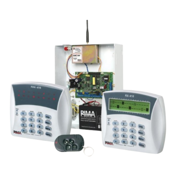
Hunter-Pro Series Installation Guide CH. 10. SUPPLEMENTARY PRODUCTS FOR THE HUNTER-PRO SERIES Led Keypads LCD Keypads RXN-416 – For 16 Zones RXN-9 – For 9 Zones RXN-400 - Small LCD Display RXN-410 - Large LCD Display RXN-400 ACE – LCD Display... -
Page 89: Ch. 11. System Defaults
HUNTER-PRO Series Installation Guide CH. 11. SYSTEM DEFAULTS... - Page 90 Hunter-Pro Series Installation Guide PIMA Electronic Systems Ltd.
- Page 91 Hunter-Pro Series Installation Guide PIMA Electronic Systems Ltd.
- Page 92 Hunter-Pro Series Installation Guide PIMA Electronic Systems Ltd.
- Page 93 Hunter-Pro Series Installation Guide PIMA Electronic Systems Ltd.
- Page 94 Hunter-Pro Series Installation Guide PIMA Electronic Systems Ltd.
- Page 95 Hunter-Pro Series Installation Guide PIMA Electronic Systems Ltd.
- Page 96 Hunter-Pro Series Installation Guide PIMA Electronic Systems Ltd.
- Page 97 Hunter-Pro Series Installation Guide PIMA Electronic Systems Ltd.
-
Page 98: Index
HUNTER-PRO Series Installation Guide INDEX Accessories: MIC-200, 28, 29, 44, 66, 78, 88; PRG- Accessories: MIC-200, 28, 29, 44, 66, 78, 88; PRG- 896, 36 896, 36 Comax, 36, 37, 49, 53, 70 Comax, 36, 37, 49, 53, 70 Expanders: EXP-PRO, 11, 14, 15, 23, 40, 88; I/O-16, Expanders: EXP-PRO, 11, 14, 15, 23, 40, 88;... - Page 99 PIMA’s prior written consent is granted. All efforts have been made to ensure that the content of this manual is accurate. Pima retains the right to modify this manual or any part thereof, from time to time, without serving any prior notice of such modification.
Need help?
Do you have a question about the HUNTER-PRO Series and is the answer not in the manual?
Questions and answers