Table of Contents
Advertisement
Quick Links
Advertisement
Table of Contents

Subscribe to Our Youtube Channel
Related Manuals for ADTEK MW-5


Summary of Contents for ADTEK MW-5
- Page 1 A-05-MW-5-OPERATING MANUAL-20120719...
-
Page 2: Table Of Contents
INDEX ■ DESCRIPTION ------------------------------------------------------------------------------------------- 1/34 ■ FEATURES ----------------------------------------------------------------------------------------------- 1/34 ■ APPLICATIONS ----------------------------------------------------------------------------------------- 1/34 FUNCTION DEFINE & DESCRIPTION ■ --------------------------------------------------------- 2/34 ■ Character Symbol ---------------------------------------------------------------------------------------------- 2/34 ■ Input Function --------------------------------------------------------------------------------------------------- 2/34 500V & 50A(with YMWH-CT10A) input directly Input Range(Voltage input / Current input) ■... -
Page 3: Description
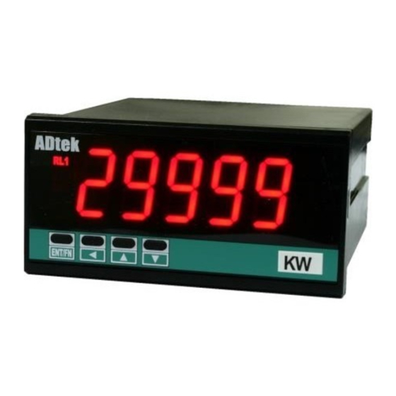
MW-5 ACTIVE POWER METER OPERATION MANUAL DESCRIPTIONS ■ MW-5 Active power meter is destined with high accuracy measurement, display, control and communication (Modbus RTU mode) with flexible functions and compact size(96Wx48Hx120D). The main purpose is for power management of equipment, machinery and consumption testing system. -
Page 4: Function Define & Description
Primary Current of CT: 1~9999.9A Please paste the sticker on the right side PV.H Secondary Current of CT:1.000~9.999A of green square LED of ECI to identify the status of ● Frequency: 50/60 Hz±3 Hz display. 2 / 36 MW-5 Operating Manual 2012-07-19... -
Page 5: Reading Stable Functions
[pVzro] & higher point for [pVspn]. The meter will 3reading, and calculating the average then update be linearization automotive for full scale. display. At meantime, the display update will be 15 times/sec. MW-5 Operating Manual 2012-07-19 3 / 36... -
Page 6: Digital Filter
Relay Functions ■ 1. To avoid alarm for the starting current of MW-5 series offer the 2 relay outputs with inductive motor(6 times of rated current). flexible and versatile functions. They can be 2. If the ry_.md relay energized mode has been set programmed individually in [relay group]。... -
Page 7: External Control Inputs(Eci)
Please refer to the figure as following, the below figures. PV Hold & Reset PV Hold Present Value Reset PV Hold [ e c I _ ] Level by E.C.I. or Trigger pVhld Front Key MW-5 Operating Manual 2012-07-19 5 / 36... -
Page 8: Rs485 Communication
0.00, [ aOhs]: 100.00 SCALE [ aOls]: 50.00, [ aOhs]: 19(99 Change to MW-5 supports Modbus RTU mode protocol to 19(99 be used as Remote Terminal Unit (RTU) for [ aOhs] monitoring and controlling in a SCADA (Supervisor Control And Data Acquisition) system. The baud 10)00 rate can be up to 38400 bps. -
Page 9: Installation
Herein, recommended that power supplied to the Max load 50A Fixing by meter with protection by a fuse or circuit breaker. Cable Tie 8 9 10 1A Fuse AC115/230V AC85~264V Filter or Transformer MW-5 Operating Manual 2012-07-19 7 / 36... - Page 10 ADH: AC85~264V External Control ADL: AC20~56V 1 2 3 4 5 6 7 8 9 10 DC100~300V Input DC20~56V AUX. POWER ECI1 ECI2 COM ADH: AC85~264V AC115V DC100~300V AC230V External Control Input AUX. POWER 8 / 36 MW-5 Operating Manual 2012-07-19...
- Page 11 Terminate Resistor (at latest unit): 120~300ohm/0.25W (typical: 150ohm) 1 Relay output + RS485 Communication Port Pulse Output Open Connect Output Relay Contact Output 1 Analogue output + RS485 Communication Max load 30V/60mA Port 15 16 MW-5 Operating Manual 2012-07-19 9 / 36...
-
Page 12: Operations
Key, the PV will show relative Reset fo Relay Latch value as like as terminals of ECI2 close. If the front key function has been set, the terminal input for ECI will be disabling. 10 / 36 MW-5 Operating Manual 2012-07-19... -
Page 13: Error Massage
(1) In Function Index Page, press (2) In setting status for function, press to select will go to the next Function function Down key Index Page. (3) During number Setting, press can roll the digit down. MW-5 Operating Manual 2012-07-19 11 / 36... -
Page 18: Operating Steps
FUNCTION DESCRIPTION PARAMETERS & SETTING SET Please check the specification and POWER wiring diagrams firstly. ***** Self-diagnosis (LED All bright) Model mw-5 mw-5: Active power meter ver!0 Firmware version ver!0: Version 1.0 3p3w System connection 3p3w: 3P3W 168*8 Measuring Page... -
Page 19: Programming Level
1 second to back Measuring Page RS485 INPUT RELAY EXTERNAL ANALOGUE GROUP CONTROL OUTPUT GROUP GROUP INPUT GROUP GROUP PRESS PRESS PRESS PRESS PRESS TO ACCESS TO ACCESS TO ACCESS TO ACCESS TO ACCESS MW-5 Operating Manual 2012-07-19 17 / 36... - Page 20 %000 %000 Wunit Wunit: Unit of Active power(Watt) Programmable: 1(W) / )01k(W) / )1k(W) / 1k(W) / )01m(W) / )1m(W) / )01m 1m(W) & Selection Enter Next Page 18 / 36 MW-5 Operating Manual 2012-07-19...
- Page 21 PV that it will compare with rs485(RS485): Remote set-point, analogue output and ECI displayed from RS485 functions so that is to control analogue command of master. output, relay energized and so on. & Selection Enter Next Page MW-5 Operating Manual 2012-07-19 19 / 36...
- Page 22 3 reading, and calculating the average then update display. At meantime, the display updated will be 15 times/sec. Next Page 20 / 36 MW-5 Operating Manual 2012-07-19...
- Page 23 Programming level lock. User can access to programming level for checking, but can not setting. all(All Level): All lock. User can access to all level for checking, but can not setting. & Selection Enter MW-5 Operating Manual 2012-07-19 21 / 36...
-
Page 24: Relay Group
E.C.I. closed rYrst by ECI or Front Key do(DO): Digital Output; Relay is energized by RS485 command directly, and no longer to compare with set-point of relay. & Selection Enter Next Page 22 / 36 MW-5 Operating Manual 2012-07-19... - Page 25 (rY2.rd): Relay 2 energized Settable range: ry@rd delay time 0:00.0~9(M):59.9(S) )0)0 )0)0 Shift Down Enter (5(9 ry@fd (rY2.Fd): Relay 2 de-energized Settable range: ry@fd delay time 0:00.0~9(M):59.9(S) )0)0 )0)0 Shift Down Enter (5(9 MW-5 Operating Manual 2012-07-19 23 / 36...
-
Page 26: External Control Input(E.c.i.) Group
Programmable: pVhld none / reLpv / pVhld / rYrst Mrst / rYrst / Down Enter debnc(dEbnc): Debouncing of Settable range: 5~255( x 8ms) debnc external control Input Shift Down Enter Next Page 24 / 36 MW-5 Operating Manual 2012-07-19... - Page 27 (4~20mA) is relative to display 0~199.99. 5)00 User can set the [aOls] (Ao.LS) to be [ aOls] 5)00. At meantime, the output signal will OUTPUT 0.00% 50.00% 100.00% be 4mA when the present value is 50.00. Next Page MW-5 Operating Manual 2012-07-19 25 / 36...
- Page 28 [ aOhs]: 15)00 (Display value High); [ hIsc] [ aOlmt]: 8)00%( of Output Range) 19(99 [ aOhs] Ao.LMt: 80.00% 15)00 10)00 [ aOls] 5)00 [ lOsc] OUTPUT 0.00% 50.00% 100.00% 80.00% [ aOlmt] 26 / 36 MW-5 Operating Manual 2012-07-19...
-
Page 29: Rs485 Group
9600 / 19200 / 38400 38400 & Selection Enter prity(PritY): Parity Programmable: prity NstB2 NstB1(n.Stb.1): None, 1 stop bit NstB2 NstB2(n.Stb.2): None, 2 stop bit even odd(odd): odd even(EvEn): Even & Selection Enter MW-5 Operating Manual 2012-07-19 27 / 36... -
Page 30: Trouble Shooting
C.Please check the unit and resolution of Active power [ Wunit](A-06) D.Please check the [pVzro](A-07) & [pVspn](A-08) in [input group] whether did correct or not? Recommented to clear the [pVspn] in [Sclr](A-09) first. 28 / 36 MW-5 Operating Manual 2012-07-19... - Page 31 A.Please check the product number and output(O/P:_____) of Relay for detail specification. description again for confirmation the relay output is specified dosen’t shown or not? B.Please send back to our sales window, or order another meter with relay function. MW-5 Operating Manual 2012-07-19 29 / 36...
- Page 32 As a general rule, wire connecting with the meter has to be in a separate system, use an independent metal conduit, or use shielded cable. RS485 Communication Issue: PROBLEM CHECKING LIST REMEDY 30 / 36 MW-5 Operating Manual 2012-07-19...
-
Page 33: Rs485 Modbus Rtu Mode
Address Hi Address Lo DATA Hi DATA Lo Response Data Frame SLAVE FUNCTION Starting Starting Preset Preset Address Code Address Hi Address Lo DATA Hi DATA Lo ADDRESS TABLE **Address number are Hexadecimal ■ MW-5 Operating Manual 2012-07-19 31 / 36... -
Page 34: User Level
Reserved 0024h 0025h Reserved rs485* 0026h -19999~99999 POWER(WATT) will be written in by RS485 *(High Word) rs485* 0027h POWER(WATT) will be written in by RS485 *(Low Word) Reserved 0028h Reserved 0029h 002Ah Reserved 32 / 36 MW-5 Operating Manual 2012-07-19... -
Page 35: Programming Level
2: Maximum Hold(maXhd) 3: RS485(rs485) lOcut 003Dh 0~10000 Low Cut of Power(Watt) 003Eh 1~99 Average display for Power(Watt) Dfilt 003Fh 0~99 Digital Filter for Power(Watt) 0040h Reserved Pcode 0041h 0000~9999 1000 Pass Code MW-5 Operating Manual 2012-07-19 33 / 36... -
Page 36: [Relay Group]
2: pVhld(PV Hold for Power); 3: Mrst (Reset for Maximum & Minimum); 4: rYrst (Reset for Relay Latch); 5: di (Digital Input); 6: (Option) bKsel(Bank selection) External Control Input 2 ecI2 0054h 0: none (None); 34 / 36 MW-5 Operating Manual 2012-07-19... -
Page 37: [Ao Group]
ADtek assumes no responsibility for any inaccuracies that may be contained in this document, and make no commitment to update or to keep current the information contained in this manual. ADtek reserves the right to make improvements to this document and/or product at any time without notice. - Page 38 Copyright © 2008 ADtek Instruments Co., Ltd. All rights reserved. Printed in Taiwan. Welcome to visit our online www.adtek.com.tw www.csec.com.tw 36 / 36 MW-5 Operating Manual 2012-07-19...
Need help?
Do you have a question about the MW-5 and is the answer not in the manual?
Questions and answers