Advertisement
Quick Links
Advertisement

Related Manuals for ADTEK CPM-20 Series


Summary of Contents for ADTEK CPM-20 Series
- Page 1 CPM-20 Power Analyzer CPM-21 MULTIFUNCTION POWER METER Rev 2.5 Rev 2.5 2023/12/15 2023/12/15...
-
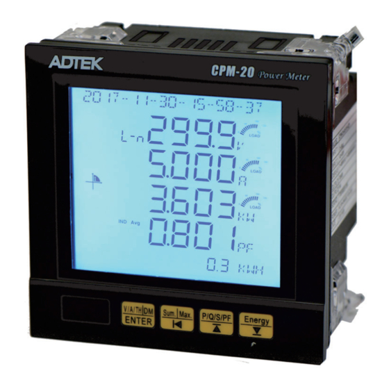
Page 2: Front Panel
CPM-21 Operation Manual DESCRIPTION The CPM-20 series Multifunction Power Meter provide high accuracy measurement, display and communication(Modbus RTU) of all electrical and power quality parameters, including harmonic measurement THD(Total Harmonic distortion 2nd~31st) Provides electricity bill ratio (Cost) and CO set can show cumulative electricity bills and carbon emissions, and suitable for the installation in the power management of remote communication, such as the use of demand. -
Page 3: Connection Diagram
Dimensions 90.0 +0 .8 90.0 +0 .8 55 5 . 15 0 . FIX HOLDERS User's Manual 1.0~18.0 mm Connection diagram 15161718 19202122 2324 1A Fuse AC85~264V EMC Filter RS485 Port 111213141516171819 Distance Max.: 1200M : 120~300 / 0.25W Ω Terminator : 150 ) Ω... - Page 4 3P3W NO PT 3CT(0~1A/5A) 2CT(0~1A/5A) 1CT(0~1A/5A) 3CT(0~333mV) 2CT(0~333mV) 1CT(0~333mV) 3P3W 2PT 3CT(0~1A/5A) 2CT(0~1A/5A) 1CT(0~1A/5A) 3CT(0~333mV) 2CT(0~333mV) 1CT(0~333mV)
- Page 5 3P4W NO PT 3CT(0~1A/5A) 1CT(0~1A/5A) 3CT(0~333mV) 1CT(0~333mV) 3P4W 3PT 3CT(0~1A/5A) 1CT(0~1A/5A) 3CT(0~333mV) 1CT(0~333mV)
- Page 6 Operational processes Key definition: ENTER / Volt.( )/AMP.( Voltage current Confirm wiring Shift:Shift left /Total(Comprehensive) Power transmission Up: Move Up /Power Down: Move Down /Energy Display Models and versions Press 1 Sec back operation display 2 0 1 2 0 7 - 0 3 - 1 3 - 5 0 - 4 0 2 0 1 2 0 7 - 0 3 - 1 3 - 5 0 - 4 0 Phase voltage and the Average Phase A voltage...
- Page 7 Press Press Voltage and Current harmonics screen Voltage and Current harmonics screen Normal screen 1 seconds, first showed off the voltage value As follows Phase voltage and the Average 1.1.4- Phase Current and Neutral Phase A voltage Current Phase A current Phase B voltage Phase B current Phase C voltage...
- Page 8 (3P3W/3P3W.B/3P3W3 No such function) (3P3W/3P3W.B/3P3W3 No such function) ress ress Power Parameters Power Parameters ress ress Shift Shift Comprehensive screen Comprehensive screen KEY( KEY( Normal screen 1 seconds, Normal screen 1 seconds, first showed off the voltage value As follows first showed off the voltage value As follows Phase voltage and the Average Phase voltage and the Average...
- Page 9 Press Press Down Down Power parameters Power parameters Normal screen 1 seconds, first showed off the voltage value As follows Press Phase voltage and the Average 1 3 5 . . - Phase A voltage Phase voltage angle ◎Additional screen display for V3.0 and above version Phase B voltage VA-VA...
- Page 10 Engineers set class, non-personnel do not arbitrarily enter the change, in order to avoid abnormal 。 INPUT Group Operation display A 5 - Secondary current mode selection Press Key Enter the setup menus Set range: Password 5A 1A 333mV 、 、...
- Page 11 TIME Group E 2 - Communications transmission rate G 1 - Backlight time Set range: Set range 0 15(Minute 1200 2400 、 、4800、9600、 0 is always lit 19200、38400 Default 6 :9 00 Default:1 Date set Parity Check Set range: 2000.01.01~2099.12.31 range N.8.1、N.8.2 、...
- Page 12 Schedule: The Permanent screen instructions The first Active power Active energy The second Active power Active energy The third Total active power Active energy The fourth Total active power Active energy...
- Page 13 Demand Group K 1 - DI1 Type I 1 - Demand type Digital intput Type” di: only upload status Set range: SLIDE GATE: active energy accumulated association M.RST: Maximum Minimum Default: SLIDE reset D.RST Demand reset MD.RST Maximum demand reset Default M.RST I 2 - K 2 -...
- Page 14 K 6 - DO2 Type NOTE Digital Output Type When the digital output is Set range: selected as pulse output, PLS. E: active Energy the following screen will pulse output appear(K9&K10) AL-HI: High Alarm AL-LO: Low alarm DO: 485 Control Force Output Default PLS.RE K 9 - K 7 -...
- Page 15 Power Demand Group Normal screen 1 seconds, first showed off the Power Demand As follows Power Demand Total apparent power demand Total reactive power demand Total active power demand Press Current Demand Each phase current demand (IA / IB / IC / Iavg) Press Max Power Demand Max Total apparent power...
- Page 16 Max/Min Gruop Normal screen 1 seconds, first showed off the Power Demand As follows Power Demand Total apparent power demand Total reactive power demand Total active power demand Press Press Max Volts Max Current Phase voltage (U / A / B / C / Current (IA / IB / IC / Iavg) the V.avg) the maximum recorded maximum record value...
- Page 17 Max/Min Gruop Max THD Amps Max Power/Freq IA-THD Total apparent power IB-THD Total reactive power IC-THD Total active power Iavg-THD, current THD The maximum average Minimum record value frequency record value Press Press Min Power/Frequency Back T o First Display Or Press Key1 Sec Back to Total apparent power...
- Page 18 Auto wiring change Wire change progress YES/NO ◎Additional screen display for V .0 and above version Press Select system input is ◎Additional screen display for V .0 and above version Press Confirm active power values: OK NO ◎Additional screen display for V .0 and above version Auto wiring change condition limit : 59 ˚...
- Page 19 RS485 communication parameters address table Function code : 03h, 06h, 10h) General class information (Return to zero when the accumulated value overflows) Data Register Register Range Default Description Register address Data Format Unit R / W R / W Name Name Length 0000h...
- Page 20 General class information Data Register Register Unit R / W R / W Default Description Register address Data Format Range Name Name Length THDUA 0045h XXX X . XXX X . 0~300.0 Phase Phase A voltage total harmonic A voltage total harmonic (3P3W THDUAB) (3P3W THDUAB) THDUB...
- Page 21 Time group settings class Data Register Register Range Unit R / W R / W Default Information Register address Data Format Name Name Length Back- 0~15 0058h 0~15Minute, 0 is Steadily lit Light 0~99 Year 0059h 0~99 = 2000~2099 1~12 005Ah Month 1~31...
- Page 22 1 : 1 A 1 : 1 A 2 : 3 3 3 m V 2 : 3 3 3 m V 0: ADTEK (button to see parameters directly) 0: ADTEK (button to see parameters directly) Screen mode Screen mode...
- Page 23 DO Correspond alarm output TableB 7 UCA 0 FREQ 1 UA 2 UB 3 UC 4 ULNavg 6 UBC 9 IA 10 IB 5 UAB 8 ULLavg 11 IC 22 SB 23 SC 15 PC 16 PSUM 17 QA 18 QB 19 QC 20 QSUM 21 SA...
- Page 24 Data Address Size Range Unit Default Description Register Name Format 0128h High word phase 0 500000 0 voltage 0129h XXX.X Low word 012Ah 00~99 Year 012Bh 1 12 Month 012Ch 1~31 Reaches a maximum time 012Dh 00~23 Hour 012Eh 00~59 Minute 012Fh 00~59...
- Page 25 Data Address Size Range Unit Default Description Register Name Format 0168h High word 0~10000.000 phase max current 0169h XXX.X Low word 016Ah 00~99 Year 016Bh 1 12 Month 016Ch 1~31 Reaches a maximum time 016Dh 00~23 Hour 016Eh 00~59 Minute 016Fh 00~59 Second...
- Page 26 Data Address Size Range Unit Default Description Register Name Format 01A8h High word -199999999 Max total active power ~999999999 01A9h XXX.X Low word 01AAh 00~99 Year 01ABh 1 12 Month 01ACh 1~31 Reaches a maximum time 01ADh 00~23 Hour 01AEh 00~59 Minute 01AFh...
- Page 27 Data Address Size Range Unit Default Description Register Name Format 01E8h High word 45 00 65 00 Max frequency 01E9h XXX.X Low word 01EAh 00~99 Year 01EBh 1 12 Month 01ECh 1~31 Reaches a maximum time 01EDh 00~23 Hour 01EEh 00~59 Minute 01EFh...
- Page 28 Data Address Size Range Unit Default Description Register Name Format THD A phase 0288h XXX.X 0~999.9 THD AB Maximum voltage voltage 0289h 00~99 Year 028Ah 1 12 Month 028Bh 1~31 Reaches a maximum time 028Ch 00~23 Hour 028Dh 00~59 Minute 028Eh 00~59 Second...
- Page 29 Data Address Size Range Unit Default Description Register Name Format THD A phase 0260h XXX.X 0~999.9 Acurrent maximum current 0261h 00~99 Year 0262h 1 12 Month 0263h 1~31 Reaches a maximum time 0264h 00~23 Hour 0265h 00~59 Minute 0266h 00~59 Second THD A phase...
- Page 30 Event logging setting Code:03h,06h,10h) Additional data for V3.0 and above version Register Name Address Range Description Default Event Log 0300h Event logging function enable 0:OFF 1:ON Logging enable of each channel Event Log ch 0301h 0~65535 Bit0:1st event logging Bit15:16th event logging 0:OFF 1:ON Parameter:...
- Page 31 Register Name Address Range Description Default Event Log ch 5 Parameter SLCT 0316h 0~32 Refer to ch1 Compare condition Event Log ch 5 Compare 0317h 0:more than(>) 1:equal(=) 2:less than(<) 0318h Set point (High Word) According to Event Log ch 5 SP 1000 parameter range 0319h...
- Page 32 Register Name Address Range Description Default 0336h Set point (High Word) According to Event Log ch 11 SP 1000 parameter range 0337h Set point (Low Word) Event Log ch 11 delay time 0338h 0~3000 Delay time(x10mS) Event Log ch 12 Parameter SLCT 0339h 0~32 Refer to ch1...
- Page 33 Event logging data reading (Code:03h): Additional data for V3.0 and above version Register Name Address Range Description Default Event Log last NO. 0600h 0 16 Last logging NO. 0: None 1~16:New number Event Log 1 Event trigger source Event Source 1 0601h 1~18 1~16:Even Setting NO.1~16...
- Page 34 Register Name Address Range Description Default Event Log 4 Event trigger source Event Source 4 0622h 1~18 1~16:Even Setting NO.1~16 17~18:DO Alarm NO.1~2 Event Status 4 0623h Event status 0 Recover 1 Alert Event Log 4 0624h 0~32 Refer to Log1 Parameter 0625h Alarm value High Word...
- Page 35 Register Name Address Range Description Default Event Log 8 Event trigger source Event Source 8 064Eh 1~18 1~16:Even Setting NO.1~16 17~18:DO Alarm NO.1~2 Event Status 8 064Fh Event status 0 Recover 1 Alert Event Log 8 0650h 0~32 Refer to Log1 Parameter 0651h Alarm value High Word...
- Page 36 Register Name Address Range Description Default Event Log 12 Event trigger source Event Source 12 067Ah 1~18 1~16:Even Setting NO.1~16 17~18:DO Alarm NO.1~2 Event Status 12 067Bh Event status 0 Recover 1 Alert Event Log 12 067Ch 0~32 Refer to Log1 Parameter 067Dh Alarm value High Word...
- Page 37 Register Name Address Range Description Default Event Log 16 Event trigger source Event Source 06A6h 1~18 1~16:Even Setting NO.1~16 17~18:DO Alarm NO.1~2 Event Status 16 06A7h Event status 0 Recover 1 Alert Event Log 16 06A8h 0~32 Refer to Log1 Parameter 06A9h Alarm value High Word...
- Page 38 Client Custom class Register Data Data Register Range Unit Default Description Name address Format Length Client Custom1 0 76 0x4c 0 76 0x4c 0x0000h 5000h This regional data to set the following 20 addresses ( This regional data to set the following 20 addresses ( 5014h~5027h 5014h~5027h Client Custom 2...
- Page 39 Floating data Function code 03h ): Additional data for V .0 and above version Description Register Name Address Range Default 7000h Frequency FREQ 45 00 65 00Hz 7001h 7002h 0 0 . ~1200000 0 . V hase voltage 7003h 7004h Phase voltage 0 0 .
- Page 40 Description Register Name Address Range Default 7042h Total active power demand P DM 999999999 999999999W 7043h 7044h Total reactive power demand Q DM 999999999 999999999VAR 7045h 7046h Total apparent power demand S DM 999999999VA 7047h 7048h 0 000 9999 999A I current demand 7049h 704Ah...
Need help?
Do you have a question about the CPM-20 Series and is the answer not in the manual?
Questions and answers