Subscribe to Our Youtube Channel
Summary of Contents for ADTEK MWH-10A
- Page 1 MWH-10A Operation manual *4d5748313041-4d-454e-53-41* 4d5748313041-4d-454e-53-41 Ver1 0 2018 09-01...
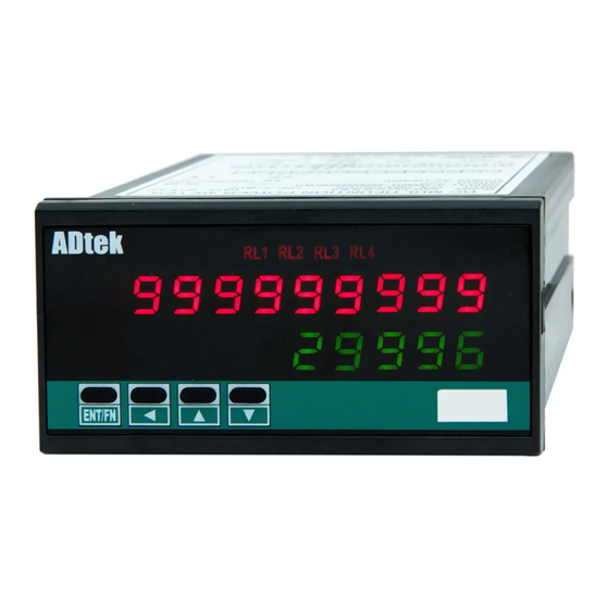
- Page 2 MWH-10-A Operation manual FEATURE Input 1P2W,1P3W,3P3W,3P4W Unbalanced load system's active power, reactive power, apparent power and electric energy (Watts-Hr) etc parameters. Dual display, 10 digits Watts-Hr,lower row 4 2/3 digits Watts. 1 set relay(SPDT) output, having relay function : Hi / Lo / Hi Hold / Lo Hold / OFF; further advance function , start delay, hysteresis, time delay, reset delay etc 1 analogues output same as relay setting parameters.
-
Page 3: Installation
Dimension Installation This meter is installed does not exceed the maximum operating temperature and humidity environment. Front 4 8. 0 9 6. 0 1 00. 0 8 .0 12 .0 ENT/ FIX HOLDER: PANEL CUT-OUT: 104 mm(L) / W M3 +0.2 (W) x 45 +0.2... -
Page 4: Output Wiring
Output wiring Please check if the voltage is correct and connect to the right terminal number when wiring Optional modules: high-precision CT module – YMWH-CT10A – 0.1class 41.0 Connect to Ø13.0(D) Current input of Meter Max Load 50A ... -
Page 5: Analogue Output
Pulse or relay output Due to limitation on number of terminal , pulse and relay output is having same terminal, choose either one Analogue output Open collector:(OPC1) Voltage / Current Output mode: Selectable within parameters setting, voltage or current output need to short J2 &... - Page 6 ■ Operation flow chart: Hold m w h - 1 0 a * * * * * Software Check wiring before power up * * * * * v e r 1 . 0 Model To relay setting 3 p 4 W 1 Self test Wire type LED all on)
- Page 7 A4-20 group aOzo aOtp aOls aOhs 1S back ANALOGUE OUTPUT Analogue Analogue output Analogue output Analogue output GROUP output type and low fine tunning low-scale hi-scale range none 11)00 aOlt zSclr aOsn Analogue Output limit Reset fine tunning output Hi fine tunning Press sec escape to measuring page...
- Page 8 ■ Operating Steps Engineer level Shift Increase Decrease Enter Parameters Display Setting Operation Measurement Display 2 2 ) 0 1 0 ) 0 e n t e r Pass word P c o d e Default 1000 RELAY / PULSE output of the outputs can only choose a functional output EX: Select PULSE output and then RELAY Password correct...
- Page 9 ■ Operating Steps Engineer level Enter Shift Increase Decrease Parameters Display Setting Operation Active power Setting range: Shift Increase Decrease Enter average value 2~99 ※System may have interference or signal unstable setting range avg-p sometimes, causing display unstable: This function help to decrease rapid change on the display.
- Page 10 ■ Operating Steps Engineer level Raely Output Enter Shift Increase Decrease Parameters Display Setting Operation Relay mode Setting type: Shift Enter L O H I L O . H L D H I . H L D Increase Decrease /O F F rl-md &...
- Page 11 ■ Operating Steps Engineer level AO Output Enter Shift Increase Decrease Setting Display Operation Parameters A4-20 Shift Increase Decrease Enter Analogue output Setting range: range Voltage/Current Current: A 0 - 1 0 A 0 - 2 0 : A 4 - 2 0 :0~10 0~20 :4~20...
- Page 12 MWH-10-A MODBUS ADDRESS TABLE**Address number are Hexadecima (User Level) Name Address Range Explain Initial Write/Read Note 0000h total* Energy *(High Word) 0001h 0~9999999999 Energy *(Mid Word) total* 0002h Energy *(Low Word) total* 0008h 3000 rl-sp* -19999~29999 Relay1 Set Point (for watt only) 000Eh aOls* -19999~29999...
- Page 13 MWH-10-A MODBUS ADDRESS TABLE**Address number are Hexadecima (Relay Group) Name Address Range Explain Initial Write/Read Note 0045h 0000~9999 rl-sb Start Band of input for relay energized 0046h rl-sd 0000~5999 Start Delay Time of input 1 for relay energized (0.1second) rl-md 0047h Relay 1 Energized Mode 0: off(no use);...


Need help?
Do you have a question about the MWH-10A and is the answer not in the manual?
Questions and answers