Table of Contents
Advertisement
Quick Links
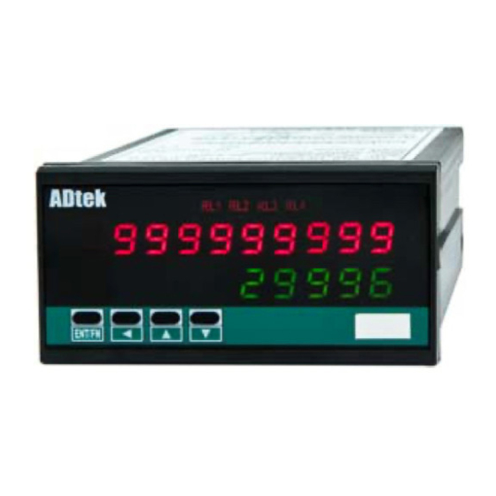
CS2-MC
FEATURE
■
●
Measuring Pulse 0.01Hz~6KHz(A/B phase: 3KHz for each channel);
Contact / NPN / PNP / Voltage Pulse can be switch on rear of meter
●
2 rows LED,display Totalizer 、Batch、Batch count
●
CS2-MC Multifunction Counter design for pulse signal input,
sensors: Proximity switch, Photoelectric sensor, Encoder.... etc.
●
Counter (Increment / Decrement), location-based, batch and
other displays, control, with remote communication
●
4 relays, each can be individual programmed for N/R/C/E/do mode and
timer function.
●
3 external control input for Reset, Gat of totalizer and/or batch
●
Analogue Output and RS485(Modbus RTU mode) available in option
FUNCTIONS
■ Counting
Counting mode :
AB-PHASE:
Up/Down Individual(Individual counting model)
Up/Down Command(Command model)
Multifunction A/B Phase Counter
,
capabilities.
Up Mode
Down Mode
1 / 19
Manual
CS2-MC Manual 2014/9/9
Advertisement
Table of Contents

Related Manuals for ADTEK CS2-MC


Summary of Contents for ADTEK CS2-MC
- Page 1 Contact / NPN / PNP / Voltage Pulse can be switch on rear of meter ● 2 rows LED,display Totalizer 、Batch、Batch count ● CS2-MC Multifunction Counter design for pulse signal input, sensors: Proximity switch, Photoelectric sensor, Encoder..etc. ● Counter (Increment / Decrement), location-based, batch and other displays, control, with remote communication capabilities.
- Page 2 Suspended total / batch Reset of the total / batch to ta l to tal ba tch b atch Le vel Trigger Edge Trigge r By E.C.I. Pa use By E.C.I. Pause or front ke y 2 / 19 CS2-MC Manual 2014/9/9...
-
Page 3: Installation
96.0 100.0 Ter minate Resistor 12.0 (at latest unit): 120~300ohm/ 0.25W (typical: 150ohm ) Dimensions: 96mm x 48mm x 120mm PANEL CUT-OUT Panel Cutout: 93mm x 45mm (advise) +0.2 44.0 Unit: mm +0.2 92.0 3 / 19 CS2-MC Manual 2014/9/9... -
Page 4: Error Massage
E.C.I.: 3 square green LED; : 0.28”(7.2mmH)green digital present values EC1 display when E.C.I. 1 has been closed(dry contact); EC2 display when E.C.I. 1 has been closed(dry contact); EC3 display when E.C.I. 1 has been closed(dry contact); 4 / 19 CS2-MC Manual 2014/9/9... - Page 5 / Batch oFF btCH.n Ab.P-2 nonE GAtE Counter/ total btCH.r Ab.P-4 idV rESEt tL.GtE selection btCH.C Cmd UP tL.rSt bt.GtE bAtCH btCH.E totL.n down bt.rSt bt.Cnt totL.r totL.C totAL NEXT NEXT NEXT NEXT 5 / 19 CS2-MC Manual 2014/9/9...
- Page 6 9(M).59.9(S) 0000~9999 Function Level Lock nonE USEr When the relay operation mode change EnG ALL relay points will reset to zeroPlease re-setting the relay point RS485 GROUP Adres: Device number of the meter 1~255 6 / 19 CS2-MC Manual 2014/9/9...
-
Page 7: User Level
Hi or Lo . Setting Range: rY2.SP: Relay 2 Set-point setting Immediate Value (PV): -199999~999999 Totalizer: -1999999999~9999999999 Shift Down Setting Range: rY3.SP: Relay 3 Set-point setting Immediate Value (PV): -199999~999999 Totalizer: -1999999999~9999999999 Shift Down 7 / 19 CS2-MC Manual 2014/9/9... - Page 8 1 second to back Measuring 畫面 RS485 INPUT RELAY EXTERNAL ANALOGUE GROUP CONTROL OUTPUT GROUP GROUP INPUT GROUP GROUP PRESS PRESS PRESS PRESS PRESS TO ENTER TO ENTER TO ENTER TO ENTER TO ENTER 8 / 19 CS2-MC Manual 2014/9/9...
-
Page 9: Input Group
Setting Range: trG.Md: Trigger Mode AU-bU / AU-bd / Ad-BU / AU-BU: A positive-edge,B Ad-Bd positive-edge trigger AU-Bd: A positive-edge,B & Up&Down Enter negative-edge trigger Ad-BU: A negative-edge,B positive-edge trigger Ad-Bd: A negative-edge,B negative-edge trigger 9 / 19 CS2-MC Manual 2014/9/9... - Page 10 EnG(Engineer Level): Programming level lock. User can get into programming level for checking but setting ALL(All Level): User can get into all level for checking but setting & Up&Down Enter 10 / 19 CS2-MC Manual 2014/9/9...
- Page 11 (N mode is no such function) 0:00.0~9m:59.9s Shift Down rY2.Md:Relay 2 energized mode ….as Relay 1 Energized Mode… Setting Range: oFF / btcH.n / btCH.r / btCH.C / btCH.E / totL.n / totL.r / totL.C / totL.E / do 11 / 19 CS2-MC Manual 2014/9/9...
- Page 12 Batch & Up&Down Enter same as ECI1 ECi.2:External Control Input 2 …other as same as ECI1… nonE / GAtE / rESEt / tL.GtE / tL.rSt / bt.GtE / bt.rSt & Up&Down Enter 12 / 19 CS2-MC Manual 2014/9/9...
- Page 13 Range 0~1000.0;if Ao.LSsetting 200.0,Display 200.0 is output 4mA Setting Range: Ao.HS:Analogue Output relative High Scale Totalizer / Batch Count: -1999999999~9999999999 Batch: -199999~999999 Shift Down ※Ex:Ao.TYP set 4~20mA,Display Range 0~1000.0;if Ao.HSsetting 800.0,Display 800.0 is output 20mA NEXT 13 / 19 CS2-MC Manual 2014/9/9...
- Page 14 Setting Range: 1200 / 2400 / 4800 / 9600 / 19200 & Up&Down Ente Setting Range: PritY:Parity n.Stb.1: None, 1 stop bit n.Stb.2: None, 2 stop bits odd: odd EvEn: Even & Up&Down Ente 14 / 19 CS2-MC Manual 2014/9/9...
-
Page 15: Slave Function
FUNCTION Starting Starting Preset Preset Address Code Address Hi Address Lo DATA Hi DATA Lo ■ CS2-MC ADDRESS TABLE **Address number are Hexadecimal User Level Name Address Range Explain Initial Write/Read Note Three Word Area -1999999999~ 0000h Totalizer (High Word) - Page 16 0=Un-triged 1=Triged SYSTEM 002Ch SYSTEM STATUS STATUS bit0=1, Input EEP fail; bit1=1, N/A; bit2=1, N/A; bit3=1, Analogue Output calibration fail; bit4=1, Analogue Output calibration NG 002Dh 1~9999 Pulse Per Rotation 002Eh Reserved 002Fh Reserved 16 / 19 CS2-MC Manual 2014/9/9...
-
Page 17: Relay Group
4: btCH.E(Batch with E Mode) 5: totL.n(Totalizer with N Mode) 6: totL.r(Totalizer with R Mode) 7: totL.C(Totalizer with C Mode) 8: totL.E(Totalizer with E Mode) 9: Do(Digital Output) 003Dh Relay 2 Energized Time 0000~5999 (0.1second) 17 / 19 CS2-MC Manual 2014/9/9... - Page 18 1: GAtE(Gate for Totalizer & Batch) 2: rESEt(Reset for Totalizer & Batch) 3: tL.GtE(Gate for Totalizer) 4: tL.rSt(Reset for Totalizer) 5: bt.GtE(Gate for Batch) 6: bt.rSt(Reset for Batch) ECI debouncing 0049h 5~255 5~250 16mSec 18 / 19 CS2-MC Manual 2014/9/9...
- Page 19 11000 【RS485 Group】 Name Address Range Explain Initial Write/Read Note 0056h 1~255 RS485 address 0057h RS485 baud rate 0:1200 1:2400 2:4800 3:9600 4:19200 0058h RS485 parity 0: n-8-1 1: n-8-2 2: odd 3: even 19 / 19 CS2-MC Manual 2014/9/9...
Need help?
Do you have a question about the CS2-MC and is the answer not in the manual?
Questions and answers