Table of Contents
Advertisement
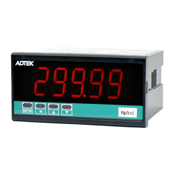
CS1-PR PROCESS Indicator
DESCRIPTION
CS1-PR economic type Process Indicator has been designed
with high accuracy measurement, display and
communication of DC signal 0~10V and 4(0)~20mA.
They are also available 1 option of 1 Relay outputs, 1
Analogue output or 1 RS485(Modbus RTU Mode) interface
with versatile functions such as control, alarm,
re-transmission or communication for a wide range of
industrial applications.
FEATURE
●
Measuring linear signal 0~10V and 0(4)~20mA in one indicator(input code: AV)
●
Square Root function available by programming
●
Option available 1 of 1 relay, 1 analogue output or RS485(Modbus RTU mode)
●
1 relay can be programmed individual to be a Hi / Lo / Hi Latch / Lo Latch energized with Start
Delay / Hysteresis / Energized & De-energized Delay functions.
●
Analogue output or RS 485 communication port in option
●
CE Approved & RoHS
ORDERING INFORMATION
Input
CS1−PR−
Signal
CODE
A1
V1
AV
AO
VO
TECHNICAL SPECIFICATION
Input
Input
Input Range
Impedance
Voltage 0 ~ 10 V
≥ 1M ohm
The Meter can be 0~10V and 0~20mA in one unit, according to connection #11 or #12
Digital calibration by front key
Calibration:
16 bits resolution
A/D converter:
≤± 0.04% of FS ± 1C;
Accuracy:
15 cycles/sec
Sampling rate:
≤100 msec.(when the AvG = "1") in standard
Response Time:
0~10V / 0~5V / 1~5V / 0-10mA / 0~20mA / 4~20mA
Input type:
programmable for coding AV(option)
Display & Functions
Numeric: 5 digits, 0.8"(20.0mm)H red high-brightness LED
LED:
Relay output indication: 1 square red LED
RS 485 communication: 1 square orange LED
E.C.I. function indication: 1 square green LED
Max/Mini Hold indication: 2 square orange LED
Down key function indication(Reset for Max.(Mini.) Hold /
-19999~29999;
Display range:
Lo.SC: Low Scale; Settable range: -19999~+29999
Scaling function:
Hi.SC: High Scale; Settable range: -19999~+29999
Programmable from 0 / 0.0 / 0.00 / 0.000 / 0.0000
Decimal point:
Over range indication: ovFL, when input is over 120% of input range Hi
Under range indication: -ovFL, when input is under -20% of input range Lo
Max / Mini recording: Maximum and Minimum value storage during power on.
PV / Max(Mini) Hold / RS 485 Programmable
Display functions:
Front key functions: Relative PV / PV Hold / Reset for maxi(mini) hold /
Reset for relay energized latch programmable
Settable range: -19999~29999 counts
Low cut:
−
Optional
−
Excitation
−
Output
Supply
OPTION
INPUT RANGE
CODE OPTIONAL O/P
0(4) ~ 20mA / 0 ~ 10mA
None
N
0 ~ 10V / 0(1) ~ 5V
1 Relay
R1
0~10V/0(4)~20mA(all in one)
0(1) ~ 5 V
V
0 ~ 10 V
Specify A input
Specify V input
0 ~ 10 mA
I
0(4)~20 mA
RS 485
8
Relay, Analogue Output
or RS485 Port can be
selected one only.
Input
Input Range
Impedance
Current 4(0)~20 mA
250 ohm
PV Hold / Rel. PV): 1 square green LED
Excitation Supply DC24V in build for 2 wire transmitters
Aux.
Powered
CODE EXCIT. SUPPLY
None
N
DC 24V
E24
Specify
EO
Digital fine adjust:
Average:
Moving average:
Digital filter:
Set-points:
Control relay:
Relay energized mode: Energized levels compare with set-points:
Energizing functions: Start delay / Energized & De-energized delay / Hysteresis
Accuracy:
Ripple:
Response time:
Isolation:
Output range:
Output capability:
Functions:
Digital fine adjust:
CODE
AXU. POWER
AC115/230V
A
OPTION 4
AC/DC 85~264V
* It means RoHS
ADH*
version.
AC/DC 20~90V
ADL*
* ADH* will be available
at Jan. 2008
Pv.Zro: Settable range: -19999~+29999
Pv.SPn: Settable range: -19999~+29999
Settable range: 1~99 times
Settable range: 1(None)~10 times
Settable range: 0(None)/1~99 times
One set-point
1 Relay, FORM-C, 5A/230Vac, 10A/115V
Hi / Lo / Hi.HLd / Lo.HLd programmable
Energized Latch
Start band(Minimum level for Energizing): 0~9999counts
Start delay time: 0:00.0~9(Minutes):59.9(Second)
Energized delay time: 0.00.0~9(Minutes):59.9(Second)
De-energized delay time: 0.00.0~9(Minutes):59.9(Second)
Hysteresis: 0~5000 counts
±
≤
0.1% of F.S.;
≤± 0.1% of F.S.
≤100 msec. (10~90% of input)
AC 2.0 KV between input and output
Specify either Voltage or Current output in ordering
Voltage: 0~5V / 0~10V / 1~5V programmable
Current: 0~10mA / 0~20mA / 4~20mA programmable
Voltage: 0~10V: ≥ 1000Ω;
Current: 4(0)~20mA: ≤ 600Ω max
Ao.HS(output range high): Settable range: -19999~29999
Ao.LS(output range Low): Settable range: -19999~29999
Ao.Zro: Settable range: -38011~+27524
Ao.SPn: Settable range: -38011~+27524
C1-01-1/7-2007-11-07
Advertisement
Table of Contents

Related Manuals for ADTEK CS1-PR


Summary of Contents for ADTEK CS1-PR
- Page 1 CS1-PR PROCESS Indicator DESCRIPTION CS1-PR economic type Process Indicator has been designed with high accuracy measurement, display and communication of DC signal 0~10V and 4(0)~20mA. They are also available 1 option of 1 Relay outputs, 1 Analogue output or 1 RS485(Modbus RTU Mode) interface...
- Page 2 RS 485 Communication(option) INSTALLATION Modbus RTU mode Protocol: 1200/2400/4800/9600/19200/38400 programmable Baud rate: The meter should be installed in a location that dose not exceed the 8 bits Data bits: maximum operating temperature and provides good air circulation. Even, odd or none (with 1 or 2 stop bit) programmable Parity: 1 ~ 255 programmable Address:...
- Page 3 Display & Functions Digital fine adjustment: Max / Mini recording: The meter will storage the maximum and minimum value in Users can get Fine Adjustment for Zero & Span of PV by front key of 【User Level】during power on in order to review drifting the meter, and “Just Key In”...
- Page 4 Energized functions: Start delay / Energized & De-energized delay / Hysteresis RS 485 Communication(option) The RS485’s protocol is Modbus RTU mode, and baud rate up to Start Delay Energized / De-energized 38400 bps. It’s convenience to remote monitoring, display for Delay &...
- Page 5 FRONT PANEL: Operating Key: 4 keys for Enter(Function) / Max. Hold status Relay status Shift(Escape) / Up key / Down key Indication Comm. status R L 1 CO M CI11 Front Key Setting Status Function Index function status Increase number Go back to previous Up key Display screen...
- Page 6 OPERATING DIAGRAM (The detail description of operation, please refer to operating manual.) Power ON User Level Self-diagnosis Press for 1 sec. can back to Measuring Show the This page will Min:PV model number model number show out, Minimum firmware when dSPLY storage version set to be...
- Page 7 Z.S.CLr: Clear Fine Zero & Span Adjustment for PV display nonE Pv.Zro Pv.SPn botH dSPLY: Display Function Pv Mini.H MAx.H RS485 Lo.Cut: Low Cut Function -19999~+29999 AvG: Average update for PV 1(None)~ 99 times M.AvG: Moving Average update for PV 1(None)~ 10 times d.FiLt: Digital...
Need help?
Do you have a question about the CS1-PR and is the answer not in the manual?
Questions and answers