Table of Contents
Advertisement
Quick Links
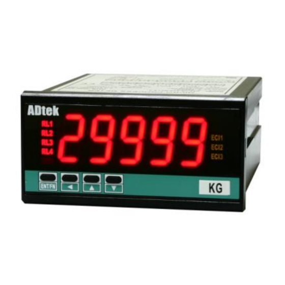
CS2-SG STRAIN GAUGE Indicator
DESCRIPTION
CS2-SG Strain Gauge Indicator has been designed with high accuracy
measurement, display and communication of DC signal 0~1.0/~4.0mV
or 0~10.0/~40.0mV as like as Load Cell or Strain Gauge.
The meter supports Field Calibration function. It can be calibrated
with sensor(Load Cell/Strain Gauge) to meet machinery structure.
They are also building in 4 Relay outputs, 3 External Control Inputs, 1
Analogue output and 1 RS485(Modbus RTU Mode) interface with
versatile functions such as control, alarm, re-transmission and
communication for a wide range of machinery and testing equipments
applications.
FEATURE
●
Measuring load cell, strain gauge signal 0~1.0/~2.0/~4.0/~10.0/~20.0/~40.0mV/V(Specify)
●
Field calibration with load cell or strain gauge to meet the system requirement
●
4 relay can be programmed individual to be a Hi / Lo / Hi Latch / Lo Latch / Go energized with Start Delay /
Hysteresis / Energized & De-energized Delay functions, or to be a remote control.
●
Analogue output and RS 485 communication port in option
●
3 external control inputs can be programmed individual to be Tare (Relative PV) / PV Hold / Maximum or
Minimum Hold / DI (remote monitoring) / Reset for Relay Energized Latch....
●
CE Approved & RoHS
APPLICATIONS
●
Testing Equipments for weight/force Measuring, Alarm, Control and Communication with PC/PLC
●
Leakage testing equipment by tare and relay function.
●
Weighting control for packing machine, filling machine.
ORDERING INFORMATION
CS2−SG−
Input
Signal
COD
I/P RANGE CODE I/P RANGE
E
1.0mV/V
S1
2.0mV/V
S2
4.0mV/V
S3
Specify
SO
TECHNICAL SPECIFICATION
Input
Measuring Range
Input Impedance
0~1.0/~2.0/~4.0 mV/V
≥ 1M ohm
0~10.0/~20.0/~40.0 mV/V
Digital calibration by front key
Calibration:
Calibration with sensor input high & low to meet system
Field calibration:
structure. And field calibration reset is not change the
accuracy & linear of factory calibration.
16 bits resolution
A/D converter:
≤± 0.04% of FS 1C;
Accuracy:
15 cycles/sec
Sampling rate:
High speed mode: can be 60cycle/sec(scaling:0~6000)
≤100 m-sec.(when the AvG = "1") in standard
Response time:
Input High and Low programmable
Input range:
aIhi: Settable range: 0.00~100.00% of input range
aIlo: Settable range: 0.00~100.00% of input range
Display & Functions
Numeric: 5 digits, 0.8"(20.0mm)H red high-brightness LED
LED:
Relay output indication: 4 square red LED
RS 485 communication: 1 square orange LED
E.C.I. function indication: 3 square green LED
Max/Mini Hold indication: 2 square orange LED
-19999~29999; 5 Digital Display:-19999~99999
Display range:
lOsc: Low Scale; Settable range: -19999~+29999/99999
Scaling function:
hIsc: High Scale; Settable range: -19999~+29999/99999
Programmable from 0 / 0.0 / 0.00 / 0.000 / 0.0000
Decimal point:
C2-03
-2/11
−
−
−
Relay
Analogue
Output
Output
OPTION 1
OPTION 2
OPTION 3
CODE RELAY O/P
None
10.0mV/V
S8
N
20.0mV/V
2 Relay
S9
R2
40.0mV/V
4 Relay
SA
R4
Excitation Voltage
DC 5V, 40mA
or DC 10V, 40mA
CS2-SG-2010-09-27
−
−
RS 485
Excitation
Aux.
Port
Supply
Powered
CODE
ANALOG
CODE RS485 PORT
O/P
None
None
N
N
RS 485
0(1) ~ 5 V
8
V
0 ~ 10 V
0 ~ 10 mA
I
4(0)~20 mA
Over range indication: ovfl, when input is over
Under range indication: -ovfl, when input is under
Max / Mini recording: Maximum and Minimum value storage during power on.
Display functions:
Front key functions:
Low cut:
Digital fine adjust:
Reading Stable Function
Average:
Moving average:
Digital filter:
Control Functions(option)
Set-points:
Control relay:
Relay energized mode:
Energizing functions:
−
*Optional
Customize function is welcome. Please
Function
contact with our sales for detail.
CODE EXCITATION
CODE AXU. POWER
DC 5V
AC 115/230V
A
E05
DC 10V
E10
OPTION 4
Specify
AC 85~264V
EO
ADH
DC 100~300V
CODE OPTION FUNC.
DC 20~56V
High Speed
ADL
HSM
Mode
5DG
5 Digital Display
20%
of input range Hi
-20%
of input range Lo
PV / Max(Mini) Hold / RS 485 Programmable
Up and down key can be set to be a function as ECI.
Settable range: -19999~29999 counts
pVzro: Settable range: -19999~+29999/99999
pVspn: Settable range: -19999~+29999/99999
Settable range: 1~99 times
Settable range: 1(None)~10 times
Settable range: 0(None)/1~99 times
Four set-points
Four relays
Relay 2 & Relay 3: Dual FORM-C, 5A/230Vac, 10A/115V
Relay 1 & Relay 4: Dual FORM-A, 1A/230Vac, 3A/115V
Energized levels compare with set-points:
Hi / Lo / Go.12 / Go.23 / Hi.HLd / Lo.HLd; programmable
DO function: Energized by RS485 command of master.
Start delay / Energized & De-energized delay / Hysteresis /
Energized Latch
Start band(Minimum level for Energizing): 0~9999counts
Start delay time: 0:00.0~9(Minutes):59.9(Second)
Energized delay time: 0.00.0~9(Minutes):59.9(Second)
De-energized delay time: 0.00.0~9(Minutes):59.9(Second)
Hysteresis: 0~5000 counts
Advertisement
Table of Contents

Related Manuals for ADTEK CS2-SG


Summary of Contents for ADTEK CS2-SG
- Page 1 CS2-SG STRAIN GAUGE Indicator DESCRIPTION CS2-SG Strain Gauge Indicator has been designed with high accuracy measurement, display and communication of DC signal 0~1.0/~4.0mV or 0~10.0/~40.0mV as like as Load Cell or Strain Gauge. The meter supports Field Calibration function. It can be calibrated with sensor(Load Cell/Strain Gauge) to meet machinery structure.
-
Page 2: Installation
Load Cell FRONT PANEL Output Output RS485 Port E.S. Max. Hold status Relay status Indication Comm. status R L1 C O M CI11 Control Input status Display screen Mini. Hold status ENT/FN Operation Key Engineer Unit CS2-SG-2010-09-27 C2-03 -3/11... -
Page 3: Function Description
In past, The meter normally receive 4~20mA or 0~10V from AO or digital output from BCD module of PLC. We support a new solution that PV shows the value from RS485 command of master can so that can be save cost and wiring from PLC. C2-03 CS2-SG-2010-09-27 -4/11... - Page 4 The function is to avoid the miss action caused by noise. Sometime, the [ry@sp] (Hi) > PV > [ry#sp] (Lo) display value will swing caused by spark of contactor…etc.. User can set a period to delay the relay energized. CS2-SG-2010-09-27 C2-03 -5/11...
- Page 5 Span adjust [aOspn]: Fine Span Adjustment for Analog Output; rYrst(Reset the Relay energized latch). When the PV Settable range: -38011~27524; meets the condition of relay energizing, the relay will be energized and latch until the ECI is to be closed. C2-03 CS2-SG-2010-09-27 -6/11...
- Page 6 Load (Supervisor Control And Data Acquisition) system. The baud rate can be Cell measuring. Now, our CS2-SG support easier process to do it called “Field Calibration”. up to 38400 bps. It's not only can be read the measured value and DI...
-
Page 7: Front Panel
ECI2 close. M.RS(Maximum or Minimum Reset) / If the front key function has been set, the terminal input for ECI R.RS(Reset for Relay Latch) will be disabling. ● Engineer Label: over 80 types. C2-03 CS2-SG-2010-09-27 -8/11... -
Page 8: Operating Diagram
Span Clear for point to be Down Key pVzro ry!fd E2=dn ZSclr Adjustment for delay time Adjustment function PV display yes / none / aOzro / 0.00.0~ -19999~29999 aOspn / both 9(M).59.9(S) /99999 Next Page Next Page Next Page CS2-SG-2010-09-27 C2-03 -9/11... - Page 9 / go-@3 ry$hy: Relay 4 Hysteresis ry$hy 0~5000 counts ry$rd: Relay 4 )0)0 energized delay ry$rd time 0.00.0~ 9(M).59.9(S) ry$fd: Relay 4 )0)0 de-energized ry$fd delay time 0.00.0~ 9(M).59.9(S) Plesae refer to operating manual for detail description C2-03 CS2-SG-2010-09-27 -10/11...
-
Page 10: Field Calibration
Higher scale Csel: Calibration parameter selection Csel Press to access the function and stand by deflt selection Press to select (default: defld); Settable: defld / field defld (default calibration) field (Field calibration) CS2-SG-2010-09-27 C2-03 -11/11...
Need help?
Do you have a question about the CS2-SG and is the answer not in the manual?
Questions and answers