Advertisement
Quick Links
Advertisement

Related Manuals for ADTEK CPM-10


Summary of Contents for ADTEK CPM-10
- Page 1 CPM-10 Economical Multifunction Power Meter Operation manual Rev1.2 2017-04...
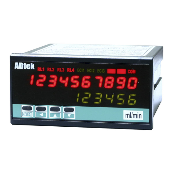
- Page 2 Motor control/ panel power monitoring/power consumption monitor and control/power distribution system /intelligent building & automation power management system/ power testing equipment The CPM-10 system (SCADA) monitoring as a power front-end measurement unit, for volume measurement and control of remote power. Industry-standard RS-485 communication interface and MODBUS protocol, making connecting to the network easily convenient, want to choose the management of the SCADA system.。...
- Page 3 Dimension Installation This meter is installed does not exceed the maximum operating temperature and humidity environment. Front 48.0 96.0 100.0 12.0 EN T/ F IX HOLDER: PANEL CUT-OUT: 1 04 mm(L ) / W M3 +0.2 +0. 2 (W) x 44 (H) mm 1 .0 ~8.0 mm Cut size...
- Page 4 Relay output to terminal Relay output Clamp CT Optional of Clamp CT, make sure (1)CT of the SN number with the CPM-10 SN number, as shown (2)On the label A:A-Phase; B:B-Phase ; C:C-Phase ; According to the phase matching (3)S1 (white) connected” K” side;...
- Page 5 Analogue output Wire terminal Analogue output Terminal: A1~A16: 20A/600Vac, M3.5, 22~12AWG; Voltage / Current Max Torque: 13Kg-cm Output mode: Selectable 7.0mm max within parameters setting, voltage or current output need to short J2 & J3 on output PCB 7.0mm max module.
- Page 6 ! 3 rYrst Relay 1.2 setting point Relay 1.1 setting point Relay 1.3 setting point Reset relay cpm-10 Version Model Hold escape to measuring page Parameter setting(A-1),connection different.will have a different display(tick shown) 2 2 ) 0 1 0 ) 0...
-
Page 7: Parameter Description
Engineer level 2 2 ) 0 1 0 ) 0 PV value rs485 pulse input relay e n t e r group group group group P.code group Correct P c o d e PULSE RELAY INPUT RS485 ANALOGUE Password GROUP GROUP GROUP GROUP... - Page 8 Engineer level PV value 2 2 ) 0 1 0 ) 0 rs485 pulse input relay e n t e r group group group group P.code group Correct P c o d e PULSE RELAY INPUT ANALOGUE RS485 Password GROUP GROUP GROUP GROUP...
- Page 9 Engineer level Parameter Description Explain Index Lo(Low Level Energized): Relay mode LO/HI/LO.HLD/ When the displayed value is lower than the set value HI.HLD/OFF (PV <Set point), the relay action。 Hi(High Level Energized): When the displayed value is higher than the set value (PV>...
- Page 10 Parameter Description Index Explain AO corresponding the parameters: AO corresponding the parameters: p f - a : v a v g Phase A power factor 3 Phase average voltage p f - b : i a v g Phase B power factor 3 Phase apparent power p f - c : f r e q :...
- Page 11 Engineer level PV value 2 2 ) 0 1 0 ) 0 rs485 pulse input relay e n t e r group group group P.code group group Correct P c o d e PULSE RELAY INPUT RS485 ANALOGUE Password GROUP GROUP GROUP GROUP...
-
Page 12: User Level
Version v e r ! 3 There is no relay View only Model functions cpm-10 Will only display P re s s se c e sc ap e to b eg i ni n g p ag e. version Press sec escape to measuring page. - Page 13 Operating Steps ■ User Level Operation Parameters Setting Display No need to set Power on Self test Check the wiring LED all on * * * * * * * * * * Press 1Sec Wiring Model 3 p 4 w c p m - 1 0 Into the v e r 1 .
-
Page 14: Operating Steps
Operating Steps ■ User Level Operation Parameters Setting Display Each phase voltage refers to the relative N and 38)5 B Phase 1-11 View only white voltage。 Va(Vb、Vc)with Vn voltage voltage。3P4W wiring, only to show the line voltage of N, if you want to understand the line to line voltage, is only the value multiplied by 1.732.。... - Page 15 Operating Steps ■ User Level Operation Parameters Setting Display 1000 1-23 View only B Phase Reading needs with the unit M、K or None(var)。 reactive power C Phase 1000 1-24 View only reactive power A Phase View only 1000 1-25 apparent power Reading needs with the unit M、K or None(var)。...
- Page 16 Operating Steps ■ Engineer level Shift Increase Decrease Enter Parameters Display Setting Operation Measurement Display 2 2 ) 0 1 0 ) 0 Pass word e n t e r P c o d e Default 1000 RELAY / PULSE output of the outputs can only choose a functional output EX: Select PULSE output and then RELAY Password correct...
- Page 17 Operating Steps ■ Engineer level Enter Shift Increase Decrease Parameters Display Setting Operation Active power Setting range:2~99 Shift Increase Decrease Enter average value ※System may have interference or signal unstable setting range: avg-p sometimes, causing display unstable: This function help to decrease rapid change on the display.
- Page 18 Operating Steps ■ Engineer level Raely Output Enter Shift Increase Decrease Parameters Display Setting Operation Setting type: Relay R1.1 Shift Increase Decrease Enter L O H I L O . H L D H I . H L D O F F r!!md &...
- Page 19 Operating Steps ■ Engineer level Raely Output Enter Shift Increase Decrease Display Setting Operation Parameters B-11 Relay R stard Setting range:00.00~99.99 Shift Increase Decrease Enter band: r!!sb When display exceed set start band and after Start delay time then relay compare PV value, energized. )0)0 B-12 Relay R...
- Page 20 Operating Steps ■ Engineer level Raely Output Enter Shift Increase Decrease Display Setting Operation Parameters B-23 Relay R1.3 Setting range:0.00~50.00 & Press values blink press change value or selection hysteresis time: when done press to next setting or hold r!#hy to previous selection list B-24 Relay R 3 start...
- Page 21 Operating Steps ■ Engineer level Enter AO Output Shift Increase Decrease Setting Display Operation Parameters A/O Low scale Setting range: Shift Increase Decrease Enter range: -199.99~299.99 aOls A 4 - 2 0 Ex When A O set (4~20mA) display value as a O l s 0~199.99 user may set...
- Page 22 Operating Steps ■ Engineer level Enter Pulse Output Shift Increase Decrease Setting Display Operation Parameters PULSE pulse PULSE Press p u l s e g r o u p 1 sec to [ GROUP GROUP group Display P 1s Back Pulse output Setting range:1 9999 Shift...
- Page 23 CPM-10 MODBUS ADDRESS TABLE**Address number are Hexadecima Modbus Initial Read/White Name Address Range Explain Address Active Energy (High word) 40001 0000h 0~9999999999 Active Energy (Mid word) 40002 0001h aEtl Active Energy (low word) 40003 0002h Re-Active Energy (High word) 40004...
- Page 24 CPM-10 MODBUS ADDRESS TABLE**Address number are Hexadecima Modbus Range Explain Name Address Initial Read/White Address The parameter relative to Relay 1.1 0: Average Voltage 1: Average Current 2: Frequency 3: Total Active Power 4: Total Re-active Power 5: Total Apparent Power 6: Average Power Factor...
- Page 25 CPM-10 MODBUS ADDRESS TABLE**Address number are Hexadecima Modbus Range Explain Name Address Initial Read/White Address The parameter relative to Analog Output 1 0: Average Voltage 1: Average Current 2: Frequency 3: Total Active Power 4: Total Re-active Power 5: Total Apparent Power 6: Average Power Factor...
Need help?
Do you have a question about the CPM-10 and is the answer not in the manual?
Questions and answers