
Subscribe to Our Youtube Channel
Related Manuals for Siemens 6GA7202-2AA10-1BF1


Summary of Contents for Siemens 6GA7202-2AA10-1BF1
- Page 1 Operating Instructions Cranes SIMOCRANE CenSOR Camera measuring system Issue 07/2021 www.siemens.com/simocrane...
- Page 3 Maintenance and service Technical data Dimension drawings Components of the product/ spares/accessories Appendix Valid for the device with the following order number: List of abbreviations and Camera 6GA7202-2AA10-1BF1 acronyms Camera 6GA7202-2AA22-0BA1 Valid for software version Glossary SIMOCRANE CenSOR V3.0 07/2021 A5E49956741B AB...
- Page 4 Note the following: WARNING Siemens products may only be used for the applications described in the catalog and in the relevant technical documentation. If products and components from other manufacturers are used, these must be recommended or approved by Siemens. Proper transport, storage, installation, assembly, commissioning, operation and maintenance are required to ensure that the products operate safely and without any problems.
-
Page 5: Table Of Contents
Table of contents Introduction ............................7 Basic safety instructions ........................9 General safety instructions relating to hardware ..............9 General safety instructions relating to software ..............10 2.2.1 Malfunctions of the machine as a result of incorrect or changed parameter settings.... 10 Recycling and disposal ...................... - Page 6 Table of contents Connecting the camera ...................... 49 Setting up the camera......................55 Parameterization ..........................61 Start page.......................... 66 Application ........................67 8.2.1 Program ..........................67 8.2.2 Image and result views ...................... 71 8.2.3 Image acquisition ......................75 8.2.3.1 Image ..........................76 8.2.3.2 Trigger..........................
- Page 7 Table of contents Technical data............................ 133 11.1 SIMATIC MV540 H CRANES camera ................... 133 11.1.1 Technical specifications of SIMATIC MV540 H CRANES............133 11.1.2 Mechanical ambient conditions..................134 11.1.3 Climatic ambient conditions..................... 136 11.1.4 Transportation and storage ....................136 11.1.5 Electromagnetic compatibility ..................
- Page 8 Table of contents SIMOCRANE CenSOR Operating Instructions, 07/2021...
-
Page 9: Introduction
Introduction Contents of this document The operating instructions contain a description of the SIMOCRANE CenSOR camera measuring system. SIMOCRANE CenSOR is used in combination with SIMOCRANE SC Integrated or SIMOCRANE CeSAR standalone to eliminate the effects of load sway on: •... - Page 10 Introduction SIMOCRANE CenSOR Operating Instructions, 07/2021...
-
Page 11: Basic Safety Instructions
Basic safety instructions General safety instructions relating to hardware The camera measuring system is operated in the vicinity of electrical installations. This area may contain high voltages, moving machine parts, hydraulic and pneumatic systems. Consequently, follow the following general safety instructions. WARNING Electric shock and danger to life due to other energy sources Touching live components can result in death or severe injury. -
Page 12: General Safety Instructions Relating To Software
Basic safety instructions 2.2 General safety instructions relating to software WARNING Electric shock due to equipment damage Improper handling may cause damage to equipment. For damaged devices, hazardous voltages can be present at the enclosure or at exposed components; if touched, this can result in death or severe injury. -
Page 13: Recycling And Disposal
Basic safety instructions 2.3 Recycling and disposal WARNING Malfunction due to uncontrolled changeover between operating states Uncontrolled change of the operating state can cause malfunctions on machines that can result in injuries or death. • Assess the effects of changeover between operating states in the risk analysis. •... -
Page 14: Industrial Security
Industrial security (http://www.siemens.com/industrialsecurity) Siemens products and solutions undergo continuous development to make them increasingly more secure. Siemens strongly recommends that product updates are applied as soon as they are available and that the latest product versions are used. Using outdated or unsupported versions can increase the risk of cyber threats. -
Page 15: Additional Specific "Security Measures
See also safety instruction Industrial security (http://www.siemens.com/ industrialsecurity). In order to protect plants, systems, machines and networks against cyber attack, Siemens industrial security functions can be incorporated into a customized industrial security concept. You can find more information about the industrial security functions of SIMATIC/SIMOTION/ SINAMICS under: •... - Page 16 Basic safety instructions 2.5 Additional specific "security measures" SIMOCRANE CenSOR Operating Instructions, 07/2021...
-
Page 17: Safety Instructions For Simocrane Censor
The device is only permitted for use in the applications described in the catalog and in the technical description. The device is only permitted for use in conjunction with third-party devices and components recommended or approved by Siemens. This product can only function reliably and safely if the following conditions are fulfilled: •... - Page 18 Safety instructions for SIMOCRANE CenSOR System expansions Install only system expansions that are intended for this device. Installing other expansions can damage the system or violate the safety provisions and regulations for radio interference suppression. You can obtain information on system expansions suitable for installation from the technical customer service or from the sales office responsible for your area.
- Page 19 Safety instructions for SIMOCRANE CenSOR Connecting the 24 V DC power supply CAUTION Connection to the 24 V DC power supply The device should only be connected to a 24 V DC power supply that satisfies the requirements of safe extra low voltage (SELV). An NEC class 2 power source is required in order to comply with UL requirements (according to UL 60950-1).
- Page 20 Safety instructions for SIMOCRANE CenSOR WARNING Risk of falling SIMOCRANE CenSOR components All screwed joints are equipped with suitable screw locks to safely prevent SIMOCRANE CenSOR components from falling down after installation. • Use only these screw locks for installation. •...
-
Page 21: System Description
System description Overview The SIMOCRANE CenSOR camera measuring system continuously detects the position, the skew and the velocities of a reflector (with an additional reflector as an option). SIMOCRANE CenSOR is primarily used in conjunction with: • SIMOCRANE SC Integrated - or - •... - Page 22 System description 4.1 Overview Web Based Management (WBM) • Completely installation-free • User-friendly HTML5 design • Short response times • Secure communication over https • Login and user management • Versatile HTML pages for monitoring the camera • Extensive operator control and monitoring functions even in processing mode •...
- Page 23 System description 4.1 Overview Figure 4-2 SIMATIC MV540 H CRANES camera installation drawing SIMOCRANE CenSOR Operating Instructions, 07/2021...
-
Page 24: Design Of Simatic Mv540 H Cranes
System description 4.2 Design of SIMATIC MV540 H CRANES Design of SIMATIC MV540 H CRANES The following figure shows an example of the design of the SIMATIC MV540 H CRANES camera. ① LED display ② Protective lens barrel ③ Nameplate ④... -
Page 25: Versions
System description 4.3 Versions Versions 2 versions are available: Version 1 (indoor) Version 2 (outdoor) Indoor product type Outdoor product type • SIMATIC MV540 H CRANES camera • SIMATIC MV540 H CRANES camera • C-mount lenses • C-mount lenses • Protective lens barrel •... -
Page 26: Product Features Of The Simatic Mv540 H Cranes Camera
System description 4.4 Product features of the SIMATIC MV540 H CRANES camera Product features of the SIMATIC MV540 H CRANES camera SIMATIC MV540 H CRANES camera • Ethernet 10/100/1000 Mbit/s for UDP and PROFINET IO • Resolution 1280 x 1024 pixels •... -
Page 27: Functions
System description 4.5 Functions Functions Method of operation Figure 4-4 Measured value acquisition The camera measuring system determines: • The vertical offset to the camera axis in millimeters • The distance between camera and reflector • The skew around the camera axis Reflector skew is measured in 1/100 degrees. - Page 28 System description 4.5 Functions The accuracy of deflection for the x and y axes can be up to ± 4 mm at 75 m. This accuracy depends on the reflector size and on the distance between the camera and the reflector.
-
Page 29: Components
System description 4.6 Components Components 4.6.1 SIMATIC MV540 H CRANES camera The SIMATIC MV540 H CRANES camera represents the core of the SIMOCRANE CenSOR measuring system. Depending on the version, the camera is supplied either: • Fully assembled in a stainless steel housing with IR flash (outdoor) - or - •... -
Page 30: Ir Flash
System description 4.6 Components 4.6.3 IR flash A flash is provided to improve detection performance. Shorter exposure times can be achieved, making faster sampling rates possible. The flash can improve the response times of the control on interference if SIMOCRANE CenSOR is used in conjunction with: •... -
Page 31: Reflector
System description 4.6 Components 4.6.4 Reflector WARNING Risk of electric shock The retroreflective reflectors for the outdoor crane are equipped with a 230 V AC foil heater. The heater is attached inside the housing. During operation, a dangerous voltage is present in the heater. A damaged heating foil can result in severe injury or death. -
Page 32: Housing (Only Outdoor Version)
System description 4.6 Components The retroreflective foil acts like a "cat's eye" and is illuminated by an infrared LED flash fitted directly beside the SIMATIC MV540 H CRANES camera. • The light of the flash is reflected in the SIMATIC MV540 H CRANES camera. •... -
Page 33: Commissioning And Diagnostics
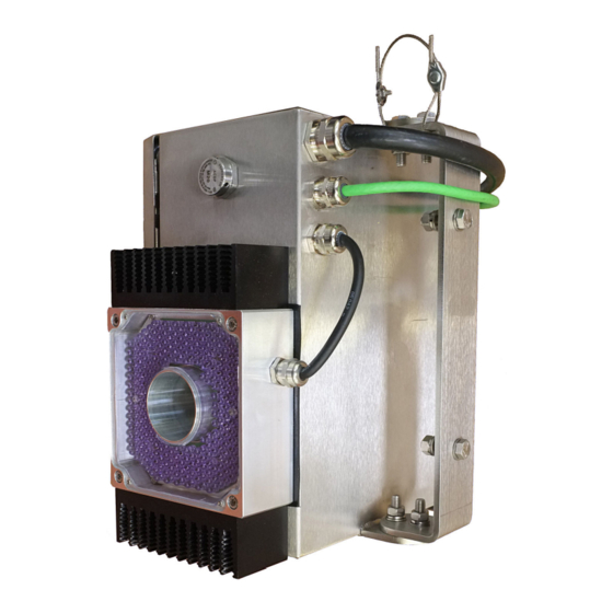
System description 4.7 Commissioning and diagnostics • The SIMATIC MV540 H CRANES camera is supplied in a V4A stainless steel housing. • The integrated heater prevents frost damage and fogging of the protective screen. Figure 4-6 Open housing Commissioning and diagnostics User interface The user interface is based on web server technology. - Page 34 System description 4.7 Commissioning and diagnostics Diagnostic functions The SIMATIC MV540 H CRANES camera offers extensive diagnostic functions. These diagnostic functions make it possible to identify causes of errors based on the recorded images in the event of an unsuccessful reflector search. SIMOCRANE CenSOR Operating Instructions, 07/2021...
-
Page 35: Area Of Application
Area of application SIMOCRANE CenSOR operating conditions The SIMATIC MV540 H CRANES camera is designed for fixed installation in weather-protected locations. The camera fulfills the operating conditions according to: • DIN IEC 60721-3-3 class 3M3 (mechanical requirements) • DIN IEC 60721-3-3 class 3K3 (climatic ambient conditions) Operating conditions of version 1 (indoor) The components of the SIMATIC MV540 H CRANES camera include: •... - Page 36 Area of application The stainless steel housing of the heatable, retroreflective reflectors has no degree of protection. The internal electrical components (heating elements and switch box) are protected against environmental influences according to DIN EN 60529. This means that resistance to the following ambient conditions is guaranteed: •...
-
Page 37: Installation/Connection
Installation/connection Unpacking, installing and connecting Two options are available for connecting the SIMATIC MV540 H CRANES camera to a controller: 1. PROFINET interface To connect the Ethernet interface of the SIMATIC 540 H CRANES camera to the PROFINET interface of the SIMOTION module, proceed as described in these Operating Instructions: See the chapter Connection via PROFINET IO (Page 120). -
Page 38: Simocrane Censor For An Indoor Crane
Installation/connection 6.2 SIMOCRANE CenSOR for an indoor crane SIMOCRANE CenSOR for an indoor crane 6.2.1 Installing the SIMATIC MV540 H CRANES camera and reflector on the indoor crane Install the camera on the trolley of the indoor crane Figure 6-1 SIMATIC MV540 H CRANES camera installation drawing WARNING No persons in the area below the crane trolley... - Page 39 Installation/connection 6.2 SIMOCRANE CenSOR for an indoor crane WARNING Risk of falling SIMOCRANE CenSOR components All screwed joints are equipped with suitable screw locks to safely prevent SIMOCRANE CenSOR components from falling down after installation. • Always use these screw locks for installation. •...
- Page 40 Installation/connection 6.2 SIMOCRANE CenSOR for an indoor crane Figure 6-2 SIMATIC MV540 H CRANES with attached lighting unit and mounting plate Install the reflector on the load suspension device of the indoor crane NOTICE Install the reflector properly Improper installation will damage the reflector. Note The reflector must be easily visible from above / maximum skew of the reflector •...
-
Page 41: Connect Components On The Indoor Crane
Installation/connection 6.2 SIMOCRANE CenSOR for an indoor crane • Install the reflector on the load suspension device as shown in the "reflector installation drawing". ≤ Figure 6-3 Reflector installation drawing • Bolt the reflector to the mounting points provided on the load suspension device using the M8 bolts. - Page 42 Installation/connection 6.2 SIMOCRANE CenSOR for an indoor crane Camera and flash • Connect the following cables that are included in the scope of delivery: – RJ45 Ethernet – Power-IO-RS232 cable, open cable end – Lamp cable, open cable end • Connect the camera and flash unit as illustrated in the figure below: ①...
- Page 43 Installation/connection 6.2 SIMOCRANE CenSOR for an indoor crane The following table lists the pin assignment of the cable: Table 6-1 Pin assignment of the cable Power L1 / phase 230 V AC N neutral Ground PE Diagnostics PC (during commissioning) Connect the diagnostics PC to the computer unit via an Ethernet cable, either directly or via a switch.
-
Page 44: Simocrane Censor For An Outdoor Crane
Installation/connection 6.3 SIMOCRANE CenSOR for an outdoor crane SIMOCRANE CenSOR for an outdoor crane 6.3.1 Installing the camera housing and reflector on the outdoor crane Install the camera housing on the trolley of the outdoor crane Figure 6-5 Camera housing installation drawing WARNING Risk of injury / No persons in the area below the crane trolley Persons are not permitted to stand in the area below the crane trolley when the SIMATIC MV540... - Page 45 Installation/connection 6.3 SIMOCRANE CenSOR for an outdoor crane WARNING Risk of falling SIMOCRANE CenSOR components All screwed joints are equipped with suitable screw locks to safely prevent SIMOCRANE CenSOR components from falling down after installation. • Always use these screw locks for installation. •...
- Page 46 Installation/connection 6.3 SIMOCRANE CenSOR for an outdoor crane Install the reflector on the load suspension device of the outdoor crane NOTICE Install the reflector properly Improper installation will damage the reflector. Note The reflector must be easily visible from above / maximum skew of the reflector •...
-
Page 47: Connect Components On The Outdoor Crane
Installation/connection 6.3 SIMOCRANE CenSOR for an outdoor crane 6.3.2 Connect components on the outdoor crane Note Use a regulated switched-mode power supply Use a regulated switched-mode power supply: 24 V/at least 10 A, surge-proof. Next, connect the SIMOCRANE CenSOR components. Heaters The heaters of the camera housing and the reflector are self-regulating. - Page 48 Installation/connection 6.3 SIMOCRANE CenSOR for an outdoor crane Reflector WARNING Risk of electric shock The retroreflective reflectors for the outdoor crane are equipped with a 230 V AC foil heater. The heater is attached inside the housing. During operation, a dangerous voltage is present in the heater. A damaged heating foil can result in severe injury or death.
-
Page 49: Installing An Additional Reflector (Optional)
Installation/connection 6.4 Installing an additional reflector (optional) Installing an additional reflector (optional) Notes on installation 1. The orientation of the pattern is the opposite to that of the main reflector. 2. The main reflector and the additional reflector should be on the same vertical plane in relation to the camera if possible. - Page 50 Installation/connection 6.4 Installing an additional reflector (optional) SIMOCRANE CenSOR Operating Instructions, 07/2021...
-
Page 51: Commissioning
For commissioning, you need a PC that fulfills the following precondition: • PRONETA Basic or an alternative application must be installed You can find PRONETA in your SIMATIC installation or as a free download on the pages of the Siemens Industry Online Support. Note PRONETA Setup using PRONETA is described in these operating instructions as an example. - Page 52 Commissioning 7.2 Connecting the camera Step 2: Switch on the camera Switch on the power supply to the camera. • Camera version 1 (indoor crane) is powered via the Power-IO-RS232 cable. • Camera version 2 (outdoor crane) is powered via the power supply cable of the stainless steel housing.
- Page 53 Commissioning 7.2 Connecting the camera 3. In the main menu, click "Network Analysis". A new window opens. Depending on the size of the network, it may take a while before all the detected nodes are displayed. Look for the "SIMATIC MV540H CRANES" camera. Figure 7-3 PRONETA - Network Analysis 4.
- Page 54 Commissioning 7.2 Connecting the camera Result The SIMATIC MV540 H CRANES camera is now configured. You can access the camera from your PC using the IP address that was assigned to the camera. Note Restart required It may be necessary to restart the camera depending on the selected operating mode. To do this, switch off the power supply and switch it back on again.
- Page 55 Commissioning 7.2 Connecting the camera 3. Confirm your entry by pressing the "Enter" key. Result The start page of the SIMATIC MV540 H CRANES camera is loaded. The user interface initially opens in English. At the top right, there is a drop-down list where you can select the language. You can change the language setting for the entire user interface and online help at any time.
- Page 56 Commissioning 7.2 Connecting the camera Figure 7-6 Start page of the user interface Result • You are now connected to the SIMATIC MV540 H CRANES camera. You can operate and configure the camera via the user interface and you can view the image acquisition live. •...
-
Page 57: Setting Up The Camera
Commissioning 7.3 Setting up the camera Setting up the camera The procedure for setting up the camera is described below based on version 2 (outdoor). Further settings may be necessary with other versions (e.g. parameterization and selection of the internal lamp). The descriptions below do not provide a full account of camera commissioning. - Page 58 Commissioning 7.3 Setting up the camera Figure 7-7 Options: Lighting Step 2: Set the lighting parameters Move the hoist to a position where the reflector can definitely be detected by the camera. 50% of the possible travel path of the hoist is recommended for optimal parameter settings. Open the "Program"...
- Page 59 Commissioning 7.3 Setting up the camera Figure 7-8 Program - Image acquisition Step 3: Align the camera with the reflector / reflectors Alignment of the camera with the reflector depends on several factors. For example: • Load suspension device (e.g. spreader) •...
- Page 60 Commissioning 7.3 Setting up the camera Step 4: Select the reflector alignment and size Open the "Program" menu under "Application" and then the options for "CenSOR". Under "Reflector parameters", select the alignment of the main reflector and specify its size. If you are using an additional reflector, you can activate this and also specify its size.
- Page 61 Commissioning 7.3 Setting up the camera Step 5: Save program When you have successfully completed the first four steps, you can save the program under a name of your choice. You can then start up the camera to conduct some initial tests. Figure 7-10 Save program SIMOCRANE CenSOR...
- Page 62 Commissioning 7.3 Setting up the camera SIMOCRANE CenSOR Operating Instructions, 07/2021...
-
Page 63: Parameterization
Parameterization The SIMOCRANE CenSOR MV540 H camera is equipped with a web server that provides Web Based Management (WBM). Your camera can be configured and parameterized with assistance from the WBM. You can create crane-specific programs and implement diagnostics. The connection is via Ethernet. The WBM can be accessed via a web browser such as Microsoft Edge or Google Chrome. - Page 64 Parameterization Layout of the WBM Once the connection to the camera has been successfully established, the WBM start window appears: ① Menu tree ② Status bar and toolbar ③ Main window Figure 8-1 WBM start page Status bar and toolbar Above the main window there is the status bar with the following information: •...
- Page 65 Parameterization Reader status and access status The camera status indicates the current status of the camera. Table 8-1 Camera status Icon Description Start The camera has the "Start" status. This means that the device is currently in processing mode (RUN). Stop The camera has the "Stop"...
- Page 66 Parameterization Menu tree The menu tree with the different menu items is located on the left side of the WBM. The currently selected menu item is highlighted in color. The table below provides an overview of the menu items and the functions they provide. Table 8-3 Menu structure of the WBM Menu items...
- Page 67 Parameterization WBM login when accessing via an automation system (DISA active) If the camera is controlled by an automation system, i.e. if the DISA bit is set, you will need to log in to the camera as follows: 1. Make sure that only one PC is accessing the camera (padlock with red/gray marking). 2.
-
Page 68: Start Page
Parameterization 8.1 Start page Start page The "Start page" menu contains device and network information as well as information on the installed internal ring light. Figure 8-2 Start page Table 8-4 "Start page" menu groups Group Description Reader The following device information is displayed in this group: •... -
Page 69: Application
Parameterization 8.2 Application If messages or warnings are active, they are displayed below the groups in the main window of the start page. Table 8-5 Reader status Icon Description Start The camera has the "Start" status. This means that the device is currently in processing mode (RUN). - Page 70 Parameterization 8.2 Application Structure of the "Program" menu ① "Program" toolbar ② Program steps ③ Right-hand column: Image and result views ④ Middle column: Display of image and results ⑤ Left-hand column: Parameter area Figure 8-3 Structure of the "Program" menu Description of the toolbars ①...
- Page 71 Parameterization 8.2 Application Button Description Save program Click this button to save the selected program ("Program" drop-down list). Save program as Click this button to save the newly created program ("Program" drop-down list). • Number In this text box, enter the program number under which you want to save the current program.
- Page 72 Parameterization 8.2 Application program name "Modified" indicates which program was open and modified when the connection was interrupted. You may wish to save these changes immediately, since the changes will be lost if the connection is terminated again or the program is changed. ②...
-
Page 73: Image And Result Views
Parameterization 8.2 Application 8.2.2 Image and result views Image view You specify the settings for the image display in this group. Table 8-9 Image view Parameter/ Description button Source Selection of image source Show live image The live image is shown continuously on the display. (continuously) Restriction: This function can only be executed in the "Edit"... - Page 74 Parameterization 8.2 Application Parameter/ Description button Image focus Not relevant for SIMOCRANE CenSOR MV540 H Exposure balance Set distance Zoom You can scale the image display using the zoom bar. You can use the thumbnail below the zoom bar to determine which section of the image display you are in.
- Page 75 Parameterization 8.2 Application Quality values The "Quality values" group is displayed as soon as a program is started. This box contains an overview of the most important results of the last image processing operation. To view a detailed description of a measured value, move the mouse over the quality code (e.g.
- Page 76 Parameterization 8.2 Application Menu command Description or parameter Match Not relevant for CenSOR Good evaluation Fair evaluation Poor evaluation Trigger too fast Trigger interval • Time interval between two trigger pulses (format: hh:mm:ss.ms) • Min.: Minimum of the trigger intervals since the last startup (format: hh:mm:ss.ms) •...
-
Page 77: Image Acquisition
Parameterization 8.2 Application 8.2.3 Image acquisition In this program step, you start setting up the camera and define all the settings that have an effect on image acquisition. Figure 8-4 Program - Image acquisition This includes, for example: • Image •... -
Page 78: Image
Parameterization 8.2 Application 8.2.3.1 Image In this group, you enter the parameters for image acquisition. Table 8-13 Image acquisition parameters Parameter Possible values Default Description High sensitivity The "On" setting increases the light sensitivity by a factor of 4 • compared to the "Off"... -
Page 79: Lighting
Parameterization 8.2 Application Auto-trigger Parameter Possible values Default Description Acquisition interval 50 … 100000 ms 50 ms Enter the interval at which image acquisition is to be repeated automatically. This is also the time you al‐ low the camera for processing. Note The acquisition interval corresponds to the interval at which measured values are updated. -
Page 80: Censor
Parameterization 8.2 Application 8.2.4 CenSOR 8.2.4.1 CenSOR - Reflector parameters Figure 8-5 Reflector parameters Table 8-15 Reflector parameters Parameter Possible values Default Description Reflector align‐ Top right white The parameter specifies how the white areas of the • Top right white ment main reflector are aligned. -
Page 81: Censor - Image Processing Parameters
Parameterization 8.2 Application Parameter Possible values Default Description Additional reflector • This parameter activates the calculation of a second rotation angle (Skew2) based on an additional re‐ • flector. Additional reflec‐ 10 ... 1000 mm 125 mm Use this parameter to specify the width of a white tor - Reflector size area of the additional reflector. - Page 82 Parameterization 8.2 Application Table 8-16 Image processing parameters Parameter Possible values Default Description Minimum reflector 0 ... 255 During image processing, the contrast between the contrast light and dark areas must have at least this value. The contrast of a reflector is normally between 40 and 100.
- Page 83 Parameterization 8.2 Application Note Automatic search If for some reason no reflector is found after more than 3.5 seconds when the exposure control is activated, an automatic search begins. During this search, the exposure time is continuously increased and reduced between the minimum and maximum values until a reflector is detected. Table 8-17 Exposure control Parameter...
-
Page 84: Censor - Measured Values
Parameterization 8.2 Application 8.2.4.3 CenSOR - Measured values Figure 8-7 Measured values for parameters Input parameters Parameter Possible values Default Description External distance This parameter allows you to decide which • method to use for determining the distance • between the camera and the reflector. •... - Page 85 Parameterization 8.2 Application Methods for determining the distance between the camera and the reflector The exact distance between the camera and the reflector is required in order to determine the X and Y deflection. Two different methods for determining the distance are provided in SIMOCRANE CenSOR: 1.
- Page 86 Parameterization 8.2 Application 3. Enter these values (K1, K2, S1, S2) in the two formulas: – Scale = (S1-S2) / (K1-K2) – Offset = S1 – resolution * K1 4. Enter the following calculated values under "Program" → "CenSOR" → "Measured values for parameters": "Scale"...
- Page 87 Parameterization 8.2 Application Parameter Possible values Default Description Skew 0 ... 10 s 0.00 Smoothing time for smoothing of the skew Smoothing time measured value Skew2 -180° ... +180° 0.00 Calibration value for the Skew2 measured Offset value Skew2 0 ... 10 s 0.00 Smoothing time for smoothing of the Skew2 Smoothing time...
-
Page 88: Calibration
Parameterization 8.3 Calibration Calibration Precondition It is only possible to calibrate the camera measuring system if: • A program has already been set up • All the parameters have been correctly set - and - • Detection of the reflector is functioning without errors throughout the entire measuring range Calibrating the camera system Note... - Page 89 Parameterization 8.3 Calibration Steps in calibration Figure 8-9 Calibrating the camera: Take lower position Distance This value corresponds to the distance between the camera and the reflector. It is either calculated by the camera itself or it is specified by a controller (see chapter CenSOR - Measured values (Page 82)).
- Page 90 Parameterization 8.3 Calibration Step 4 Press the "Take upper position" button. The color of the button changes from gray to green. Calibration successful If calibration was successful, both buttons are displayed with a green background. The current measured values are displayed below the reflector image and can be used for checking the calibration.
- Page 91 Parameterization 8.3 Calibration Figure 8-10 SIMATIC MV540 H CRANES camera: Calibration completed Calibration completed Note Calculated load deflection close to "0" When the calibration is complete, the calculated load deflection in both directions must be close to "0": See display of "Current values". SIMOCRANE CenSOR Operating Instructions, 07/2021...
-
Page 92: Settings
Parameterization 8.4 Settings Settings 8.4.1 Communication Figure 8-11 Communication 8.4.1.1 Interfaces In this area, you define the communication interfaces and the parameters for the interfaces. SIMOCRANE CenSOR Operating Instructions, 07/2021... - Page 93 Parameterization 8.4 Settings Ethernet In this group, you set the parameters for the Ethernet interface. Table 8-18 Ethernet Parameter Possible values Default Description IP mode DHCP Assignment of the IP address to the camera in the network: • DHCP • DHCP Automatic (DHCP = Dynamic Host Configuration •...
- Page 94 Parameterization 8.4 Settings NOTICE Requirement for the IP address The IP address of the camera must be in the same subnet as the IP address of the communication partner. Device name/host name You specify the name of the camera in this group. Table 8-19 Device name/host name Parameter...
- Page 95 Parameterization 8.4 Settings PROFINET IO In this group, you set the parameters for the PROFINET IO interface. If you have selected "PROFINET (FB79)" in the "IP mode" drop-down list, the input boxes are active. Table 8-20 PROFINET IO Parameter Possible values Default Description Time limit...
-
Page 96: Use
Parameterization 8.4 Settings Archiving/MMI (MMI: Man Machine Interface) In this group, you enter the address of a server to which you can send images and/or data records for diagnostics. Table 8-22 Archiving/MMI Parameter Possible values Default Description IP address xxx.xxx.xxx.xxx 192.168.0.45 IP address of the server for diagnostic information Port... - Page 97 Parameterization 8.4 Settings Connection In this group, you set the parameters for the connection interfaces. Table 8-24 Connection Parameter Possible values Default Description Source Deactivated DI/DO Not relevant for CenSOR Debouncing Deactivated Text None Specify the interface over which the result text is output. •...
-
Page 98: Digital I/O
Parameterization 8.4 Settings Table 8-25 Diagnostics transfer Parameter Possible values Default Description Transfer images None You specify whether the relevant data record is to be trans‐ • None ferred to a server if one of the causes selected in "Image" •... -
Page 99: Options
Parameterization 8.4 Settings 8.4.2 Options Figure 8-12 Options 8.4.2.1 Lighting In this area, you specify the internal or external lighting to be used. Define the properties of the connected lamps if these lamps are not already known to the camera. NOTICE An incorrectly selected lamp can cause an overload Select the lamp to be used under "Settings"... - Page 100 Parameterization 8.4 Settings Internal lamp / External lamp Note Changes to connected lamp / connection of a different lamp: Programs no longer executable Note: If you subsequently change the parameters of a selected lamp or connect a different lamp, all programs that use these lamps (internal or external) are marked as non-executable.
-
Page 101: Lens
Parameterization 8.4 Settings Parameter Possible values Default Description Flash delay 0 ... 5000 μs The flash delay specifies the time between the ap‐ plication of a flash signal and the start of the flash. The image acquisition is delayed by the set value. This value is known and fixed for supported lamps. -
Page 102: Diagnostics & Monitoring
Parameterization 8.4 Settings Note Standard product The standard product is supplied with a 35 mm lens. 8.4.2.3 Diagnostics & monitoring In this area, you determine the information to be stored for diagnostic purposes. Logging In this group, you specify the images to be stored in the camera and the form in which they will be stored. - Page 103 Parameterization 8.4 Settings Parameter Possible values Default Description Cause Specify what causes an image to be saved. • Trigger • Read NOK For a detailed description of this parameter, see the • Read OK • Save program paragraph below this table. •...
- Page 104 Parameterization 8.4 Settings Description of the "Cause" parameters • Trigger Not relevant for CenSOR • Read OK Each successfully processed image is saved. • Read NOK Each image for which processing has failed is recorded. • Read OK (all) Each successfully processed image is saved. •...
- Page 105 Parameterization 8.4 Settings Monitoring In this group, you specify whether live images are displayed in processing mode. Table 8-30 Monitoring Parameter Possible values Default Description During processing Auto Here you specify whether a live image is to be dis‐ • Auto played on the "Run"...
-
Page 106: Security
Parameterization 8.4 Settings While an error image is being stored in the EPROM, it remains possible to operate the reader and to control it from an automation system. Actions are delayed however since the storage of image data in read-only memory can take a relatively long time. Persistent storage of diagnostics entries The following restrictions apply to storing diagnostics entries in the EPROM: •... - Page 107 In this case, "DISA" is not set. Advanced access Advanced diagnostics and service functions can be activated for Siemens Support by selecting the "Allow advanced access" check box. Access can only be activated by a logged-in user with "Administrator"...
- Page 108 Parameterization 8.4 Settings SSL certificate In this group, you can transfer certificate files and certificate key files to the camera. You can use the certificates to integrate the camera in your own security infrastructure. Certificates are used to check the identity of a person or a device, to authenticate a service or to encrypt files. You can create your own certificates or use official certificates created by a certification authority.
-
Page 109: User Management
Parameterization 8.4 Settings A single device certificate or a chain of device certificates with issuer certificates can be installed. The device certificate must meet the following requirements: • The public key must be of the type "RSA" and the key length must be 2048 or 4096 bits. •... - Page 110 Parameterization 8.4 Settings Depending on your own user role, this dialog offers various options: Table 8-34 Role-related rights in the "User profiles" dialog Role / authorization Rights Service, User1, Standard • Change your own password Administrator • Add user • Delete user (limited) •...
- Page 111 Parameterization 8.4 Settings Default user profiles The following default user profiles are available: • WEB (role: Standard) General user who can perform tasks without explicitly logging in. • Service (role: Service) • User1 (role: User1) • Admin (role: Service) Only users with administrator rights can add new users and assign rights. Edit / change password Note Changing the default passwords...
-
Page 112: Device
Parameterization 8.5 Device Device 8.5.1 Diagnostics Figure 8-14 Diagnostics In the "Diagnostics" menu, you can display, delete and save diagnostic images and diagnostic reports. Images In this group, you receive diagnostics information on the stored images. Color-coded identification of the background •... - Page 113 Parameterization 8.5 Device • The attributes set for the image • The program sequence and the program with which the processing was performed. • The image Table 8-37 Images Parameter / Action Description Number You can see the number of images currently in the image buffer without a persistently stored image.
- Page 114 Parameterization 8.5 Device Data records In this group, you receive diagnostics information on the data records. Table 8-38 Data records Parameter / Action Description Number You can see the number of diagnostics events currently in the event buffer without those stored persistently.
- Page 115 Parameterization 8.5 Device Save diagnostics package Precondition: The "Advanced access" parameter ("Settings" → "Security") is activated. This button is used to save a complete system image in a diagnostics package. In addition to diagnostic data, this diagnostics package also contains the parameter settings of the device and can be used by Support for error analysis.
-
Page 116: System
Parameterization 8.5 Device Syslog messages In this group, you can download the Syslog files or delete them from the camera. Note that you need the rights to "View security relevant events" ("Settings" → "Security") for this purpose. The Syslog files contain all security relevant events that are transferred to the Syslog server. Table 8-40 Syslog Parameter / Action... - Page 117 Parameterization 8.5 Device Full device configuration Figure 8-15 Backup/save Backup/save Use this function to save all connection settings, options and programs in an MV540 XML parameter file. You can save the data on the micro SD card or on a connected PC (folder: "Favorites"...
- Page 118 Use this function to transfer a diagnostics package to the connected PC in the event of a problem (folder: "Favorites" → "Downloads"). Internal processes of the reader are saved in the diagnostics package. The diagnostics package is required for service support by Siemens specialists. Version...
-
Page 119: Adapt
Parameterization 8.5 Device Firmware update Use this function to update the firmware. Select the required update file (.sfw) and click "Start update". Note The DISA bit must not be set during the firmware update Make sure that the DISA bit is not set during the firmware update. This prevents an automation system from changing the camera to "RUN"... -
Page 120: Help
Click this button to hide all the dialogs in the "Settings" menu. 8.5.4 Help The "Help" menu provides information on the MV540 camera and the WBM, as well as links to the relevant documents and the Siemens Industry Online Support. SIMOCRANE CenSOR Operating Instructions, 07/2021... -
Page 121: Connection To A Controller
Connection to a controller Precondition The camera is connected to the controller as specified in the chapter Installation/connection (Page 35). Connection options Two options are available for connecting the SIMATIC MV540 H CRANES camera to a controller: 1. Connection via PROFINET IO (Page 120) PROFINET IO is the preferred option for new systems. -
Page 122: Connection Via Profinet Io
Connection to a controller 9.1 Connection via PROFINET IO Connection via PROFINET IO 9.1.1 Preparing the SIMATIC MV540 H CRANES camera for PROFINET IO Step 1 1. Open the user interface (Web Based Management = WBM) of the SIMATIC MV540 H CRANES camera. -
Page 123: Principle Of Data Exchange For Profinet Io
Connection to a controller 9.1 Connection via PROFINET IO 9.1.2 Principle of data exchange for PROFINET IO Data transfer via PROFINET IO The block diagram below shows the interfaces of the SIMATIC MV540 H CRANES camera that are relevant for data transfer. Figure 9-2 Principle of data transfer via PROFINET IO Note... - Page 124 Connection to a controller 9.1 Connection via PROFINET IO - and - • Application-specific user data: Application-specific user data contains data that is important for the application (e.g. position data, reflector detection errors, etc.). Data that is necessary for the application (e.g. external distance) is also transferred on this layer however.
- Page 125 Connection to a controller 9.1 Connection via PROFINET IO Table 9-2 Camera status byte Bit no. Corresponds to Function signal IN_OP In operation: • 0 = Error message is displayed • 1 = Camera functional, no error Program saved: • In run: –...
- Page 126 Connection to a controller 9.1 Connection via PROFINET IO Byte Name Unit Data type Description 9-10 Deflection in Y direction Int16 11-14 Skew 1/100 degrees Int32 15-18 Distance between the cam‐ Int32 era and the reflector 19-20 Velocity in X direction mm/s Int16 21-22...
- Page 127 Connection to a controller 9.1 Connection via PROFINET IO PROFINET: "Receive" application-specific user data Table 9-5 "Receive" application-specific user data Byte Name Unit Data type Description Reserved Consecutive number of da‐ Bytes Consecutive number of the data packet to be transferred ta packet to the I/O controller Reserved...
-
Page 128: Data Processing And Handshake
Connection to a controller 9.1 Connection via PROFINET IO 9.1.4 Data processing and handshake Continuous data exchange between camera and PROFINET controller A simple handshake mechanism is necessary for continuous data exchange between the camera and the PROFINET controller. The camera sends new process data only when the transferred data has been confirmed by the recipient. - Page 129 Connection to a controller 9.1 Connection via PROFINET IO Select program To select a program, apply the relevant bit pattern at the inputs "SEL0" to "SEL3". You can select programs 1 to 15. When you select program 0, the program last selected is retained. Figure 9-3 Time diagram: Select program SIMOCRANE CenSOR...
-
Page 130: Connection Via Ethernet Udp
Connection to a controller 9.2 Connection via Ethernet UDP Table 9-8 Program selection sequence Step Input Output Description DISA = 1 Program selection is prepared. TRN = 0 DISA must have the value "1". No edge change is necessary. TRG = 0 RES = 0 SEL0 = 1 Select program, e.g. - Page 131 Connection to a controller 9.2 Connection via Ethernet UDP 3. Adapt the IP address. Figure 9-4 UDP communication 4. Under "UDP", enter the IP address and the port of the PLC/SIMOTION controller. 5. Under "Use" → "Connection", select "Text" → "UDP" from the drop-down list. 6.
-
Page 132: Principle Of Data Exchange Via Udp
Connection to a controller 9.2 Connection via Ethernet UDP 9.2.2 Principle of data exchange via UDP Data structures / UDP interface The "UDP input data" and "UDP output data" tables show the data structures that are exchanged cyclically. UDP: "Receive" application-specific user data Table 9-9 "Receive"... -
Page 133: Maintenance And Service
– Check regularly that these drilled holes are free of obstructions. • Siemens AG recommends that you clean the protective lens barrel according to specifications when soiled, particularly the acrylic glass pane in front of the lens. This will ensure that reflectors can be detected at all times. -
Page 134: Repairs
Contact the Service Hotline specified in the chapter Service and Support (Page 149) before you send in components for repair. Version 1 (indoor) Send only the element affected without any other accessories to Siemens AG for repair. Possible affected elements include the SIMATIC MV540 H CRANES camera, the lighting unit, and the reflector. -
Page 135: Technical Data
Technical data 11.1 SIMATIC MV540 H CRANES camera 11.1.1 Technical specifications of SIMATIC MV540 H CRANES Technical specifications - SIMATIC MV540 Product type designation SIMATIC MV540 H Suitability Suitability in use SIMOCRANE CenSOR Interfaces Combination interface Power supply, DI/DO, RS232 and CM (M12, 12-pole) Ethernet interface •... -
Page 136: Mechanical Ambient Conditions
Technical data 11.1 SIMATIC MV540 H CRANES camera Technical specifications - SIMATIC MV540 Mechanical specifications Housing • Material • Die-cast aluminum (silicone-free) • Color • TI-Grey Permitted ambient conditions Ambient temperature • During operation • 0 … +50 °C • During transportation and storage •... - Page 137 Technical data 11.1 SIMATIC MV540 H CRANES camera Mechanical environmental conditions for operation 58 ≤ f < 500 1 g constant acceleration Test for mechanical environmental conditions Test for / test standard Comments Vibrations • Vibration type: Frequency cycles with a rate of change of 1 octave/ minute.
-
Page 138: Climatic Ambient Conditions
Technical data 11.1 SIMATIC MV540 H CRANES camera 11.1.3 Climatic ambient conditions Ambient climatic conditions for operation Ambient conditions Permitted range Comments Temperature 0 to +50 °C Temperature change Max. 10 °C/h Relative humidity Max. 95% at +25 °C No condensation, corresponds to rela‐ tive humidity degree 2 according to IEC 61131-2 11.1.4... -
Page 139: Stainless Steel Housing
Technical data 11.2 Stainless steel housing Electromagnetic compatibility Surge complying with IEC 61000-4-5 Coupling Test voltage Corr. to severity Asymmetrical 2 kV (power supply cable) direct volt‐ age with protective elements Symmetrical 1 kV (power supply cable) direct volt‐ age with protective elements Sine-shaped interference RF interference Test values... -
Page 140: Lenses
Technical data 11.5 Retro reflective reflector 500x500 11.3 Lenses Note The lens and reflector are selected depending on the hoisting height of the crane The lens and reflector are selected depending on the hoisting height of the crane. Select a lens with extended focal length for more stringent requirements in terms of precision. - Page 141 Technical data 11.5 Retro reflective reflector 500x500 Reflector 500 Operating temperature -25 to +70 °C Storage temperature -30 to +70 °C Supply voltage 230 V AC Power 500 W Degree of protection • Heating elements and internal switch box IP53 SIMOCRANE CenSOR Operating Instructions, 07/2021...
- Page 142 Technical data 11.5 Retro reflective reflector 500x500 SIMOCRANE CenSOR Operating Instructions, 07/2021...
-
Page 143: Dimension Drawings
Dimension drawings All dimensions are specified in millimeters (mm). 12.1 Camera housing SIMOCRANE CenSOR MV540 camera housing, version 2 (outdoor) SIMOCRANE CenSOR Operating Instructions, 07/2021... - Page 144 Dimension drawings 12.1 Camera housing • Stainless steel V4A • Connecting cable configurable up to 25 m ① Housing door opens downwards ② Mounting holes; d = 8.5 mm/8.5 mm long slot for adjustment ③ SIMATIC MV540 H CRANES camera ④...
- Page 145 Dimension drawings 12.1 Camera housing ① SIMATIC MV540 H CRANES camera ② Lens ③ Trolley direction ④ Fall protection wire ⑤ Bracket for mounting on the crane Figure 12-2 Dimension drawing: Camera housing side view ① Drainage ② Mounting holes; d = 8.5 mm/8.5 mm, slotted for adjustment (tightening torque approximately 20 Nm) ③...
-
Page 146: Simatic Mv540 H Cranes Camera
Dimension drawings 12.3 Protective lens barrel for SIMATIC MV540 H CRANES camera 12.2 SIMATIC MV540 H CRANES camera Figure 12-4 SIMATIC MV540 H CRANES camera 12.3 Protective lens barrel for SIMATIC MV540 H CRANES camera Figure 12-5 Protective lens barrel for SIMATIC MV540 H CRANES camera SIMOCRANE CenSOR Operating Instructions, 07/2021... -
Page 147: Mounting Plate For Simatic Mv540 H Cranes
Dimension drawings 12.5 SIMATIC MV540 H CRANES with external ring light 12.4 Mounting plate for SIMATIC MV540 H CRANES Figure 12-6 Mounting plate for SIMATIC MV500 12.5 SIMATIC MV540 H CRANES with external ring light Figure 12-7 SIMATIC MV540 H CRANES with external ring light and mounting plate SIMOCRANE CenSOR Operating Instructions, 07/2021... -
Page 148: Ring Light (External)
Dimension drawings 12.7 Ring light holder for external ring light 12.6 Ring light (external) Figure 12-8 Ring light (external) 12.7 Ring light holder for external ring light Figure 12-9 Ring light holder for external ring light SIMOCRANE CenSOR Operating Instructions, 07/2021... -
Page 149: Components Of The Product/Spares/Accessories
Components of the product/spares/accessories 13.1 Components of the product This chapter describes the scope of delivery of the SIMOCRANE CenSOR camera measuring system and its accessories. Depending on the requirements and the application, the camera can be fitted with accessories. Version 1 (indoor) •... -
Page 150: Order Information And Ordering Data
Order information and ordering data Information and Download Center for Industrial Automation and Drive Technology Industry Mall You can find detailed product and ordering information for the SIMOCRANE CenSOR camera measuring system at the Industry Mall (https://mall.industry.siemens.com/mall/en/WW/Catalog/ Products/10168411?tree=CatalogTree). SIMOCRANE CenSOR Operating Instructions, 07/2021... -
Page 151: Appendix
– Phone: +86 10 6475 7575 – Fax: +86 10 6474 7474 – Email: Support Asia/Pacific (mailto:support.asia.automation@siemens.com) Siemens product support for SIMOTION and SINAMICS The latest information about SIMOTION products, product support, and FAQs can be found on the Internet here (http://support.automation.siemens.com/WW/view/en/10805436/130000). -
Page 152: Commissioning" Checklist For Simocrane Censor
Appendix A.2 "Commissioning" checklist for SIMOCRANE CenSOR "Commissioning" checklist for SIMOCRANE CenSOR Work through the following steps to ensure successful commissioning of SIMOCRANE CenSOR: Chapter What needs to be done? Installation/connec‐ SIMOCRANE CenSOR components: Unpack, install and connect → Select version tion (Page 35) →... - Page 153 Appendix A.2 "Commissioning" checklist for SIMOCRANE CenSOR Chapter What needs to be done? Application SIMOCRANE CenSOR commissioning (applies to both versions) (Page 67) → Settings → Options • "Lighting" group - select lamp • "Lens" group - set the focal length →...
-
Page 154: Standards And Certifications
EN 61000-6-2: 2001 Declaration of Conformity The EC Declaration of Conformity and corresponding documentation is available for the responsible authorities according to the above-mentioned EC Directive at the following address: Siemens AG Drive Technologies Division Motion Control Systems Frauenauracherstrasse 80... -
Page 155: Esd Guidelines
Appendix A.3 Standards and certifications Federal Communica‐ This equipment has been tested and found to comply with the limits for a Class A tions Commission Ra‐ digital device, pursuant to Part 15 of the FCC Rules. These limits are designed to dio Frequency Inter‐... - Page 156 Appendix A.3 Standards and certifications NOTICE Electrostatic sensitive devices The device contains electrostatic sensitive devices. ESD devices can be destroyed by voltages well below the threshold of human perception. Such voltages occur if you touch a component or electrical connectors of a module without first discharging the static from your body. The damage caused by overvoltage on a module cannot normally be detected immediately and only becomes apparent after a longer period of operation.
- Page 157 Appendix A.3 Standards and certifications Figure A-1 Electrostatic voltages on an operator Basic protective measures against electrostatic discharge • Ensure good equipotential bonding: When handling electrostatic sensitive devices, ensure that your body, the workplace and packaging are grounded. This prevents electrostatic charge. •...
- Page 158 Appendix A.3 Standards and certifications SIMOCRANE CenSOR Operating Instructions, 07/2021...
-
Page 159: List Of Abbreviations And Acronyms
List of abbreviations and acronyms Abbreviation/symbol Explanation Binary digit Byte Binary term (1 byte = 8 bits) CBE30-2 Communication Board Ethernet Digital Versatile Disc Charge Coupled Device Communautés Européenes (French for European Communities) a hundredth of a degree (centi grade) Central Processing Unit Direct Current DHCP... - Page 160 List of abbreviations and acronyms Abbreviation/symbol Explanation Megahertz Personal Computer, a stationary single-user computer Programming device PROFIBUS Process Field Bus, international fieldbus standard to EN 50170/IEC 61158 PROFINET Process Field Network Primary Setup Tool Rail Mounted Gantry Read Only Memory Recommended Standard Rubber Tyred Gantry Receive (Rx) identifies a receiver...
-
Page 161: Glossary
Glossary Automation system An automation system is a programmable logic controller consisting of at least a central processing unit, a variety of input and output modules as well as operator control and monitoring (HMI) devices. User interface Software: Web server application, in which most operator actions are performed on the PC screen using a mouse and keyboard. - Page 162 Data is sometimes saved in a different order in certain computer architectures. Intel-based computers, for example, save the data differently from the Siemens controllers (S7), namely, in reverse sequence. The byte sequence from Intel, known as Little Endian, is therefore the reverse of the S7 byte sequence, Big Endian.
- Page 163 Glossary Master The device configured as master in a communications system passes on data to the device configured as slave. The master is always the active partner. Motion Control Chart (MCC) Motion Control Chart (MCC) is a "flow chart language" that provides an easy means of expressing the process sequences of machinery or cranes in graphical form.
- Page 164 Network station that provides services and resources to other stations. For example, a computer that manages databases and passes the data on to the other computers as required. SIMATIC S7 Siemens automation system with controller families SIMATIC S7-300 and SIMATIC S7-400. SIMOTION Siemens automation system for all machines with motion control tasks.
- Page 165 Glossary The SIMOTION system consists of three components: • Engineering System • Runtime system • Hardware platforms The hardware platforms form the basis of Motion Control Systems SIMOTION. The application created with the Engineering System and the corresponding Runtime software modules can be used on different hardware platforms.
- Page 166 Glossary SNTP: Simple Network Time Protocol SNTP is a simplified version of NTP. NTP is a standard for synchronizing clocks in computer systems via packet-based communications networks. D-sub Type identification for a connector. Switch: A switch is an electronic device for connecting several computers or network segments in a local network (LAN) - similar to a hub.
-
Page 167: Index
Index Ambient conditions, 34 Lens Focal lengths, 138 CE mark, 152 Checklist Maintenance of SIMATIC MV540 H CRANES, 131 "Installation/connection", "Application", Maintenance of the reflector, 131 "Calibration", "Connection to a controller", 151 Measuring the offset, 25 Climatic ambient conditions, 136 Measuring the rotation angle, 26 Climatic conditions Module... - Page 168 Index SIMOCRANE CenSOR Operating Instructions, 07/2021...
Need help?
Do you have a question about the 6GA7202-2AA10-1BF1 and is the answer not in the manual?
Questions and answers