Advertisement

Continuous gas analysis
19" rack units of Series 6 and ULTRAMAT 23
Compact Operating Instructions in accordance with EN
61010-1 and EN 60079-0
Compact Operating Instructions
1
Introduction
1.1
Purpose of this documentation
These instructions are a brief summary of important features, functions and safety information, and contain all necessary
information required for safe use of the respective devices. Read the manual carefully prior to assembly and startup! To
ensure correct handling, become acquainted with the principle of operation of the respective device.
The instructions are aimed at persons who mechanically assemble the devices, connect them electrically, and commission
them.
To achieve optimum usage of the respective device read the detailed version of the respective operating instructions.
1.2
Product versions
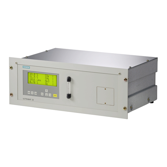
These instructions are valid for the 19" rack units of Series 6 and the ULTRAMAT 23 gas analyzers which are available as
19" rack unit as well as bench-top unit. This includes the devices listed below:
● ULTRAMAT 23
● ULTRAMAT 6E
● ULTRAMAT/OXYMAT 6E
● OXYMAT 6E
● OXYMAT 61
● OXYMAT 64
● CALOMAT 6E
● CALOMAT 62E
● FIDAMAT 6
These gas analyzers are suitable for a wide variety of measurements and are also available in different versions. The data
on the label, among others, indicates which device version you have.
© Siemens AG 2018. All rights reserved
A5E45779144002-01, 09/2018
1

Advertisement

Table of Contents
loading

Summary of Contents for Siemens 6 Series

  • Page 1 These gas analyzers are suitable for a wide variety of measurements and are also available in different versions. The data on the label, among others, indicates which device version you have. © Siemens AG 2018. All rights reserved A5E45779144002-01, 09/2018...
  • Page 2 We are using the label of an ULTRAMAT 23 as an example. Data matrix code Disposal information: Do not dispose with household waste! CE conformity symbol Name and address of manufacturer Designation of origin Measuring range(s) Serial number Order No. (MLFB number) of the device Device name Figure 1-1 ULTRAMAT 23 label (example)
  • Page 3: General Information

    For further information, or in the case of problems which are not covered in enough detail in this document, please request the required information from your local or responsible Siemens regional office. Special information and warnings This manual provides you with information on commissioning, installing, operating, and maintaining the device.
  • Page 4: Notes On Warranty

    The contents of this manual shall not become part of or modify any prior or existing agreement, commitment or legal relationship. The sales contract contains all obligations on the part of Siemens as well as the complete and solely applicable warranty conditions.
  • Page 5: Safety Instructions

    Operation under special ambient conditions We highly recommend that you contact your Siemens representative or our application department before you operate the device under special ambient conditions as can be encountered in nuclear power plants or when the device is used for research and development purposes.
  • Page 6 WARNING Improper device modifications Risk to personnel, system and environment can result from modifications to the device, particularly in hazardous areas. Only carry out modifications that are described in the instructions for the device. Failure to observe this requirement • cancels the manufacturer's warranty and the product approvals.
  • Page 7: Analyzers In Hazardous Areas

    Analyzers in hazardous areas WARNING Unsuitable device for the hazardous area Danger of explosion. Only use equipment that is approved for use in the intended hazardous area and labelled accordingly. • The sample gas exhaust lines must terminate outside the hazardous area at a harmless location. The sample gas exhaust line can also be returned to the sampling point.
  • Page 8: Analyzers In Biogas Plants

    Analyzers in biogas plants DANGER Danger of poisoning The ULTRAMAT 23 is used, among other things, for the measurement of hydrogen sulfide (hydrogen sulfide, dihydrogen sulfide, H Hydrogen sulfide is highly toxic even in small concentrations! The odor threshold for hydrogen sulfide is very low at 0.02 vpm (20 vpb), but higher concentrations result in numbing of the olfactory receptors in the nose so that the odor is no longer perceived.
  • Page 9: Installation Location Requirements

    Installation location requirements CAUTION Direct sunlight Device damage. The device can overheat or materials become brittle due to UV exposure. Protect the device from direct sunlight. • Make sure that the maximum permissible ambient temperature is not exceeded. Refer to the information in Technical •...
  • Page 10 FM and CSA The following table contains the instructions and requirements for use of gas analyzers certified in accordance with CSA and FM guidelines in hazardous areas of Class 1, Division 2 and Class 1, Zone 2. Require- FM/CSA Class 1, Division 2 FM/CSA Class 1, Zone 2 ment for Encapsula-...
  • Page 11 Connecting Safety instructions 4.1.1 General Observe the safety rules, provisions and laws applicable in your country during connection, assembly and operation. These include, for example: ● National Electrical Code (NEC - NFPA 70) (USA) ● Canadian Electrical Code (CEC) (Canada) Further provisions for hazardous area applications are for example: ●...
  • Page 12: Electrical Connection

    4.1.2 Analyzers in hazardous areas DANGER Explosion hazard If a flammable or ignitable atmosphere exists, plugs must never be disconnected or lamps/fuses replaced when the analyzer is supplied with power. DANGER Potentially explosive atmosphere The analyzer keys must not be pressed if a potentially explosive atmosphere may be present. If operation using the keyboard is necessary, a hot work permit is absolutely essential.
  • Page 13 19" rack unit A flexible cable suitable for power supply cords must be connected to the appliance plug. The cross-section of each conductor must be at least 1 mm . The cross-section of the PE conductor must not be smaller than that of the L and N conductors.
  • Page 14: Connection Of The Signal Lines

    4.2.2 Connection of the signal lines NOTICE Incorrect power supply The 24 V/1 A power supply must be a power-limited safety extra-low voltage with safe electrical isolation (SELV). Only connect the signal lines to devices which also have reliable electric isolation from their power supply. ●...
  • Page 15 4.2.3 PROFIBUS DP Figure 4-2 PROFIBUS DP connection CAUTION Pin 7 is connected to the data line. No consumers must be connected. The cable shield must be connected over a larger surface in the plug housing. Failure to comply with this can result in personal injury or damage to property. Compact Operating Instructions in accordance with EN 61010-1 and EN 60079-0 A5E45779144002-01, 09/2018...
  • Page 16: Pin Assignments

    4.2.4 Pin assignments ULTRAMAT 23 Motherboard Figure 4-3 ULTRAMAT 23 motherboard Compact Operating Instructions in accordance with EN 61010-1 and EN 60079-0 A5E45779144002-01, 09/2018...
  • Page 17 Optional board Figure 4-4 ULTRAMAT 23 optional board Compact Operating Instructions in accordance with EN 61010-1 and EN 60079-0 A5E45779144002-01, 09/2018...
  • Page 18 CALOMAT 6E Motherboard Figure 4-5 Pin assignments of CALOMAT 6E motherboard Compact Operating Instructions in accordance with EN 61010-1 and EN 60079-0 A5E45779144002-01, 09/2018...
  • Page 19: Gas Connections

    AUTOCAL board Figure 4-6 AUTOCAL module of CALOMAT 6E Gas connections 4.3.1 Gas preparation To prevent contamination of parts through which the sample gas flows, the sample gas must be prepared appropriate to the measurement. We recommend the following minimum configuration: ●...
  • Page 20: Connection Diagrams

    4.3.3 Toxic and corrosive gases Appropriate components must be used for toxic and/or flammable gases. These components must be approved for the respective application. We recommend that you consult our technical department before connecting toxic or corrosive gases. Please note in particular that the control cabinet housing the analyzer must have a protection rating of at least IP54 and be purged with a suitable purging gas.
  • Page 21 CALOMAT 6E When installing in a cabinet, mount analyzer on support rails or telescopic rails RS485 9-pin connector 15-pin connector, relay outputs and binary inputs 25-pin connector, analog inputs and outputs 9-pin interface connector for PROFIBUS (option) 37-pin connector, relay outputs and binary inputs Network connection and fine fuses (option) Figure 4-9...
  • Page 22: General Information On Commissioning

    WARNING Commissioning and operation with pending error If an error message appears, correct operation in the process is no longer guaranteed. Check the gravity of the error. • Correct the error. • If the error still exists: • – Take the device out of operation. –...
  • Page 23: Service And Maintenance

    Before opening or removing the device ensure that process media cannot be released. • WARNING Impermissible repair and maintenance of the device Repair and maintenance must be carried out by Siemens authorized personnel only. • CAUTION Dangerous voltage at open device Danger of electric shock when the enclosure is opened or enclosure parts are removed.
  • Page 24 WARNING Hot surfaces There is a danger of burns resulting from hot surfaces when the device is open. This is indicated by the corresponding warning symbol on the device. Take appropriate protective measures, for example, wear protective gloves. • Wait at least 60 minutes before you start working on hot analyzer parts. •...
  • Page 25: Replacing Fuses

    WARNING Maintenance during continued operation in a hazardous area There is a danger of explosion when carrying out repairs and maintenance on the device in a hazardous area. Isolate the device from power. • - or - Ensure that the atmosphere is explosion-free (hot work permit). •...
  • Page 26: Technical Specifications

    Technical specifications General technical data The general technical specifications apply to all analyzer versions unless they are not defined otherwise in the technical specifications of the analyzer versions. The technical specifications listed in this document are an excerpt that includes all safety-related data. The complete technical specifications can be found in the respective operating instructions of your analyzer.
  • Page 27 Technical specifications ULTRAMAT 23 Enclosure Weight Approx. 10 kg The weight varies according to the ordered variant. Dimensions (W x D x H) 19" rack unit • 483 mm x 378 mm x 177 mm Bench-top unit • 529 mm x 342 mm x 170 mm Electrical characteristics Power consumption Max.
  • Page 28 Parts in gas path wetted by sample gas 19" rack unit Bench-top unit (only IR + ec O With hoses Condensation trap at gas PA6 (polyamide) inlet Condensation trap PE (polyethylene) Gas connections 6 mm PA6 (polyamide) PA6 (polyamide) Gas connections ¼" Stainless steel 1.4571 Stainless steel 1.4571 Hose...
  • Page 29 Electrical characteristics Fuse values 1-channel unit (7MB2121, 7MB2127, 7MB2124, 7MB2126) • – 100 to 120 V 1T/250 – 200 to 240 V 0.63T/250 2-channel unit (7MB2123, 7MB2128, 7MB2124, 7MB2126) • – 100 to 120 V 1.6 T/250 – 200 to 240 V 1T/250 Gas inlet conditions Permissible sample gas pressure...
  • Page 30 Parts in gas path wetted by sample gas Angle pieces Pressure switch sample gas Diaphragm Enclosure PA 6.3 T Technical specifications OXYMAT 6E, OXYMAT channel in OXYMAT/ULTRAMAT 6E and OXYMAT 61 Enclosure Weight Approx. 13 kg Dimensions 483 mm x 385 mm x 172 mm (W x D x H) Electrical characteristics Power consumption (analyzer) Approx.
  • Page 31 Parts in gas path wetted by sample gas Enclosure PA 6.3 T Technical specifications OXYMAT 64 Enclosure Weight Approx. 11 kg Dimensions 483 mm x 356 mm x 173 mm (W x D x H) Parts in gas path wetted by sample gas Gas connections Stainless steel 1.4571 Gaskets (O–rings)
  • Page 32 Parts in gas path wetted by sample gas Gas connections Stainless steel 1.4571, pipe diameter 1/4" or 6 mm Gaskets (O–rings) FFKM (e.g. Chemraz) Sensor Silicon, SiO , gold, epoxy resin, glass Measuring cell body Stainless steel 1.4571 Internal gas path (gas lines) Stainless steel 1.4571 Leak-tightness Loss through leaks <...
  • Page 33 Technical specifications FIDAMAT 6 Enclosure Weight Approx. 23 kg Dimensions (W x D x H) 483 mm x 457 mm x 160 mm Electrical characteristics Power consumption Approx. 150 VA during operation Approx. 350 VA in the warm-up phase Fuse values 100 to 120 V •...
  • Page 34: Taking Out Of Operation And Disposal

    Taking out of operation and disposal Repair or changing of location If the analyzer is shut down for repair or for changing the location of use, proceed as follows: DANGER When the device is used in hazardous areas A hot work permit is required for hazardous areas. 1.
  • Page 35: Service And Support

    Appendix Service and support Technical support is available on the Internet at: Services & Support (https://support.industry.siemens.com/cs/gb/en/sc) Your regional Siemens representative can be found here: Contact partner (https://w3.siemens.com/aspa_app/) ESD directives NOTICE Electrostatic sensitive devices can be destroyed by voltages which are far below the human perception limit. These voltages already occur if you touch a component or the electric connections of a module without being electrostatically discharged.
  • Page 36: List Of Abbreviations

    Resistor, Capacitor; switch which consists of an ohmic resistor and a capacitor. SELV Safety Extra Low Voltage SIPROM GA Siemens Process Maintenance for Gas Analyzers TÜV Technischer Überwachungsverein, German Technical Inspectorate ULTRAMAT 6 Lower Explosion Limit Verband der Elektrotechnik, Elektronik und Informationstechnik (German Association for Electrical,...

Table of Contents