Siemens ULTRAMAT 23 Manual
Continuous gas analysis
gas analyzer for measuring ir-absorbing gases,
oxygen and hydrogen sulfide
Hide thumbs
Also See for ULTRAMAT 23:
- Operating instructions manual (168 pages) ,
- Product information (22 pages) ,
- Manual (140 pages)

Related Manuals for Siemens ULTRAMAT 23


Summary of Contents for Siemens ULTRAMAT 23
- Page 1 Continuous gas analysis Gas analyzer for measuring IR-absorbing gases, oxygen and hydrogen sulfide ULTRAMAT 23 Manual Edition 03/2016 Answers for industry.
- Page 3 ___________________ ULTRAMAT 23 Introduction ___________________ Safety instructions ___________________ Continuous gas analysis Description ___________________ installation Gas analyzer for measuring IR- absorbing gases, oxygen, and ___________________ hydrogen sulfide Connecting ULTRAMAT 23 ___________________ Commissioning Manual ___________________ Operation ___________________ Functions ___________________ Application note ___________________...
- Page 4 Note the following: WARNING Siemens products may only be used for the applications described in the catalog and in the relevant technical documentation. If products and components from other manufacturers are used, these must be recommended or approved by Siemens. Proper transport, storage, installation, assembly, commissioning, operation and maintenance are required to ensure that the products operate safely and without any problems.
-
Page 5: Table Of Contents
Connection diagrams ......................52 3.5.4 Pin assignments ........................54 Dimensional drawings ......................56 Communication ........................57 3.7.1 PROFIBUS DP/PA ........................57 3.7.2 General information ........................ 59 3.7.3 ELAN interface ........................60 3.7.4 SIPROM GA ..........................61 ULTRAMAT 23 Manual, 3/2016, A5E37100388-003... - Page 6 Commissioning........................82 6.4.2 AUTOCAL ..........................82 6.4.3 Initial calibration ........................83 System setup with several analyzers in parallel ..............84 Operation .............................. 89 General information ....................... 89 User prompting........................90 Display and control panel ....................... 91 ULTRAMAT 23 Manual, 3/2016, A5E37100388-003...
- Page 7 Calibration: H2S sensor: Enter TC parameters ..............120 8.2.6 Calibration: Pressure sensor ....................121 8.2.7 Calibration: AUTOCAL/drift values ..................122 8.2.7.1 Calibration: AUTOCAL/drift values: Drift values ..............122 8.2.7.2 Calibration: AUTOCAL/drift values: Cycle time ..............123 ULTRAMAT 23 Manual, 3/2016, A5E37100388-003...
- Page 8 10.2.4 Replacing fuses........................168 10.2.5 Replacing the fine safety filter ....................169 10.2.6 Maintenance work on the bench-top unit ................170 10.2.6.1 Emptying the condensation trap ..................170 10.2.6.2 Replacing the coarse filter ....................170 ULTRAMAT 23 Manual, 3/2016, A5E37100388-003...
- Page 9 Returned delivery ........................226 A.4.1 Return address ........................227 A.4.2 Error Description ........................227 A.4.3 Decontamination declaration ....................228 ESD directives ............................ 231 ESD guidelines ........................231 List of abbreviations ..........................233 List of abbreviations ......................233 ULTRAMAT 23 Manual, 3/2016, A5E37100388-003...
- Page 10 Table of contents Index ..............................239 ULTRAMAT 23 Manual, 3/2016, A5E37100388-003...
-
Page 11: Introduction
Product versions The ULTRAMAT 23 gas analyzer is suitable for a wide variety of measurements and is therefore available in different versions. The data on the label, among others, indicates which device version you have. -
Page 12: General Information
For further information, or in the case of problems which are not covered in enough detail in this document, please request the required information from your local or responsible Siemens regional office. Note In particular, before using the device for new research and development applications, we recommend that you first contact us to discuss the application in question. -
Page 13: Qualified Personnel
● For explosion-proof devices: they are authorized, trained, or instructed in carrying out work on electrical circuits for hazardous systems. ● They are trained or instructed in maintenance and use of appropriate safety equipment according to the safety regulations. ULTRAMAT 23 Manual, 3/2016, A5E37100388-003... -
Page 14: Warranty Conditions
All obligations on the part of Siemens AG are contained in the respective sales contract, which also contains the complete and solely applicable liability provisions. The provisions defined in the sales contract for the responsibility for defects are neither extended nor limited by the remarks in this document. -
Page 15: Safety Instructions
Siemens undergo continuous development with this factor in mind. Siemens strongly recommends that you regularly check for product updates. For the safe operation of products and solutions from Siemens, it is necessary to take suitable protective measures (e.g. cell protection concept) and to integrate each component into an overall IT security concept which corresponds to state-of-the-art IT technology. - Page 16 To prevent the danger of poisoning or damage to parts of the analyzer, the analyzer or the system must be purged with inert gas (e.g. nitrogen). The gas displaced by purging must be collected using appropriate equipment and disposed of environmentally-friendly via an exhaust line. ULTRAMAT 23 Manual, 3/2016, A5E37100388-003...
-
Page 17: Analyzers In Biogas Plants
Analyzers in hazardous areas WARNING Unsuitable device for the hazardous area Danger of explosion. • Only use equipment that is approved for use in the intended hazardous area and labelled accordingly. ULTRAMAT 23 Manual, 3/2016, A5E37100388-003... - Page 18 Safety instructions 2.2 Analyzers in hazardous areas ULTRAMAT 23 Manual, 3/2016, A5E37100388-003...
-
Page 19: Description
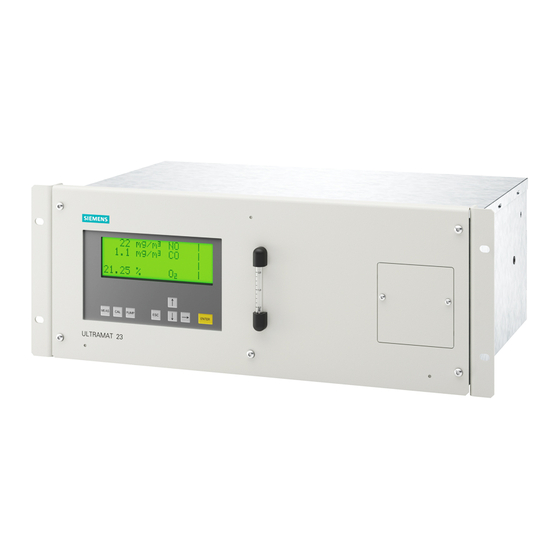
Area of application Overview Up to 4 gas components can be measured continuously and simultaneously with the ULTRAMAT 23 gas analyzer. The analyzer has an infrared detector for infrared-sensitive gases such as CO, N O or CH , and can be optionally fitted with up to two further... - Page 20 Description 3.1 Area of application Figure 3-1 Front view of ULTRAMAT 23 for measurement of CO, NO, and O (example of rack unit) Areas of application ● Optimization of small firing systems ● Monitoring of exhaust gas concentration from firing systems with all types of fuel (oil, gas and coal) as well as operational measurements with thermal incineration plants ●...
- Page 21 ● Chemical plants ● Cement industry Special versions ● The ULTRAMAT 23 with 2 IR components without pump is also available with two separate gas paths. This allows the measurement of two measuring points as used e.g. for the NO measurement before and after the NO converter.
-
Page 22: Design
Control and function keys for operation. Figure 3-2 Design of ULTRAMAT 23 as 19" rack unit The ULTRAMAT 23 is also available as a bench-top unit. This version differs from the rack unit shown here as follows: ● Closed housing without mounting frame. -
Page 23: Ultramat
● Integrated sample gas pump with bench-top unit, available as option for rack unit (not with piped gas paths) ● Gas connections for sample gas inlet and outlet as well as zero gas possible with pipe diameter 6 mm or ¼" ● Gas and electrical connections at the rear. ULTRAMAT 23 Manual, 3/2016, A5E37100388-003... - Page 24 Scrolling back in menu or cancellation of an input. ⑧ Switching on and off of internal pump, pumping capacity adjustable using menu. ⑨ Key for starting AUTOCAL. ⑩ Immediate return to measuring mode. Figure 3-3 Operator panel of the ULTRAMAT 23 ULTRAMAT 23 Manual, 3/2016, A5E37100388-003...
- Page 25 ELAN (RS485) present in basic unit. Options: ● RS485/USB converter ● RS485/RS232 converter ● RS485/Ethernet converter ● Incorporation in networks via PROFIBUS DP/PA interface (via option board) ● SIPROM GA software as servicing and maintenance tool ULTRAMAT 23 Manual, 3/2016, A5E37100388-003...
-
Page 26: Function
Description 3.3 Function Function Several independent measuring principles which work selectively may be present in the ULTRAMAT 23. These are described below. Infrared measurement Capillary IR source Second detector layer Reflector Microflow sensor Window Analyzer chamber Slide Chopper wheel First detector layer... - Page 27 Electrochemical oxygen measurement Gold cathode Signal output Electrolyte (acetic acid) Lead anode Thermistor and load resistor for tempera- Oxygen diffusion membrane made of FEP ture compensation Figure 3-5 Operating principle of the electrochemical O sensor ULTRAMAT 23 Manual, 3/2016, A5E37100388-003...
- Page 28 < 5% or every two months in the case of all larger measuring ranges. ULTRAMAT 23 Manual, 3/2016, A5E37100388-003...
- Page 29 Figure 3-8 Calibration The ULTRAMAT 23 can be calibrated using, for example, ambient air. During this process (between 1 and 24 hours (adjustable), 0 = no AUTOCAL), the analyzer chamber is purged with air. The detector then generates the largest signal U (no pre-absorption in the analyzer chamber).
- Page 30 The tolerance range between two or more AUTOCAL procedures can be individually parameterized on the ULTRAMAT 23 and a warning output in the event of deviations. A fault message is output when the value falls below the original factory setting of <...
-
Page 31: Technical Specifications
Approx. 10 kg (22 lbs.) The weight varies according to the ordered vari- ant. Degree of protection IP40 in accordance with EN 60529 for the versions 7MB235x (TÜV) IP20 in accordance with EN 60529 for the versions 7MB233x (standard) ULTRAMAT 23 Manual, 3/2016, A5E37100388-003... - Page 32 < 90% RH (relative humidity) during transportation and storage (Delivery information (Page 14)) Permissible ambient pressure See specific technical specifications for IR detector/sensors (Infrared detector (Page 35)) Maximum operating altitude 2000 m above sea level Pollution degree ULTRAMAT 23 Manual, 3/2016, A5E37100388-003...
- Page 33 0 ... 50 °C (32 ... 122 °F) Sample gas humidity < 90 % RH (relative humidity), non-condensing Note Since measuring ranges can be changed, all accuracy data applies to the ranges specified on the label! ULTRAMAT 23 Manual, 3/2016, A5E37100388-003...
-
Page 34: Parts In Gas Path Wetted By Sample Gas
Operation of analyzers in hazardous areas For safe operation of the analyzer in hazardous areas, it is essential to observe the information and conditions referred to in "Information pursuant to ATEX for use in hazardous areas" (Order No.: A5E37888334) ULTRAMAT 23 Manual, 3/2016, A5E37100388-003... -
Page 35: Infrared Detector
-20 ... +60 °C (-4 ... 140 °F) During transportation and storage • Permissible ambient humidity < 90% RH (relative humidity) during transportation and storage Permissible ambient pressure 600 ... 1200 hPa absolute Maximum operating altitude 2000 m above sea level ULTRAMAT 23 Manual, 3/2016, A5E37100388-003... - Page 36 The device must be operated at a constant ambient temperature. The device must not be operated in an area subject to drafts. This is especial- ly valid for the rear panel with large cooling element. Other This measuring range has not been suitability-tested. ULTRAMAT 23 Manual, 3/2016, A5E37100388-003...
- Page 37 • The specified maintenance intervals refer to the Set CEM CERT systems. • Also refer to the current certificates in accordance with EN 15267. • The current certificates can always be found on the Internet at: Approvals and certificates (https://support.industry.siemens.com/cs/de/en/ps/17728) ULTRAMAT 23 Manual, 3/2016, A5E37100388-003...
-
Page 38: Electrochemical Oxygen Sensor
-20 ... +60 °C (-4 ... 140 °F) During transportation and storage • Permissible ambient humidity < 90% RH (relative humidity) during transportation and storage Permissible ambient pressure 600 ... 1200 hPa absolute Maximum operating altitude 2000 m above sea level ULTRAMAT 23 Manual, 3/2016, A5E37100388-003... -
Page 39: Paramagnetic Oxygen Sensor
Permissible operating temperature 5 ... 45 °C (41 ... 113 °F) Measuring response Response time (T time) <60 s Output signal noise < 1% of smallest measuring range Reproducibility ≤ 1% of smallest measuring range ULTRAMAT 23 Manual, 3/2016, A5E37100388-003... - Page 40 Dinitrogen monoxide - 0.20 - 0.22 Ethane - 0.43 - 0.47 Ethyl benzene - 1.89 - 2.08 Ethylene, ethene - 0.20 - 0.22 Ethylene glycol - 0.78 - 0.88 Ethylene oxide - 0.54 - 0.60 ULTRAMAT 23 Manual, 3/2016, A5E37100388-003...
- Page 41 - 1.63 - 1.80 Toluene - 1.57 - 1.73 Vinyl chloride -0.68 - 0.74 Vinyl fluoride - 0.49 - 0.54 Water (vapor) - 0.03 - 0.03 Hydrogen + 0.23 + 0.26 Xenon - 0.95 - 1.02 ULTRAMAT 23 Manual, 3/2016, A5E37100388-003...
-
Page 42: Hydrogen Sulfide Sensor
< 3%/10 K referred to full-scale value Air pressure < 0.2 % of measured value per 1% pressure change Note Measuring ranges The exact specification of the largest and smallest H S ranges can be found on the label! ULTRAMAT 23 Manual, 3/2016, A5E37100388-003... -
Page 43: Wiring Diagrams
17 Atmospheric pressure sensor 18 Hydrogen sulfide sensor 19 Oxygen sensor (paramagnetic) The variant with specially cleaned gas path (Cleaned for O2) -B06) does not contain a fine safety filter in the sample gas path. ULTRAMAT 23 Manual, 3/2016, A5E37100388-003... - Page 44 Description 3.5 Wiring diagrams Figure 3-9 ULTRAMAT 23, bench-top unit with internal sample gas pump, condensation trap and fine safety filter on front plate; optional oxygen measurement ULTRAMAT 23 Manual, 3/2016, A5E37100388-003...
- Page 45 Description 3.5 Wiring diagrams Figure 3-10 ULTRAMAT 23, 19" rack unit enclosure with internal sample gas pump; optional oxygen measurement ULTRAMAT 23 Manual, 3/2016, A5E37100388-003...
- Page 46 Description 3.5 Wiring diagrams Figure 3-11 ULTRAMAT 23, 19" rack unit enclosure without internal sample gas pump; optional oxygen measurement ULTRAMAT 23 Manual, 3/2016, A5E37100388-003...
- Page 47 Description 3.5 Wiring diagrams Figure 3-12 ULTRAMAT 23, 19" rack unit enclosure without internal sample gas pump; with separate gas path for further IR components; optional oxygen measurement Figure 3-13 ULTRAMAT 23, 19" rack unit enclosure without internal sample gas pump; sample gas path as pipes without safety filter or safety condensation trap;...
- Page 48 Description 3.5 Wiring diagrams Figure 3-14 ULTRAMAT 23, 19" rack unit enclosure with internal sample gas pump and hydrogen sulfide sensor ULTRAMAT 23 Manual, 3/2016, A5E37100388-003...
- Page 49 Description 3.5 Wiring diagrams Figure 3-15 ULTRAMAT 23, 19" rack unit enclosure with hydrogen sulfide sensor without internal sample gas pump ULTRAMAT 23 Manual, 3/2016, A5E37100388-003...
- Page 50 Description 3.5 Wiring diagrams Figure 3-16 ULTRAMAT 23, 19" rack unit enclosure with internal sample gas pump and paramagnetic oxygen sensor ULTRAMAT 23 Manual, 3/2016, A5E37100388-003...
-
Page 51: Gas Connections
Description 3.5 Wiring diagrams 3.5.2 Gas connections Figure 3-17 Gas connections of ULTRAMAT 23 versions The positions of the connections on the devices are shown in the connection diagrams in section Connection diagrams (Page 52). ULTRAMAT 23 Manual, 3/2016, A5E37100388-003... -
Page 52: Connection Diagrams
-X45: ELAN (RS485) 9-pin connector ④ -X90: 9-pin interface connector (option board with PROFIBUS-DP/PA) ⑤ -X50: 37-pin connector: Option board; binary inputs/relay outputs ⑥ -X80: 37-pin connector: Analog and digital inputs and outputs Figure 3-18 Connections of bench-top unit ULTRAMAT 23 Manual, 3/2016, A5E37100388-003... - Page 53 -X50: 37-pin connector: Option board; binary inputs/relay outputs ⑥ -X80: 37-pin connector: Analog and digital inputs and outputs When installing in a cabinet, mount analyzer on support rails or telescopic rails Figure 3-19 Connections of rack device ULTRAMAT 23 Manual, 3/2016, A5E37100388-003...
-
Page 54: Pin Assignments
Description 3.5 Wiring diagrams 3.5.4 Pin assignments Pin assignments of the motherboard Figure 3-20 ULTRAMAT 23 motherboard ULTRAMAT 23 Manual, 3/2016, A5E37100388-003... - Page 55 Description 3.5 Wiring diagrams Add-on board Figure 3-21 ULTRAMAT 23 add-on board ULTRAMAT 23 Manual, 3/2016, A5E37100388-003...
-
Page 56: Dimensional Drawings
Dimensional drawings Rack unit Gas connec- Pipe nozzle diameter 6 mm or 1/4" tions: Important: When installing in a bench-top enclosure or cabinet, only mount analyzer on support rails. Figure 3-22 Dimensional drawings of rack unit ULTRAMAT 23 Manual, 3/2016, A5E37100388-003... -
Page 57: Communication
3.7.1 PROFIBUS DP/PA PROFIBUS DP/PA is the leading fieldbus on the market. All Siemens gas analyzers with an optional – also retrofittable – plug-in card are Profibus-compatible and comply with the binding "Device profile for analyzers" defined by the PNO (PROFIBUS International). Central access to the system analyzers is possible with the SIMATIC PDM software tool. - Page 58 All gas analyzers of Series 6 (ULTRAMAT 6, OXYMAT 6/61/64, CALOMAT 6/62 and FIDAMAT 6 as well as ULTRAMAT 23) are PROFIBUS-compatible with an optional plug-in card, which can also be retrofitted.
-
Page 59: General Information
3.7 Communication Figure 3-24 Typical structure of a PROFIBUS system 3.7.2 General information All gas analyzers of series 6 as well as the ULTRAMAT 23 offer the following communication facilities: ● ELAN interface (RS485) ● SIPROM GA ● PROFIBUS DP/PA ●... -
Page 60: Elan Interface
RS485 to RS232/USB/Ethernet converter with connecting cable RS485 bus connector with jumper Analyzer RS485 cable RS485 bus connector RS485 network 9-pin Sub-D plug Optional: RS485 repeater Figure 3-25 Typical structure of an ELAN network (RS485) ULTRAMAT 23 Manual, 3/2016, A5E37100388-003... -
Page 61: Siprom Ga
Functions: ● Display and storage of device data ● Remote operation of device functions ● Parameter and configuration settings ● Comprehensive diagnostics information ● Remote calibration ULTRAMAT 23 Manual, 3/2016, A5E37100388-003... -
Page 62: Upgrading Options
It is possible to upgrade the device firmware of older gas analyzers using the SIPROM GA software. Details can be found in the following table. Firmware upgrades for older analyzers Article No. ULTRAMAT 23 (prior to SW version 2.06) (all languages) C79451-A3494-S501 ULTRAMAT 23 Manual, 3/2016, A5E37100388-003... -
Page 63: Installation
Even weaker vibrations influence the result! The analyzer must therefore only be used at a location which is free of vibration. Please observe the data in the Technical specifications. (Page 31) ULTRAMAT 23 Manual, 3/2016, A5E37100388-003... - Page 64 DANGER Explosion hazard The ULTRAMAT 23 gas analyzers for use in Ex zone 2 must be installed in a lockable enclosure. This enclosure must comply with the requirements of EN 60079-15 and must be designed for all ambient conditions which can occur during operation. This enclosure only be opened using a tool (e.g.
- Page 65 Note In the case of device versions for use in Ex zone 2, it is also essential to observe the 'ATEX compact operating instructions for rack units of Series 6' (A5E37888334)! ULTRAMAT 23 Manual, 3/2016, A5E37100388-003...
- Page 66 ULTRAMAT 23 Manual, 3/2016, A5E37100388-003...
-
Page 67: Connecting
Operation of analyzers in hazardous areas For safe operation of the analyzer in hazardous areas, it is essential to observe the information and conditions referred to in "Information pursuant to ATEX for use in hazardous areas" (Order No.: A5E37888334) ULTRAMAT 23 Manual, 3/2016, A5E37100388-003... -
Page 68: Electrical Circuit Breaker In Accordance With Iec 60947-1
• Power plug: Ensure that the used socket has a PE/ground conductor connection. Check that the PE/ground conductor connection of the socket and power plug match each other. • Connecting terminals: Connect the terminals according to the terminal connection diagram. First connect the PE/ground conductor. ULTRAMAT 23 Manual, 3/2016, A5E37100388-003... -
Page 69: Power Supply Cable For Bench-Top Unit
DANGER Explosion hazard The ULTRAMAT 23 gas analyzers for use in Ex zone 2 must be installed in a lockable enclosure. This enclosure must comply with the requirements of EN 60079-15 and must be designed for all ambient conditions which can occur during operation. This enclosure only be opened using a tool (e.g. -
Page 70: Analyzers In Biogas Plants
Hot, toxic and corrosive media could be released if the process medium is unsuitable for the wetted parts. • Ensure that the material of the device parts wetted by the process medium is suitable for the medium. Refer to the information in Technical specifications (Page 31). ULTRAMAT 23 Manual, 3/2016, A5E37100388-003... -
Page 71: Variant With Specially Cleaned Gas Path (Cleaned For O2)
> >1 l must be installed between the analyzer and the exhaust line. ● The exhaust gas line must always be routed with a falling gradient away from the device since moisture can condense in it. ULTRAMAT 23 Manual, 3/2016, A5E37100388-003... -
Page 72: Gas Preparation
5.2.2 Gas preparation The sample gas must be sufficiently conditioned to prevent contamination of the parts through which it flows. The ULTRAMAT 23 is usually preceded by the following elements: ● Gas sampling device with filter ● Sample gas cooler ●... -
Page 73: Electrical Connection
Gas cooler Gas outlet Analyzer filter AUTOCAL/zero gas supply Sample gas pump (option) Figure 5-1 Gas conditioning in the ULTRAMAT 23 Electrical connection 5.3.1 Connection of the signal lines NOTICE Incorrect power supply The 24 V/1 A power supply must be a power-limited safety extra-low voltage with safe electrical isolation (SELV). -
Page 74: Power Connection
B5276-C176 English) for details on the interface cable. 5.3.2 Power connection NOTICE Incorrect power supply Check before connecting that the existing supply voltage corresponds to that specified on the label of the device. Install the power line separately from the signal lines. ULTRAMAT 23 Manual, 3/2016, A5E37100388-003... - Page 75 Electrical circuit breaker in accordance with IEC 60947-1 and IEC 60947-3 In accordance with IEC 60947-1 "Standard for low-voltage switchgear and controlgear" and IEC 60947-3 "Switches, disconnectors, fuses" you require an electrical circuit breaker for the device. We recommend commercially available automatic circuit breakers. ULTRAMAT 23 Manual, 3/2016, A5E37100388-003...
- Page 76 (see arrow in above picture). This bracket is enclosed loose with the analyzer and must be attached before switching on. ULTRAMAT 23 Manual, 3/2016, A5E37100388-003...
-
Page 77: Commissioning
The degree of protection specified on the nameplate or in Technical specifications (Page 31) is no longer guaranteed if the device is open or not properly closed. • Make sure that the device is securely closed. ULTRAMAT 23 Manual, 3/2016, A5E37100388-003... -
Page 78: Loss Of Degree Of Protection
For use in hazardous areas 6.2.4.1 Analyzers in hazardous areas DANGER Explosion hazard If a flammable or ignitable atmosphere exists, plugs must never be disconnected or lamps/fuses replaced when the analyzer is supplied with power. ULTRAMAT 23 Manual, 3/2016, A5E37100388-003... - Page 79 DANGER Explosion hazard The ULTRAMAT 23 gas analyzers for use in Ex zone 2 must be installed in an appropriate enclosure. This enclosure must comply with the requirements of EN 60079-15 and must be designed for all ambient conditions which can occur during operation.
-
Page 80: Use In Biogas Plants
This device is used in biogas plants, among other places. When it is used in biogas plants, you should expect that the sample gas will contain methane, which forms explosive mixtures with oxygen or air in certain concentrations. These conditions are possible with certain operating states of the plant. ULTRAMAT 23 Manual, 3/2016, A5E37100388-003... -
Page 81: Preparation For Commissioning
Refer to the associated operating instructions. 6.3.3 Device interfaces Check that all device interfaces (see Communication (Page 57)) are properly assigned and configured. ULTRAMAT 23 Manual, 3/2016, A5E37100388-003... -
Page 82: Commissioning
AUTOCAL is to be carried out with air or N , and thus whether the sensitivity (20.95 % O ) or the zero point of the sensor is calibrated. ULTRAMAT 23 Manual, 3/2016, A5E37100388-003... -
Page 83: Initial Calibration
Calibration (Page 111)). The calibration should be carried out with a gas containing a sufficient concentration of the measured component (between 70 and 100% of the full-scale value in nitrogen or synthetic air). Note The calibration gas is connected via the sample gas path. ULTRAMAT 23 Manual, 3/2016, A5E37100388-003... -
Page 84: System Setup With Several Analyzers In Parallel
SYNC and the digital input SYNC of the slave device. The simultaneous connection between the digital output SYNC of the slave device and the digital input SYNC of the master device guarantees that zero gas is always passed simultaneously through both analyzers. ULTRAMAT 23 Manual, 3/2016, A5E37100388-003... - Page 85 (see Calibration: AUTOCAL/drift values: Cycle time (Page 123)). ● Assign the "Sync." function to a relay (see Configuration: Inputs/outputs/pump: Assign relays (Page 138)). ● Assign the "AUTOCAL" function to the digital input SYNC (see Configuration: Inputs/outputs/pump: Binary/sync inputs (Page 141)). ULTRAMAT 23 Manual, 3/2016, A5E37100388-003...
- Page 86 ● Assign the "Zero gas" function to a relay (see Configuration: Inputs/outputs/pump: Assign relays (Page 138)). ● Assign the "Only CAL contact" function to the digital input SYNC (see Configuration: Inputs/outputs/pump: Binary/sync inputs (Page 141)). ULTRAMAT 23 Manual, 3/2016, A5E37100388-003...
- Page 87 (see Calibration: AUTOCAL/drift values: Cycle time (Page 123)). ● Assign the "Sync." function to a relay (see Configuration: Inputs/outputs/pump: Assign relays (Page 138)). ● Assign the "AUTOCAL" function to the digital input SYNC (see Configuration: Inputs/outputs/pump: Binary/sync inputs (Page 141)). ULTRAMAT 23 Manual, 3/2016, A5E37100388-003...
- Page 88 Commissioning 6.5 System setup with several analyzers in parallel ULTRAMAT 23 Manual, 3/2016, A5E37100388-003...
-
Page 89: Operation
CSA Class I Div. 2 and ATEX Zone 2 WARNING Potentially explosive atmosphere The analyzer keys must not be pressed if a potentially explosive atmosphere may be present. If operation using the keyboard is necessary, a hot work permit is absolutely essential. ULTRAMAT 23 Manual, 3/2016, A5E37100388-003... -
Page 90: User Prompting
Operation 7.2 User prompting User prompting In the next sections, operation of the ULTRAMAT 23 is explained according to the following scheme: Figure 7-1 User prompting The heading of the respective section indicates the complete menu path, starting from the main menu, on which the shown display can be reached (see section Display and control panel (Page 91)). -
Page 91: Display And Control Panel
The display brightness is reduced after approx. 30 minutes without an operation. This serves for energy saving and has no influence on the other properties of the device. The display becomes bright again when you continue with operation. ULTRAMAT 23 Manual, 3/2016, A5E37100388-003... - Page 92 S probe, the following statuses can be displayed at the position for the fault which is no longer present Protection function of H S probe running (display lights up permanently) Protection function of H S probe running, H S meas- ured value is invalid (display flashes) ULTRAMAT 23 Manual, 3/2016, A5E37100388-003...
-
Page 93: User Interface
7.3 Display and control panel 7.3.2 User interface The ULTRAMAT 23 has a menu-based user interface. The menu structures can always be represented as follows: MAIN MENU → Submenu 1 → Submenu 2 → Submenu 3 → Submenu 4. The following Fig. -
Page 94: Key Assignments
Operation 7.4 Operating modes 7.3.3 Key assignments Eight keys are available for operating the ULTRAMAT 23. These keys have the following meanings: No. Designation Description Function MEAS Measure Measure; abort input operations; leave input mode (from any menu level); switch from input mode to measuring mode and... -
Page 95: Warm-Up Phase
Warm-up phase Figure 7-4 Warm-up phase, measuring mode, and input mode Immediately following switching-on, the ULTRAMAT 23 tests the display elements. During this test, all elements light up simultaneously for approx. five seconds. The adjacent display subsequently appears with the remaining warm-up period which is counted down in seconds to 00:00 (minutes:seconds). -
Page 96: Measuring Mode
Once you have selected input mode, the first menu to appear is the main menu which displays four menu items. You can use these to select the individual input functions of the ULTRAMAT 23: Analyzer status With these functions you can call submenus which provide information on the analyzer status, e.g. -
Page 97: Code Levels
7.4.3.1 Code levels The ULTRAMAT 23 is provided with two code levels to protect against unauthorized or unintentional inputs. As soon as you call a function protected by a code for the first time, you will be requested to enter the three-digit code. -
Page 98: Key Operations Step By Step
<MEAS> key in measuring mode. 7.4.3.2 Key operations step by step This section describes operation of the analyzer with the keys of the operator panel using an example. ULTRAMAT 23 Manual, 3/2016, A5E37100388-003... - Page 99 • Close the code input by pressing the < ENTER> key. The initial display of the "Parameters" submenu appears. Press the <ENTER> again to call the "Measuring ranges" sub- menu. ULTRAMAT 23 Manual, 3/2016, A5E37100388-003...
- Page 100 – or return to measuring mode using <↑> or <→> and subsequently <ENTER>, where all modifications are imported which you have made since the last decoding operation, – or return to measuring mode using <↓> and <ENTER> without importing the modifications.. ULTRAMAT 23 Manual, 3/2016, A5E37100388-003...
-
Page 101: The Esc Key
Operation 7.4 Operating modes Once you have carried out the above sequence on the analyzer, you are already acquainted with the important points for operation of the ULTRAMAT 23. 7.4.3.3 The ESC key You can trigger two different functions by pressing the <ESC> key: ●... -
Page 102: The Pump Key
Configuration: Inputs/outputs/pump: Pump at CAL/MEAS (Page 142)). In addition to use of the <PUMP> key, the pump can also be switched on and off via the binary input. The binary input has priority over the key. ULTRAMAT 23 Manual, 3/2016, A5E37100388-003... -
Page 103: Functions
This display applies to an analyzer without H S probe and without paramagnetic O probe. The differences when using analyzers with one of these probes are described in section Diagnostics: Diagnostics values (Page 107). ULTRAMAT 23 Manual, 3/2016, A5E37100388-003... -
Page 104: Diagnostics: Status
8.1.1 Diagnostics: Status In this menu you can call all status messages of the ULTRAMAT 23 via further submenu items. In this example, the status of the O sensor is shown in the last line. If the analyzer is equipped with software for operating an... -
Page 105: Analyzer Status: Status: Maintenance Request
• Max. allowed is the maximum permissible value for the deviation. Refer to section Configuration: Special functions: AUTOCAL deviation (Page 144) for setting the maximum value. This function is specific to the component. ULTRAMAT 23 Manual, 3/2016, A5E37100388-003... -
Page 106: Analyzer Status: Status: O2 Sensor Status
• The reading (actual value) is the sensor sensitivity measured during the last sensitivity calibration. • The warning (maintenance request) and fault are the two minimum values where a maintenance request or fault message is output when fallen below. ULTRAMAT 23 Manual, 3/2016, A5E37100388-003... -
Page 107: Diagnostics: Diagnostics Values
T in the bottom line corresponds to the temperature of the analyzer unit, TS the temperature of the IR source (empty field = function not yet implemented, "*****" = no measured value present). ULTRAMAT 23 Manual, 3/2016, A5E37100388-003... -
Page 108: Analyzer Status: Diagnostics Values: (Electrochemical) O2 Sensor
This dialog displays the diagnostics values of the paramagnet- ic oxygen sensor (option). Meaning: • Sensorsig is the current voltage of the O sensor in mV • O is the current oxygen value. Negative values are also possible here ULTRAMAT 23 Manual, 3/2016, A5E37100388-003... -
Page 109: Analyzer Status: Diagnostics Values: H2S Sensor
– Raw voltage: This is the raw voltage following the rectification – Source 1, Source 2: Data on the IR source voltage(s), in Volt. An empty value indicates that the corresponding source does not exist. ULTRAMAT 23 Manual, 3/2016, A5E37100388-003... -
Page 110: Analyzer Status: Factory Settings Hardware
The hardware configuration and release version can be read here. 8.1.4 Analyzer status: Factory settings software Factory settings are parameters which are already set on de- livery such as • Software/firmware release version The software release version can be read here. ULTRAMAT 23 Manual, 3/2016, A5E37100388-003... -
Page 111: Calibration
In this function group you can use one or more calibration gases to calibrate the IR channels of the ULTRAMAT 23 and to readjust the zero point and sensitivity. In addition, you can calibrate the oxygen sensor and the pressure sensor and also define the AUTOCAL parameters. -
Page 112: Calibration: Infrared Measuring Range
– Set the setpoints of the calibration gases for the individual ranges – Select a total or single calibration • In lines 3 and 4: Start a calibration procedure. This function is specific to the component. ULTRAMAT 23 Manual, 3/2016, A5E37100388-003... -
Page 113: Calibration: Infrared Measuring Range: Set Span Gas Values
If the analyzer recognizes a flow of calibration gas, the display changes as shown. If the measured value in the second line remains constant for more than approx. 10 s or does not change significantly, press the <ENTER> key. ULTRAMAT 23 Manual, 3/2016, A5E37100388-003... -
Page 114: Calibration: Electrochemical Oxygen Measuring Range
(AUTOCAL) with ambient air is subsequently carried out. A check is also carried out during this procedure that the probe voltage is greater than 9 mV. If this is not the case, a fault message "Probe voltage too low" is output. ULTRAMAT 23 Manual, 3/2016, A5E37100388-003... -
Page 115: Calibration: O2 Measuring Range: Calibrating The O2 Zero Point
If the analyzer recognizes a flow of calibration gas, the display changes as shown. If the measured value in the second line remains constant for more than approx. 10 s or does not change significantly, press the <ENTER> key. ULTRAMAT 23 Manual, 3/2016, A5E37100388-003... -
Page 116: Calibration: Paramagnetic Oxygen Sensor
This function is used to calibrate the zero point of the paramagnetic sensor • "Calib. O2 range" This function is used to calibrate the full-scale value or sensitivity of the paramagnetic sensor and to set the setpoint. ULTRAMAT 23 Manual, 3/2016, A5E37100388-003... -
Page 117: Calibration: O2 Paramagnetic: Calibrating The Zero Point
The AUTOCAL must be deactivated if this is not required. To do this: 1. Navigate to the input menu (823) and 2. set the "Autocal O2 sens." parameter there to the value 'NO'. ULTRAMAT 23 Manual, 3/2016, A5E37100388-003... -
Page 118: Calibration: H2S Sensor
The hydrogen sulfide concentration of this calibration gas should correspond to the concentration of the sample gas, having a concentration of at least 10% of the largest full-scale value. ULTRAMAT 23 Manual, 3/2016, A5E37100388-003... -
Page 119: Calibration: H2S Sensor: Defining The Installation
The message "Tolerance not o.k." appears if an error occurs during the calibration. 8.2.5.3 Calibration: H2S sensor: Calibrating the measuring range You can enter the setpoint and calibrate the sensitivity of the sensor using this function. ULTRAMAT 23 Manual, 3/2016, A5E37100388-003... -
Page 120: Calibration: H2S Sensor: Enter Tc Parameters
You can read these parameters from the sensor. To do this, navigate as follows: Calibration -> Please enter code -> Calibrate probe -> Choose component -> H S -> Calibrate TC parameters. The following screen appears: ULTRAMAT 23 Manual, 3/2016, A5E37100388-003... -
Page 121: Calibration: Pressure Sensor
In the first line of this menu display, you can re-enter the set- point of the pressure sensor. To do this, measure a reference value, e.g. using an accurate barometer, and change the setpoint in the first line if neces- sary. ULTRAMAT 23 Manual, 3/2016, A5E37100388-003... -
Page 122: Calibration: Autocal/Drift Values
<ENTER> key. You can now view the drift values and reset them if necessary. To do this, position the cursor on the 4th line (reset) of the display and press the <ENTER> key. ULTRAMAT 23 Manual, 3/2016, A5E37100388-003... -
Page 123: Calibration: Autocal/Drift Values: Cycle Time
• 300 to 600 seconds for analyzers with hydrogen sulfide sensor • 0 to 600 seconds for all other analyzer versions. There are minimum purge times depending on the measured component, and shorter times should not be used. ULTRAMAT 23 Manual, 3/2016, A5E37100388-003... -
Page 124: Parameter
The following figure shows the menu sequence of this function group. The display elements are described in section Input mode (Page 96). Access to the "Parameters" menu is protected by code level 1. ULTRAMAT 23 Manual, 3/2016, A5E37100388-003... -
Page 125: Parameter: Measuring Ranges
(e.g. 90 ... 100%). • AR: The analyzer switches over automatically from one range to the other (AR = autoranging). Setting of the switchover criteria is described in section Parameters: Measuring ranges: Hysteresis (Page 127). ULTRAMAT 23 Manual, 3/2016, A5E37100388-003... -
Page 126: Parameters: Measuring Ranges: Setting Measuring Ranges
(label) – Upper limit: 1.1 times the higher MR according to factory setting (label) In the example: • Smallest MR 1: 0 to 4 mg/m • Highest MR 2: 4 to 2200 mg/m ULTRAMAT 23 Manual, 3/2016, A5E37100388-003... -
Page 127: Parameters: Measuring Ranges: Hysteresis
400 mg/m is measured • If your analyzer is working in the larger range (MR2), it switches over to the smaller range (MR1) when a value less than 360 mg/m is measured (=90% of 400 mg/m ULTRAMAT 23 Manual, 3/2016, A5E37100388-003... -
Page 128: Parameters: Limits
You can define the value in the second line, and the condition under which a contact is be triggered in the third (Alarm at conc.:): • High: with upward violation • Low: with downward violation • - - - - -: no signal. ULTRAMAT 23 Manual, 3/2016, A5E37100388-003... -
Page 129: Parameters: Limits: H2S Sensor Protection
If the threshold is exceeded, the signal is dampened by the time constant "T outside" until it falls below the threshold value again. "T within" then becomes effective again. ULTRAMAT 23 Manual, 3/2016, A5E37100388-003... -
Page 130: Parameter: Pump/Lcd Contrast
• Store the set pump capacity using the <ENTER> key • Cancel the input using the <ESC> key. Changes to the pump capacity are shown on the flowmeter and directly in the menu display by the message "o.k." or "not o.k.". ULTRAMAT 23 Manual, 3/2016, A5E37100388-003... -
Page 131: Parameters: Pump/Lcd Contrast: Lcd Contrast
• Store the set contrast using the <ENTER> key • Cancel the input using the <ESC> key. Note Simultaneous pressing of the three keys <↑> , <↓> and <→> sets an average contrast again. ULTRAMAT 23 Manual, 3/2016, A5E37100388-003... -
Page 132: Configuration
Access to the "Configuration" menu is protected by code level 2. The special functions (menu display 842) are described in section Configuration: Special functions (Page 142), the analyzer tests (menu display 843) in section Configuration: Device test (Page 151). ULTRAMAT 23 Manual, 3/2016, A5E37100388-003... - Page 133 Functions 8.4 Configuration Figure 8-2 Overview of configuration of special functions ULTRAMAT 23 Manual, 3/2016, A5E37100388-003...
-
Page 134: Configuration: Inputs/Outputs/Pump
• Synchronization of several analyzers • Pump response with AUTOCAL and in measuring mode 8.4.1.1 Configuration: Inputs/outputs/pump: Analog outputs You can use this menu to parameterize the analog outputs. This input always refers equally to all components. ULTRAMAT 23 Manual, 3/2016, A5E37100388-003... - Page 135 (neg. MV off) 0 - 20 mA 0.0 mA 0.0 mA 2 - 20 mA 0.0 mA 2.0 mA 4 - 20 mA 0.0 mA 4.0 mA NAMUR - 20 mA 3.8 mA 4.0 mA ULTRAMAT 23 Manual, 3/2016, A5E37100388-003...
- Page 136 ● Hold: The value measured directly prior to commencement of a function control is output unchanged. This also applies to the limits which are output (see section Parameters: Limits (Page 128)). ● Actual: The measured value is continuously updated. ULTRAMAT 23 Manual, 3/2016, A5E37100388-003...
- Page 137 ● Hold: The value measured directly prior to commencement of a fault is output unchanged. This also applies to the limits which are output (see section Parameters: Limits (Page 128)). ● Actual: The measured value is continuously updated. ULTRAMAT 23 Manual, 3/2016, A5E37100388-003...
-
Page 138: Configuration: Inputs/Outputs/Pump: Assign Relays
The analyzer outputs an error message if you attempt a second assignment for a relay. A relay to which a function has not been assigned is shown on the display by a dash. The following table shows an overview of the possible relay assignments. ULTRAMAT 23 Manual, 3/2016, A5E37100388-003... - Page 139 A relay for range switchover can be assigned to each compo- nent. This guarantees reliable assignment of the analog output signal to the currently active range, especially with autoranging (see section Parameter: Measuring ranges (Page 125)). ULTRAMAT 23 Manual, 3/2016, A5E37100388-003...
- Page 140 The calibration gas supply (assigned to relay 7 in Fig.) • Sync: Synchronization of an AUTOCAL with other devices within a system (assigned to relay 8 in Fig.; see section System setup with several analyzers in parallel (Page 84)). ULTRAMAT 23 Manual, 3/2016, A5E37100388-003...
-
Page 141: Configuration: Inputs/Outputs/Pump: Binary/Sync Inputs
You can then assign the following functions to the eight binary inputs in a submenu: • Seven different messages for faults/maintenance requests • Four different messages for function control • Switch ranges • Delete the logbook. ULTRAMAT 23 Manual, 3/2016, A5E37100388-003... -
Page 142: Configuration: Inputs/Outputs/Pump: Pump At Cal/Meas
• Change codes • Change language • Setting of AUTOCAL tolerances • Parameterization of interfaces • Change physical units in which the measured values are output • Changing the factory settings ULTRAMAT 23 Manual, 3/2016, A5E37100388-003... -
Page 143: Configuration: Special Functions: Changing The Codes/Language
In third line of this dialog you can change the language of the input dialogs. The analyzer is designed for the following lan- guages: • German • English • Spanish • French • Italian • Polish A change is immediately effective when you leave this dialog. ULTRAMAT 23 Manual, 3/2016, A5E37100388-003... -
Page 144: Configuration: Special Functions: Autocal Deviation
Configuration: Special functions: ELAN/PROFIBUS/external interference You can use this dialog to configure the analyzer for use in an ELAN or PROFIBUS network. The adjacent menu display appears when you select the func- tion from the higher-level menu. ULTRAMAT 23 Manual, 3/2016, A5E37100388-003... - Page 145 Configuration: Special functions: ELAN/PROFIBUS/external interference: ELAN external interference This function can be used for a correction calculation by meas- uring the influence of an interfering gas by means of another analyzer connected in the ELAN network. ULTRAMAT 23 Manual, 3/2016, A5E37100388-003...
- Page 146 Neither analyzer is capable of measurements during the AUTOCAL. Therefore it may be necessary to evaluate signals for the function control. Example of correction of cross-interference of CO on CO with 6 vpm CO at 25% CO ELAN ULTRAMAT 23 Manual, 3/2016, A5E37100388-003...
- Page 147 Functions 8.4 Configuration ULTRAMAT 23 Manual, 3/2016, A5E37100388-003...
- Page 148 – Firmware The firmware version is displayed here – Boot FW The version of the boot firmware is displayed here – TAG The name assigned to this analyzer in the network (or the first 16 characters). ULTRAMAT 23 Manual, 3/2016, A5E37100388-003...
-
Page 149: Configuration: Special Functions: Factory Data/Reset/Units
The adjacent display appears when you select this function. You define the further sequence by pressing either the <ENTER> or <ESC> key. When you select this function, the adjacent display appears for the duration of the load procedure. ULTRAMAT 23 Manual, 3/2016, A5E37100388-003... - Page 150 • Setpoints of the calibration gases (section Calibration: Infrared measuring range: Set span gas values (Page 113)) • Settings for the limits (section Parameters: Limits (Page 128)). ULTRAMAT 23 Manual, 3/2016, A5E37100388-003...
-
Page 151: Configuration: Device Test
• Menu display • Keys • Flow switch • Inputs and outputs • Various internal components Testing of chopper, IR source, and RAM monitor can only be carried out by servicing personnel. ULTRAMAT 23 Manual, 3/2016, A5E37100388-003... -
Page 152: Configuration: Device Test: Display/Keys/Flow
To test these outputs, connect an ammeter to the correspond- ing analog outputs on plug X80 and measure the output current. The pin assignments of plug X80 are described in section Pin assignments (Page 54). ULTRAMAT 23 Manual, 3/2016, A5E37100388-003... - Page 153 Switch the previously assigned relay using any arrow key in the second or fourth line (the value on the right edge of the line toggles between OFF and ON). The currently measured values are output in the menu displayed during the test. ULTRAMAT 23 Manual, 3/2016, A5E37100388-003...
-
Page 154: Configuration: Device Test: Chopper/Ir Source
The analyzer is not ready for measurements for a certain period if the IR source or chopper has been switched off. To reestablish the measuring capability, you must therefore provide a sufficiently long warm-up phase depending on the switch-off period, e.g. by restarting the analyzer. ULTRAMAT 23 Manual, 3/2016, A5E37100388-003... -
Page 155: Configuration: Factory Configuration
In addition, a purging function is implemented for the 50 ppm H S probe in order to allow an intermittent measurement above the permissible continuous concentration. These functions are executed automatically when certain operating states occur. ULTRAMAT 23 Manual, 3/2016, A5E37100388-003... -
Page 156: Probe Protection Function
● Set the protection function to 'OFF' by changing the parameter in the limit display or via ELAN ● Start a different state such as calibrate, AUTOCAL, etc. ● Acknowledgment of the fault "H S probe protection" in the logbook ULTRAMAT 23 Manual, 3/2016, A5E37100388-003... - Page 157 ELAN or PROFIBUS whether the protection function of the analyzer is being processed, and in which step. The following illustration show how the protection function runs over time: Figure 8-4 The H S protection function over time ULTRAMAT 23 Manual, 3/2016, A5E37100388-003...
-
Page 158: Probe Purging Function
The status 'Function control' and the test letter are deleted following the pre- purging phase, and the current measured values displayed again. Monitoring of the H threshold for the permissible continuous concentration is already re-activated during the pre- purging phase. ULTRAMAT 23 Manual, 3/2016, A5E37100388-003... - Page 159 ELAN or PROFIBUS whether the protection function of the analyzer is being processed, and in which step. The following illustration shows how the purging function runs over time: Figure 8-5 The H S purging function over time ULTRAMAT 23 Manual, 3/2016, A5E37100388-003...
- Page 160 Functions 8.5 Automatically executed functions ULTRAMAT 23 Manual, 3/2016, A5E37100388-003...
-
Page 161: Application Note
As a rule of thumb: The sensor can be used for 12 months following manufacture and storage. Battery The ULTRAMAT 23 must be operated continuously since the H S sensor has its own battery whose voltage is retained through operation of the ULTRAMAT 23. - Page 162 An AUTOCAL of the zero point should be carried out every 60 minutes. On the one hand, this is used to protect the sensor, but it also compensates the influence of temperature variations during the day. ULTRAMAT 23 Manual, 3/2016, A5E37100388-003...
- Page 163 This involves using a calibration gas with a defined concentration of hydrogen sulfide. To keep potential measurement uncertainty within strict limits, we recommend a monthly calibration with a calibration gas with a concentration of 50 vpm H ULTRAMAT 23 Manual, 3/2016, A5E37100388-003...
- Page 164 Application note 9.1 H2S sensor with 'small' measuring range ULTRAMAT 23 Manual, 3/2016, A5E37100388-003...
-
Page 165: Service And Maintenance
• Before opening or removing the device ensure that process media cannot be released. WARNING Impermissible repair and maintenance of the device • Repair and maintenance must be carried out by Siemens authorized personnel only. ULTRAMAT 23 Manual, 3/2016, A5E37100388-003... -
Page 166: Safety Information For Analyzers Used In Hazardous Areas
Safety information for analyzers used in hazardous areas WARNING Impermissible repair and maintenance of the device • Repair and maintenance must be carried out by Siemens authorized personnel only. WARNING Electrostatic charge Danger of explosion in hazardous areas if electrostatic charges develop, for example, when cleaning plastic surfaces with a dry cloth. -
Page 167: Maintenance Work
The front panels and doors are washable. Use a sponge or cloth soaked in water containing washing-up liquid. The surface in the display area must only be cleaned using gentle pressure to prevent damage to the foil. ULTRAMAT 23 Manual, 3/2016, A5E37100388-003... -
Page 168: Maintenance Of The Gas Path
Incorrect interventions can result in a reduction in measuring accuracy or malfunctioning of the analyzer. To maintain the measuring accuracy of the ULTRAMAT 23, it may be necessary to carry out a temperature compensation following the replacement of certain parts. Parts to which this statement apply are identified in the spare parts list (see (Page 185)) by "*". -
Page 169: Replacing The Fine Safety Filter
The filter must be disposed of as residual waste. ● Insert the new filter. When installing the filter, make sure that the arrow on the filter points in the gas flow direction. ● Push the cover back onto the housing and screw tight. ULTRAMAT 23 Manual, 3/2016, A5E37100388-003... -
Page 170: Maintenance Work On The Bench-Top Unit
2. Loosen the condensation trap on the front of the analyzer as described in section Emptying the condensation trap (Page 170). 3. Remove the contaminated filter. 4. Insert the new filter. 5. Push the condensation trap on again from below. ULTRAMAT 23 Manual, 3/2016, A5E37100388-003... -
Page 171: Replacing The Electrochemical Oxygen Sensor
Calibration: O2 measuring range: Sensor inst. date (Page 114). 9. Calibrate the zero point of the new sensor as described in section Calibration: O2 measuring range: Calibrating the O2 zero point (Page 115). ULTRAMAT 23 Manual, 3/2016, A5E37100388-003... -
Page 172: Replacing The Hydrogen Sulfide Sensor
"dangerous component removed from used devices". It must therefore be disposed of correctly and in an environmentally-friendly manner by a local waste disposal company. Environmental damage may occur if this stipulation is not followed. The polluter is also threatened with criminal action! ULTRAMAT 23 Manual, 3/2016, A5E37100388-003... - Page 173 1. Flush the gas path for about 10 minutes with zero gas (AUTOCAL) 2. When sample gas is no longer present in the gas path, disconnect the analyzer from the supply voltage. 3. Open the unit by removing the four bolts on the cover. ULTRAMAT 23 Manual, 3/2016, A5E37100388-003...
- Page 174 4. Remove the connector from the H S sensor (arrow). 5. Unscrew the H S sensor out of the holder. ① Figure 10-1 Position of the H S sensor in the analyzer (in shaded area) ULTRAMAT 23 Manual, 3/2016, A5E37100388-003...
- Page 175 6. Calibrate the H S sensor as described in section Calibration: H2S sensor (Page 118) 7. Enter the installation date with the menu command "H S Installation date". The analyzer is then ready for use again. ULTRAMAT 23 Manual, 3/2016, A5E37100388-003...
-
Page 176: Replacing The Paramagnetic Oxygen Sensor
If replacement is carried out on site nevertheless, you must expect limitations in the measuring accuracy. Details for returning devices can be found in section Returned delivery (Page 226). ULTRAMAT 23 Manual, 3/2016, A5E37100388-003... -
Page 177: Error And System Messages
S sensor status" If this message occurs, the measuring reserve of the H S sensor is almost used up. We recommend that you then replace the sensor. If the measuring reserve of the H S sensor ULTRAMAT 23 Manual, 3/2016, A5E37100388-003... -
Page 178: Faults
Power supply unit on motherboard faulty Temperature of analyzer beyond Ambient temperature too high or too low Provide sufficient ventilation or air condi- tolerance tioning. ULTRAMAT 23 Manual, 3/2016, A5E37100388-003... - Page 179 Plug-in jumper on detector for detection of components not OK The cable of the detector has no contact Check that the plug is correctly con- nected to the detector (the plug must latch in twice). ULTRAMAT 23 Manual, 3/2016, A5E37100388-003...
- Page 180 Check sample gas, see also section Probe protection function (Page 156) Zero point of the H S sensor beyond Purge time too short for calibration Repeat calibration tolerances Sensitivity of H S sensor too low Sensor exhausted Replace sensor ULTRAMAT 23 Manual, 3/2016, A5E37100388-003...
-
Page 181: Taking Out Of Operation And Disposal
● Scrapping 12.1 Repair or changing of location If the ULTRAMAT 23 is shut down for repair or for changing the location of use, proceed as follows: Rack unit 1. Make sure that gas is no longer flowing through the analyzer. If external pumps are present, switch all of them off. -
Page 182: Scrapping The Analyzer
12.2 Scrapping the analyzer 12.2 Scrapping the analyzer If the ULTRAMAT 23 is to be scrapped, take it of operation as follows: Rack unit 1. Make sure that gas is no longer flowing through the analyzer. If external pumps are present, switch all of them off. - Page 183 Therefore do not use any tools when replacing the sensor module which could damage the sensor due to sharp edges or squeezing. If contact with the acid occurs nevertheless, rinse the affected skin immediately with plenty of water! ULTRAMAT 23 Manual, 3/2016, A5E37100388-003...
- Page 184 Taking out of operation and disposal 12.2 Scrapping the analyzer ULTRAMAT 23 Manual, 3/2016, A5E37100388-003...
-
Page 185: Spare Parts/Accessories
● Device name, MLFB, and serial number of the gas analyzer to which the spare part belongs. Ordering address Siemens AG CSC (Centre Service Client) 1, chemin de la Sandlach F-67506 Haguenau/France Tel.: +33 3 6906 5555 Fax: +33 3 6906 6688 ULTRAMAT 23 Manual, 3/2016, A5E37100388-003... - Page 186 13.1 Information for ordering spare parts Ordering example: 1 oxygen sensor C79451-A3458-B55 for ULTRAMAT 23, Type (MLFB) 7MB2337-2AF10-3PH0, serial number N1-D2-111 The spare parts lists of this analyzer are structured according to: ● Gas path ● Electronics unit ● Pump ●...
-
Page 187: Gas Path
13.2 Gas path 13.2 Gas path The parts with numbers are available as spare parts. They are described in the corresponding table. Figure 13-1 19" rack unit Figure 13-2 19" rack unit with separate gas paths ULTRAMAT 23 Manual, 3/2016, A5E37100388-003... - Page 188 10 Solenoid valve C79451-A3494-B33 Variant -B06 'Cleaned for 14 Safety filter for sample gas C79127-Z400-A1 15 Safety filter for zero gas/chopper purging C79127-Z400-A1 16 Connecting socket A5E36448145 16 Connecting socket A5E36448926 Variant -B06 'Cleaned for ULTRAMAT 23 Manual, 3/2016, A5E37100388-003...
- Page 189 11 Flowmeter C79402--Z560--T1 With mounting bracket 11 Flowmeter A5E35980458 With mounting bracket, only variant -B06 'Cleaned for O 12 Condensation trap C79451--A3008--B43 With mounting bracket 12.1 Filter C79451--A3008--B60 In the condensation trap, package size: 3 units ULTRAMAT 23 Manual, 3/2016, A5E37100388-003...
-
Page 190: Electronics
Fuse W79054--L1011--T125 100 V/120 V AC; T 1.25 A/L 250 V see inscription on rear of device Set of connectors (accesso- A5E33941970 Appliance plug, Sub-D connector Set of screwdrivers (acces- A5E34821625 sory) ULTRAMAT 23 Manual, 3/2016, A5E37100388-003... - Page 191 *) Following replacement of this part, special work is required which can only be carried out by qualified personnel trained for this task, for example temperature compensation, basic electronic adjustment etc. As a result of an update in the device firmware, please contact the responsible service engineer. ULTRAMAT 23 Manual, 3/2016, A5E37100388-003...
-
Page 192: Pump
60 Hz; for variant -B06 'Cleaned for O 8.3 Sealing set C79402--Z666--E20 For sample gas pumps 8.1 and 8.2 8.3 Sealing set A5E35980531 For sample gas pumps 8.1 and 8.2; variant -B06 'Cleaned for O ULTRAMAT 23 Manual, 3/2016, A5E37100388-003... -
Page 193: Ir Analyzer Units
Spare parts/accessories 13.5 IR analyzer units 13.5 IR analyzer units 13.5.1 Overview ULTRAMAT 23 Manual, 3/2016, A5E37100388-003... - Page 194 Spare parts/accessories 13.5 IR analyzer units ULTRAMAT 23 Manual, 3/2016, A5E37100388-003...
- Page 195 Spare parts/accessories 13.5 IR analyzer units ULTRAMAT 23 Manual, 3/2016, A5E37100388-003...
- Page 196 Spare parts/accessories 13.5 IR analyzer units ULTRAMAT 23 Manual, 3/2016, A5E37100388-003...
-
Page 197: Analyzer Unit 7Mb2335-, 7Mb2355
Spare parts/accessories 13.5 IR analyzer units 13.5.2 Analyzer unit 7MB2335-, 7MB2355- Figure 13-9 Analyzer unit 7MB2335-, 7MB2355- ULTRAMAT 23 Manual, 3/2016, A5E37100388-003... - Page 198 Analyzer chamber with O-ring A5E35982170 20 mm; only variant -B06 'Cleaned for O Analyzer chamber C79451-A3468- 6 mm B235 Analyzer chamber A5E35982178 6 mm; only variant -B06 'Cleaned for O Analyzer chamber C79451-A3468- 2 mm B236 ULTRAMAT 23 Manual, 3/2016, A5E37100388-003...
- Page 199 A5E35983152 For CH ; smallest MR ≥20%; only variant -B06 'Cleaned for O 7 *) Receiver chamber C79451-A3468- For C B537 7 *) Receiver chamber A5E35983172 For C ; only variant -B06 'Cleaned for O ULTRAMAT 23 Manual, 3/2016, A5E37100388-003...
- Page 200 *) Following replacement of this part, special work is required which can only be carried out by qualified personnel trained for this task, for example temperature compensation, basic electronic adjustment etc. **) Following replacement of this part, the water vapor cross-sensitivity must be checked. ULTRAMAT 23 Manual, 3/2016, A5E37100388-003...
-
Page 201: Analyzer Unit 7Mb2337-, 7Mb2357
Spare parts/accessories 13.5 IR analyzer units 13.5.3 Analyzer unit 7MB2337-, 7MB2357- Figure 13-10 Analyzer unit 7MB2337-, 7MB2357- ULTRAMAT 23 Manual, 3/2016, A5E37100388-003... - Page 202 Analyzer chamber C79451-A3468- 2 mm B236 Analyzer chamber A5E35982182 2 mm; only variant -B06 'Cleaned for O Gas filter C79451-A3458- For SO B508 Gas filter A5E35983026 For SO ; only variant -B06 'Cleaned for O ULTRAMAT 23 Manual, 3/2016, A5E37100388-003...
- Page 203 7.1 *) Receiver chamber A5E35983178 For NO (channel 1); only variant -B06 'Cleaned for O 7.1 *) Receiver chamber A5E34729727 For NO (channel 1), MLFB 7MB2357 7.2 *) Receiver chamber C79451-A3468- For NO (channel 2) B522 ULTRAMAT 23 Manual, 3/2016, A5E37100388-003...
- Page 204 *) Following replacement of this part, special work is required which can only be carried out by qualified personnel trained for this task, for example temperature compensation, basic electronic adjustment etc. **) Following replacement of this part, the water vapor cross-sensitivity must be checked. ULTRAMAT 23 Manual, 3/2016, A5E37100388-003...
-
Page 205: Analyzer Unit 1 7Mb2338-, 7Mb2358
Spare parts/accessories 13.5 IR analyzer units 13.5.4 Analyzer unit 1 7MB2338-, 7MB2358- 13.5.4.1 .AA..-, -.AK..-, -.AB..-, -.AC..- for CO/NO Figure 13-11 Analyzer unit 7MB2338-, 7MB2358-.AA..-, -.AK..-, -.AB..-, -.AC..-, configuration for CO/NO ULTRAMAT 23 Manual, 3/2016, A5E37100388-003... - Page 206 *) Following replacement of this part, special work is required which can only be carried out by qualified personnel trained for this task, for example temperature compensation, basic electronic adjustment etc. **) Following replacement of this part, the water vapor cross-sensitivity must be checked. ULTRAMAT 23 Manual, 3/2016, A5E37100388-003...
-
Page 207: Ad..- For Co/No
Spare parts/accessories 13.5 IR analyzer units 13.5.4.2 .AD..- for CO/NO Figure 13-12 Analyzer unit 7MB2338-, 7MB2358.AD.., configuration for CO/NO ULTRAMAT 23 Manual, 3/2016, A5E37100388-003... - Page 208 *) Following replacement of this part, special work is required which can only be carried out by qualified personnel trained for this task, for example temperature compensation, basic electronic adjustment etc. **) Following replacement of this part, the water vapor cross-sensitivity must be checked. ULTRAMAT 23 Manual, 3/2016, A5E37100388-003...
-
Page 209: Dc..- For Co2/No
Spare parts/accessories 13.5 IR analyzer units 13.5.4.3 .DC..- for CO2/NO Figure 13-13 Analyzer unit 7MB2338-, 7MB2358-.DC.., configuration for CO ULTRAMAT 23 Manual, 3/2016, A5E37100388-003... - Page 210 -B06 'Cleaned for O *) Following replacement of this part, special work is required which can only be carried out by qualified personnel trained for this task, for example temperature compensation, basic electronic adjustment etc. ULTRAMAT 23 Manual, 3/2016, A5E37100388-003...
-
Page 211: Ba.., .Bd.., .Cb..- For Co/Co2 And Co2/Ch4
Spare parts/accessories 13.5 IR analyzer units 13.5.4.4 .BA.., .BD.., .CB..- for CO/CO2 and CO2/CH4 Figure 13-14 Analyzer unit 7MB2338-, 7MB2358-.BA.., -.BD..-, -.CB..-, analyzer unit 1 CO/CO ULTRAMAT 23 Manual, 3/2016, A5E37100388-003... - Page 212 ; only variant -B06 'Cleaned for O *) Following replacement of this part, special work is required which can only be carried out by qualified personnel trained for this task, for example temperature compensation, basic electronic adjustment etc. ULTRAMAT 23 Manual, 3/2016, A5E37100388-003...
-
Page 213: Bb.., .Ca..- For Co/Co2 And Co2/Ch4
Spare parts/accessories 13.5 IR analyzer units 13.5.4.5 .BB.., .CA..- for CO/CO2 and CO2/CH4 Figure 13-15 Analyzer unit 7MB2338-, 7MB2358-.BB..-, -.CA..- ULTRAMAT 23 Manual, 3/2016, A5E37100388-003... - Page 214 Analyzer chamber A5E35982178 Analyzer chamber 6 mm; only variant -B06 'Cleaned for O 7 *) Receiver chamber C79451-A3468- For CO B531 7 *) Receiver chamber A5E35984315 For CO ; only variant -B06 'Cleaned for O ULTRAMAT 23 Manual, 3/2016, A5E37100388-003...
- Page 215 ; only variant -B06 'Cleaned for O *) Following replacement of this part, special work is required which can only be carried out by qualified personnel trained for this task, for example temperature compensation, basic electronic adjustment etc. ULTRAMAT 23 Manual, 3/2016, A5E37100388-003...
-
Page 216: Bj.., .Bk.., .Bl..- For Co2/Co
Spare parts/accessories 13.5 IR analyzer units 13.5.4.6 .BJ.., .BK.., .BL..- for CO2/CO Figure 13-16 Analyzer unit 7MB2338-, 7MB2358-.BJ..-, -.BK..-, -.BL..-, analyzer unit 1 for CO ULTRAMAT 23 Manual, 3/2016, A5E37100388-003... - Page 217 For CO; only variant -B06 'Cleaned for O 7MB2338, 7MB2358-.BJ..-, -.BL..- Part Designation Order No. Remarks Analyzer chamber C79451-A3468- Analyzer chamber 6 mm B235 Analyzer chamber A5E35982178 6 mm; only variant -B06 'Cleaned for O ULTRAMAT 23 Manual, 3/2016, A5E37100388-003...
- Page 218 For CO; only variant -B06 'Cleaned for O *) Following replacement of this part, special work is required which can only be carried out by qualified personnel trained for this task, for example temperature compensation, basic electronic adjustment etc. ULTRAMAT 23 Manual, 3/2016, A5E37100388-003...
-
Page 219: Analyzer Unit 7Mb2338-, 7Mb2358- Third Component
13.5 IR analyzer units 13.5.5 Analyzer unit 7MB2338-, 7MB2358- third component The parts shown in light gray in the following diagram are examples of component 1. Figure 13-17 Analyzer unit 7MB2338-, 7MB2358-, analyzer unit 2 (third component) ULTRAMAT 23 Manual, 3/2016, A5E37100388-003... - Page 220 *) Following replacement of this part, special work is required which can only be carried out by qualified personnel trained for this task, for example temperature compensation, basic electronic adjustment etc. **) Following replacement of this part, the water vapor cross-sensitivity must be checked. ULTRAMAT 23 Manual, 3/2016, A5E37100388-003...
-
Page 221: Sensors
For variant -B06 'Cleaned for O - Preamplifier board A5E03347540 Table 13- 3 Electrochemical oxygen sensor Part No. Designation Order No. Remarks - Electrochemical oxygen sensor C79451--A3458--B55 - Electrochemical oxygen sensor A5E35951900 For variant -B06 'Cleaned for O ULTRAMAT 23 Manual, 3/2016, A5E37100388-003... -
Page 222: Comparison Of Spare Part Order Nos. U23 And U23 Analyzer Version -B06 'Cleaned For O2
Analyzer chamber with O-ring 2 mm A5E35982182 C79451-A3468-B236 (13.5.n) 6 (13.5.n) Gas filter A5E35983013 C79451-A3468-B500 6 (13.5.n) Gas filter A5E35983026 C79451-A3468-B508 6 (13.5.n) Gas filter A5E35983032 C79451-A3468-B541 6 (13.5.n) Gas filter A5E35983036 C79451-A3468-B542 6 (13.5.n) Gas filter A5E35983044 C79451-A3468-B553 ULTRAMAT 23 Manual, 3/2016, A5E37100388-003... - Page 223 A5E35983203 C79451-A3468-B538 (13.5.n) Receiver chamber A5E35983196 C79451-A3468-B539 (13.5.n) Receiver chamber A5E35983192 C79451-A3468-B581 (13.5.n) S sensor, measuring range 0 ... 50 ppm A5E35984634 A5E03858060 - Paramagnetic oxygen sensor A5E35984641 A5E03347537 - Electrochemical oxygen sensor A5E35951900 C79451-A3458-B55 ULTRAMAT 23 Manual, 3/2016, A5E37100388-003...
- Page 224 Spare parts/accessories 13.7 Comparison of spare part Order Nos. U23 and U23 analyzer version -B06 'Cleaned for O2' ULTRAMAT 23 Manual, 3/2016, A5E37100388-003...
-
Page 225: Appendix
Appendix Service and support Technical support is available on the Internet at: Services & Support (http://www.siemens.com/automation/service&support) Your regional Siemens representative can be found here: Contact partner (http://www.automation.siemens.com/mcms/aspa-db/en/automation- technology/Pages/default.aspx // XmlEditor.InternalXmlClipboard:2b8c9950-1d49-ffc1-5ad9- f7f0b769b59f) Approvals EN 61000-6-2, EN 61000-6-4 (replaces EN 50081-2) ATEX... -
Page 226: Returned Delivery
Check the item after it has been cleaned. SIEMENS will return devices or spare parts to you at your expense if a decontamination declaration is not included. -
Page 227: Return Address
It is confirmed that the returned part has not come into contact with highly toxic or radioactive gases or substances, or been exposed to radioactive or high-energy radiation. Company, department Last name, first name Location: Date: Signature: Software update ( ) yes ( ) no ULTRAMAT 23 Manual, 3/2016, A5E37100388-003... -
Page 228: Decontamination Declaration
Therefore we check that a decontamination declaration has been provided before we unpack the device. Please attach a transparent plastic envelope to the outside of the packaging with the completely filled-in and signed decontamination declaration as well as the shipping documents. ULTRAMAT 23 Manual, 3/2016, A5E37100388-003... - Page 229 Appendix A.4 Returned delivery ULTRAMAT 23 Manual, 3/2016, A5E37100388-003...
- Page 230 Appendix ULTRAMAT 23 Manual, 3/2016, A5E37100388-003...
-
Page 231: Esd Directives
Anyone who is not connected to the electrical potential of their surroundings can be electrostatically charged. The figure below shows the maximum electrostatic voltage which may build up on a person coming into contact with the materials indicated. These values correspond to IEC 801-2 specifications. ULTRAMAT 23 Manual, 3/2016, A5E37100388-003... - Page 232 In this way, the discharged energy can not affect the sensitive devices. Discharge your body before you start taking any measurements on a module. Do so by touching grounded metallic parts. Always use grounded measuring instruments. ULTRAMAT 23 Manual, 3/2016, A5E37100388-003...
-
Page 233: List Of Abbreviations
Bundesimmissionsschutzverordnung (Federal German Emission Protection Directive) approx. = calcium fluoride Compact Disk, a storage medium Communauté Européenne (French for European Community) = methane = ethene, ethylene = hexane CO = carbon monoxide = carbon dioxide ULTRAMAT 23 Manual, 3/2016, A5E37100388-003... - Page 234 Polyethylene of high density (HD = High density) Helium Height Unit hectopascal Hertz International Electrotechnical Commission IEEE Institute of Electrical and Electronics Engineers Internal Protection Infrared International Standards Organization (from Greek: "isos"; in English "equal") Kilogram Kilopascal Liter ULTRAMAT 23 Manual, 3/2016, A5E37100388-003...
- Page 235 National Fire Protection Association, a non-profit fire protection organization in the USA = ammonia NO = nitrogen monoxide Name for total nitrogen oxides Number = oxygen or similar or similar Process Analytics Polyamide, a plastic ULTRAMAT 23 Manual, 3/2016, A5E37100388-003...
- Page 236 (also EIA-485) Identifies an interface standard for a differential, serial data transmission Second(s) Refer to SELV Safety Extra Low Voltage = sulfur hexafluoride SIPROM GA Siemens Process Maintenance for Gas Analyzers = sulfur dioxide Software time Temperature TA Luft Technical Instructions on Air Quality Control (Germany) TCP/IP Transmission Control Protocol/Internet Protocol;...
- Page 237 Association for Electrical, Electronic and Information Technologies) Video Graphics Array, a graphics card standard volume parts per billion (≙ 10 of a volume) volume parts per million (≙ 10 of a volume) e.g. For example µm Micrometer Ω ULTRAMAT 23 Manual, 3/2016, A5E37100388-003...
- Page 238 List of abbreviations C.1 List of abbreviations ULTRAMAT 23 Manual, 3/2016, A5E37100388-003...
-
Page 239: Index
Binary inputs, 141 Reset, 150 Biogas measurement Sync input, 141 Safety instructions, 17, 80 Connection Bench-top unit, 52 Pin assignments, 54 Rack unit, 53 CAL, 101 Connection diagrams, 52 Correct usage, (See improper device modifications) ULTRAMAT 23 Manual, 3/2016, A5E37100388-003... - Page 240 Analog output, 136 Electrochemical oxygen sensor, 182 Display, 92 H2S sensor, 183 Functions Rack unit, 182 Calibration functions, 111 Configuration of binary inputs, 141 Configuration of sync input, 141 Diagnostics functions, 103 ELAN Correction of cross-interference, 145 ULTRAMAT 23 Manual, 3/2016, A5E37100388-003...
- Page 241 Safety instructions, 17, 80 Limit messages, 139 Technical specifications, 42 Limit violated Hydrogen sulfide sensor, (H2S sensor) Display, 92 Hysteresis, 127 Limits, 128 List of abbreviations, 233 Load factory data, 149 Location, 63 Logbook, 104 IECEx, 225 ULTRAMAT 23 Manual, 3/2016, A5E37100388-003...
- Page 242 Receiver chamber, 26 Diagnostics values, 110 Relays Outputs, 25 Configure, 138 SYNC, 84 Relays for MR, 139 Technical specifications, 32 Repair, 181, 226 Replacing Coarse filter, 170 Electrochemical oxygen sensor, 171 Fine safety filter, 169 ULTRAMAT 23 Manual, 3/2016, A5E37100388-003...
- Page 243 Gas path, 187 IR analyzer units, 193 Pump, 192 Sensors, 221 Spare parts list, 185 Status, 104 AUTOCAL deviation, 105 H2S sensor status, 106 Logbook/fault, 104 Maintenance request, 105 O2 sensor status, 106 Status display, 92 ULTRAMAT 23 Manual, 3/2016, A5E37100388-003...
- Page 244 Get more information: www.siemens.com/processanalytics Siemens AG Subject to change without prior notice Process Industries and Drives A5E37100388-003 AE37100388 Process Automation © Siemens AG 2016 Analytical Products 76181 Karlsruhe A5E37100388 Germany www.siemens.com/automation...
Need help?
Do you have a question about the ULTRAMAT 23 and is the answer not in the manual?
Questions and answers