Table of Contents
Advertisement
The material in this manual is for informational purposes only and is subject to change, without notice.
QuadTech assumes no responsibility for any error or for consequential damages that may result from the
misinterpretation of any procedures in this publication.
Potentially dangerous voltages may be present on front and rear panel terminals. Follow all warnings in
this manual when operating or servicing this instrument. Dangerous levels of energy may be stored in
capacitive devices tested by this unit. Always make sure the high voltage indicator is not on when
!
Product will be marked with this symbol (ISO#3864) when it is necessary for the user to refer to
the instruction manual in order to prevent injury or equipment damage.
Product marked with this symbol (IEC417) indicates presence of direct current.
Product will be marked with this symbol (ISO#3864) when voltages in excess of 1000V are
present.
QuadTech, Inc., 2003
5 Clock Tower Place, 210 East
Maynard, Massachusetts, U.S.A. 01754
January 2005
Telephone:
Sales:
Facsimile:
Website:
WARNING
connecting or disconnecting the device under test.
Sentry Plus Series
Instruction Manual
978-461-2100
800-253-1230
978-461-4295
www.quadtech.com
Hipot Testers
Form
150697/A4
Advertisement
Table of Contents

Related Manuals for QuadTech Sentry Plus Series


Summary of Contents for QuadTech Sentry Plus Series
- Page 1 The material in this manual is for informational purposes only and is subject to change, without notice. QuadTech assumes no responsibility for any error or for consequential damages that may result from the misinterpretation of any procedures in this publication.
- Page 2 Page 2 of 85...
-
Page 3: Table Of Contents
Contents Warranty ......................5 Specifications ......................7 Accessories ......................11 Safety Precautions....................13 Condensed Operating Instructions ................15 Introduction - Section 1 Unpacking and Inspection................21 Product Overview ..................21 Controls and Indicators ..................22 1.3.1 Front Panel Controls and Indicators ..........22 1.3.2 Rear Panel Controls and Connectors ..........23 Installation .....................24 1.4.1 Dimensions ..................24 1.4.2 Instrument Positioning ...............24... - Page 4 Contents (Continued) 2.15 MENU Parameters ..................56 2.15.1 MEMORY Function .................57 2.15.2 SYSTEM Function ................59 2.15.2.1 CONTRAST ..............59 2.15.2.2 BUZZER VOLUME ............59 2.15.2.3 EN 50191 ................59 2.15.2.4 DC 50V AGC ..............60 2.15.3 OPTION Function ................60 2.15.4 CALIBRATION Function ..............60 2.15.5 KEY LOCK Function ...............61 2.15.6 CHANGE PASSWORD Function ............63 2.15.7 ERROR LOG Function ..............65 2.15.8 ABOUT Function ................65...
-
Page 5: Warranty
SERVICE POLICY QuadTech’s service policy is to maintain product repair capability for a period of at least five (5) years after original shipment and to make this capability available at the then prevailing schedule of charges. - Page 6 Page 6 of 85...
-
Page 7: Specifications
Specifications Dielectric Strength Sentry 10, 20, & 30 Plus AC Output Voltage: Range: 0.05 to 5kV AC, in 1V steps ± (1% of setting +5V) Regulation: Frequency: 50/60Hz selectable ± (1% of reading +5V) Voltage Display: Accuracy: Resolution: 1Volt AC Current Display: Range: 0.001mA to 20mA AC, in 1µA steps ±... - Page 8 Specifications (Continued) Safety Features Ground Programmable: 0.1Ω to 5.0Ω ±0.2Ω Accuracy, or OFF Continuity Test: Ground Fault Shutdown of current imbalance when I > 0.5mA ±0.25mA, or OFF Interrupt (GFI): In-Rush Current: DC Mode: Set detection limit: 0.5uA – 5mA in 0.0001mA increments The programmable range for In-Rush current is dependent on the programmed High Limit: Range:...
- Page 9 Specifications (Continued) General Features Setup Storage: 60 Memory Locations, 10 steps each Standard Interfaces: Remote I/O Connectors: Front and Rear Connection HV OUTPUT: Custom Banana Socket RTN/LOW: Banana Socket GC (Rear Only): Binding Post/Banana Socket Front Panel 10 Digit Password with or without setup recall Lockout: LED Display: LOCK Mechanical:...
- Page 10 Page 10 of 85...
-
Page 11: Accessories
Accessories Accessories Included Item Quantity QuadTech P/N AC Power Cord 4200-0300 Power Line Fuse 3.15A 250V SB 520072 Power Line Fuse 1.6A 250V SB 520074 High Voltage Lead Set, 1m with alligator clips Ground Continuity Lead 700100 Instruction Manual 150697... - Page 12 Page 12 of 85...
-
Page 13: Safety Precautions
Safety Precautions WARNING The Sentry Plus Series Hipot Tester can provide an output voltage as high as 6000V DC (5000V AC) to the external device under test (DUT). Although the Sentry Plus unit is designed with full attention to operator safety, serious hazards could occur if the instrument is used improperly and these safety instructions are not followed. - Page 14 Page 14 of 85...
-
Page 15: Condensed Operating Instructions
100kΩ to 50GΩ. Start-Up The Sentry Plus Series unit can be operated from a power source between 90 and 250VAC at a power line frequency of 50 or 60Hz. The standard Sentry Plus Series unit is shipped from QuadTech with a 3.15A fuse in place for AC 90-130V operation. - Page 16 Condensed Operating Instructions (Continued) There are numerous menus within the Sentry Plus Series instruments. Familiarize yourself with these menus prior to programming a test. Figure COI-1 illustrates the STAND BY display and lists the functions that can be accessed by pressing the [F1] through [F4] keys.
- Page 17 Condensed Operating Instructions (Continued) With the Sentry Plus Series instrument in “STAND BY” (or power-up display) status, follow the steps in Table COI-1 to program an AC, DC, IR or GC test or insert a Pause in the test sequence.
- Page 18 Condensed Operating Instructions (Continued) Table COI-1: Test Parameter Setup Step Test Parameter AC Hipot DC Hipot Range To enter [F1] = [F1] = [F1] = [F1] = PROGRAM programming mode PROGRAM PROGRAM PROGRAM Select Test Step [F1] = UP [F1] = UP [F1] = UP [F1] = UP 1-10...
- Page 19 Condensed Operating Instructions (Continued) Offset After setting your test parameters, zero the Sentry Plus Series instrument by using the automatic offset. With no device connected, connect the appropriate cable (or other fixture) into the OUTPUT connectors. Refer to paragraph 2.13 cable connections based on test to be performed.
- Page 20 Condensed Operating Instructions (Continued) Connection to Device under Test (DUT) Figure COI-4 illustrates the connection of the Sentry Plus Series unit to a single DUT using the S02 1-meter HV cable set that comes standard with the instrument. The custom white banana plug/red alligator clip is connected between the OUTPUT terminal on the Sentry Plus Series unit and the high side of the device under test.
-
Page 21: Unpacking And Inspection
Product Overview The Sentry Plus Series is available in three models, the 10, 20 and 30, all of which provide AC Hipot testing capability. Additionally, the Sentry 20 & 30 Plus instruments provide DC Hipot testing. -
Page 22: Controls And Indicators
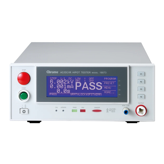
Controls and Indicators 1.3.1 Front Panel Controls and Indicators Figure 1-2 illustrates the controls and indicators on the front panel of the Sentry Plus Series AC/DC/IR Hipot Tester. Table 1-1 identifies them with description and function. STOP uadTech Sentry 30 Plus AC/DC/IR Hipot Tester... -
Page 23: Rear Panel Controls And Connectors
1.3.2 Rear Panel Controls and Connectors Figure 1-3 illustrates the controls and connectors on the rear panel of the Sentry Plus Series AC/DC/IR Hipot Tester. Table 1-2 identifies them with description and function. WARNING: FOR CONTINUED PROTECTION AGAINST FIRE HAZARD, REPLACE ONLY WITH... -
Page 24: Installation
Installation 1.4.1 Dimensions The Sentry Plus series unit is supplied in a bench configuration, i.e., in a cabinet with resilient feet for placement on a table. Flip feet are provided under the front feet so that the Sentry Plus instrument can be tilted up for convenient operator viewing. -
Page 25: Safety Inspection
Refer to paragraph 1.4.3 and Figure 1-5. The Sentry Plus instrument is shipped with a standard U.S. power cord, QuadTech P/N 4200- 0300 (with Belden SPH-386 socket or equivalent, and a 3-wire plug conforming to IEC 320). -
Page 27: Terms And Conventions
Section 2: Operation Terms and Conventions Table 2-1: Measurement Unit Prefixes Multiple Scientific Engineering Symbol 10 15 1000000000000000 Peta 10 12 1000000000000 Tera 10 9 1000000000 Giga 10 6 1000000 Mega 10 3 1000 Kilo 10 -3 .001 milli 10 -6 .000001 micro 10 -9... - Page 28 Dielectric Absorption: The physical phenomenon in which insulation appears to absorb and retain an electrical charge slowly over time. Apply a voltage to a capacitor for an extended period of time. Then quickly discharge it to zero voltage. Leave the capacitor open circuited for a period of time then connect a voltmeter to it and measure the residual voltage.
- Page 29 Insulation Resistance: Measures the total resistance between any two points separated by electrical insulation. The IR test determines how effective the dielectric (insulation) is in resisting the flow of electrical current. Interface: IEEE-488: General Purpose Interface Bus (GPIB). GPIB is an industry standard definition of a Parallel bus connection for the purpose of communicating data between devices.
- Page 30 Limits: High Limit: The upper value for a test to be considered a pass. If the measured value is higher than the high limit the test is considered a fail. In hipot, leakage current and ground bond test modes a high limit is required.
-
Page 31: Startup
Power is applied to the Sentry Plus Series instrument by pressing the green [POWER] switch on the front panel to the ON (1 position). The Sentry Plus Series unit should warm up for a period of at least 15 minutes prior to use. - Page 32 The function keys on the right hand side of the display allow the operator to access the numerous menus imbedded within the Sentry Plus Series instrument software. Familiarize yourself with these menus prior to programming a test. Figure 2-1 illustrates the STAND BY display and lists the functions that can be accessed by pressing the [F1] through [F4] keys.
- Page 33 POWER UP and STAND BY Displays The Sentry Plus Series instruments have multiple menus or displays that may seem confusing at first glance. In an attempt to clarify the numerous functions of the software, this instruction manual will illustrate these displays in a (hopefully) logical format. The function keys (F1, F2, F3 &...
- Page 34 PROGRAM Mode Displays Figure 2-4 illustrates each program mode display for quick reference. The box in the lower left hand corner denotes the instrument status. For clarity, a green arrow (!) is used to denote which function key (F1 – F4) is pressed to get to the next display screen. STEP 1/1 PROGRAM To enter programming mode.
-
Page 35: Programming A Ground Continuity Test
Programming a Ground Continuity Test This test is applicable to the Sentry 10, 20 and 30 Plus instruments. A Ground Continuity (GC) test is usually done first to verify the ground connection before high voltage is applied in the AC &... - Page 36 Programming a GC Test (continued): STEP 1/1 To set Dwell time: INC. 0.1 - 1s in 0.1s increments CURR: 0.1A DEC. HIGH: 1.2Ω DWELL DWELL: 0.3s NEXT Time To move highlighted box to LOW. EXIT 0.1 - 1s LOCK OFST STEP 1/1 To set Low resistance limit: INC.
-
Page 37: Programming An Ac Hipot Test
Programming an AC Hipot Test This test is applicable to the Sentry 10, 20 and 30 Plus instruments. With the instrument in ‘stand-by’ status, press [F1] = PROGRAM. If continuing the 5-step example from ¶2.4, you are already in program mode and on the AC test mode page. Follow the green arrows (!) on the right side of this diagram to program the individual AC hipot test parameters. - Page 38 Programming an AC Hipot Test (continued) STEP 2/2 3.00mA Set arc current limit: INC. 1-20mA in 0.1mA increments VOLT 2.750kV RAMP DEC. HIGH 15.00mA FALL Arc Limit TIME 10.0s NEXT To move highlighted box to RAMP. EXIT 1 - 20mA 0 = OFF LOCK OFST STEP 2/2...
-
Page 39: Programming A Dc Hipot Test
Programming a DC Hipot Test This test is applicable to the Sentry 20 and 30 Plus instruments. With the instrument in ‘stand- by’ status, press [F1] = PROGRAM. If continuing the 5-step example from ¶2.5, you are already in program mode and on the AC test mode page. The example illustrated herein shows a GC test as Step 1, an AC test as Step 2 and how to program a DC test in Step 3. - Page 40 Programming an DC Hipot Test (Continued) STEP 3/3 0.015mA Set arc current limit: INC. 1-5mA in 0.1mA increments VOLT 2.500kV RAMP DEC. HIGH 2.999mA DWELL Arc Limit TIME 5.0s FALL NEXT To move highlighted box to RAMP. I-RUS EXIT 1 - 5mA 0 = OFF LOCK OFST STEP 3/3...
-
Page 41: Programming An Insulation Resistance (Ir) Test
NOTE: In-Rush Current The In-Rush current limit for the DC hipot test is a low limit which is monitored during initial charging of the device under test. When activated (other than Off), current below the programmed value is considered to be a Fail condition. - Page 42 Programming an IR (Insulation Resistance) Test (Continued) To set high resistance limit: STEP 4/4 HIGH INC. 0 - 50GΩ in 0.1MΩ increments RAMP (from programmed low limit to 50G Ω) VOLT 0.750kV DWELL DEC. High 1.5MΩ FALL Resistance TIME 5.0s NEXT To move highlighted box to RAMP.
-
Page 43: Programming A Pause (Pa) In Test Sequence
Programming a Pause in Test Sequence “PAUSE” is a mode selection that allows a test sequence to be stopped while test leads are changed or other operations performed. A 15-character user programmable message will be displayed on the screen when in PAUSE mode and the test will continue when the [START] button is pressed or when START is initiated via remote I/O. - Page 44 Programming a PAUSE in test sequence (continued): STEP 5/5 To set test signal: INC. OFF or ON PAUSE CHANGE-DUT DEC. UNDER TEST SIGNAL Test Signal NEXT To move highlighted box to STEP. EXIT OFF / ON LOCK OFST STEP INC. To set next test step PAUSE CHANGE-DUT...
-
Page 45: Storing A Test Setup
Storing a Test Setup NOTE: Instrument PRESET values can be programmed and stored for your specific test setup. Therefore before storing your tests, program the preset values. Refer to p 2.11 for PRESET programming information. To store the previous example of the programmed 5-step test, with the instrument in ‘STAND BY’... - Page 46 To label the selected location, press [F1] = UP (and/or [F2] = DOWN) to enter a combination alpha-numeric name for this test setup. Press [F3] = NEXT C. after each digit to accept that digit and move on to the next. The name can be up to 10 characters long. When finished entering the name, press [F3] = ENTER two times.
-
Page 47: Programming A Multi-Step Test
Paragraphs 2.4, 2.5, 2.6, 2.7 and 2.8 illustrate the programming of a 5-step test (GC, AC, DC, IR & PA). To program a multiple step test, power-up the Sentry Plus Series instrument so the ‘Stand By’ display is shown (Figure 2-2). -
Page 48: Preset Test Parameters
PRESET values. It is important to set the PRESET values prior to storing a test program. Table 2-3 lists the Sentry Plus Series PRESET test parameters including parameter range and initial (default) value. Table 2-3: PRESET Test Parameters... -
Page 49: Ir Auto Range
2.11.4 IR AUTO RANGE The IR Auto Range setting allows the option of using the full scale current range (ON) or using the user programmed maximum current limit (OFF). To increase measurement resolution in IR mode, select IR Auto Range ON. To increase measurement speed in IR mode, select IR Auto Range OFF. -
Page 50: Instrument Offset
DUT attached. For maximum measurement accuracy it is recommended that the OFFSET function be performed on the Sentry Plus Series instrument after power up, any time the test parameters are changed and any time the test leads or fixture is changed. Return and HV test leads should not be connected together (open circuit) for AC and DC hipot tests. - Page 51 OFFSET Function There is no offset in the IR or PA modes. Using the pre-programmed example from paragraphs 2.4-2.8 of the GC, AC, DC, IR & PA 5-step test the resultant error and correction is illustrated herein. STEP 1/5 0.3Ω PROGRAM 0.1A "STAND BY"...
- Page 52 Offset (continued) To turn to Offset function OFF, and return to STAND BY status, follow the screens herein. 0.3Ω PROGRAM 0.1A PRESET 5-Steps Programmed 1.2Ω [F4] Offset ON Ready to Test MENU 0.5s MORE.. STAND BY LOCK OFST OUTPUT MEASURE RESULT 0.1A 1.2Ω...
-
Page 53: Connection To Device Under Test
2.13 Connection to Device under Test Figure 2-5 illustrates the connection of the Sentry Plus Series unit to a single DUT using the S02 1-meter HV cable set that comes standard with the instrument. The custom white banana plug/red alligator clip is connected between the OUTPUT terminal on the Sentry Plus Series unit and the high side of the device under test. -
Page 54: Measurement Procedure
Press [STOP] at any time to terminate the output voltage and stop the test. The Sentry Plus Series instrument judges the measurement value as GOOD or NO GOOD. A GOOD judgment means the DUT passed all programmed steps. Upon completion of the test the output voltage is terminated and the display shows PASS. - Page 55 Error Messages (FAIL result) When the measurement value was judged NO GOOD and FAIL is shown on the display, an error message denoting the test result will be shown on the display also. Table 2-4 lists the possible error messages for a NO GOOD/FAIL judgment. Table 2-4: Error Messages Error Message Description...
-
Page 56: Menu Parameters
2.15 MENU Parameters With the Sentry Plus Series instrument in STAND BY status, press [F3] = MENU to access programmable instrument parameters. The MENU display contains the Memory, System, Option, Calibration, Key Lock, Change Password, Error Log and About functions. Table 2-5 lists these functions with description and default values. -
Page 57: Memory Function
2.15.1 MEMORY Within the MEMORY function is the ability to STORE, RECALL or DELETE test setups, preset parameters and offset values. There are 60 memory locations available and a single location may contain 1-10 steps. The total memory array is 60 and the instrument uses up to 10 locations to run the test(s). - Page 58 To Recall a Test Setup: With the Sentry Plus instrument in Stand By status: Press [F3] = MENU. Press [F3] = SELECT to select MEMORY from the menu parameters list. Press [F2] = RECALL to select the recall function. Press [F1] = LAST or [F2] = DOWN to toggle through the test steps. When the highlighted box is around the test step you want (3.
-
Page 59: System Function
The EN50191 function sets the maximum leakage current at 3mA AC or 5mA DC in accordance with the European standard. When EN50191 is ON, the Sentry Plus Series instrument will terminate the voltage at the output terminals when the leakage current exceeds 3mA AC or 5mA DC. -
Page 60: Dc 50V Agc
The CALIBRATION function requires a password to enter the instrument routine. Only qualified service personnel with NIST traceable standards should perform instrument calibration. Refer to paragraph 4.3 for the full Sentry Plus Series calibration procedure. Page 60 of 85 Operation... -
Page 61: Key Lock Function
2.15.5 KEY LOCK To lock out the PROGRAM, PRESET and MENU functions of the Sentry Plus Series instrument use the KEY LOCK function in the MENU parameters. The initial instrument setting is OFF. To activate the KEY LOCK function with the instrument in STAND BY status: •... - Page 62 KEY LOCK (continued) • Display prompts ‘RECALL LOCK?’ • NOTE: This means: “Do you want to lock out the ability to recall memory locations?” • Press [F1] = YES to select KEY LOCK ON. • NOTE: Selecting YES disallows the recalling of programmed tests from memory. •...
-
Page 63: Change Password Function
2.15.6 CHANGE PASSWORD The Sentry Plus Series instruments have a password function for locking out the front panel so that the instrument PRESET settings and PROGRAM function are disabled. The CHANGE PASSWORD function applies to the initial instrument password. The password is comprised of “A”... - Page 64 • Display prompts ‘NEW PASSWORD’ • Press [B] [B] [B] [B] [ENTER] • Display prompts ‘CONFIRM’ • Press [B] [B] [B] [B] [ENTER] • Display prompts ‘CHANGE PASSWORD OK’. Press F1 = "A" to input password CHANGE PASSWORD character Press F2 = "B" to input password xxxx NEW PASSWORD character...
-
Page 65: Error Log Function
2.15.7 ERROR LOG The Sentry Plus Series instruments have an Error Log to track invalid remote commands. The remote interface is not available at this time. 2.15.8 ABOUT The Sentry Plus Series instruments have a parameter labeled ‘About’. This parameter lists the instrument manufacturer, software version and date. -
Page 67: Remote
Section 3: Interface Remote A 9-pin D-Series remote control connector is located on the rear panel of the Sentry Plus Series instrument. There is a black 5 screw terminal strip for the remote input signals: START, RESET, COM and INTERLOCK. Inputs require a contact closure. Figure 3-1 illustrates the Remote terminal strip connector and 9-pin D-Series connector. - Page 68 Figures 3-2 and 3-3 illustrate possible remote control connections to the Sentry Plus Series terminal strip. Use extreme care when using a remote control connection as the High Voltage Output is being turned ON and OFF with an external signal.
- Page 69 Figure 3-5 illustrates the timing diagram for the Sentry Plus Series instruments under a PASS condition and a FAIL condition. PASS CONDITION FAIL CONDITION CLOSE START OPEN CLOSE UNDER TEST OPEN 180ms 180ms CLOSE PASS OPEN 0.5ms CLOSE FAIL OPEN 0.5ms...
-
Page 70: G16 International Power Strip
G16 International Power Strip The Sentry Plus Series instruments can be connected to the G16 International Power Strip as illustrated in Figure 3-6 for safety testing of many European corded products. *Australia *United Kingdom *Denmark *North America *Norway *Finland *Sweden... -
Page 71: S07 Power Entry Adapter Cable
The S07 Power Entry Adapter Cable is a 3-wire AC inlet receptacle for precise testing of corded products. The S07 cable is connected to the Sentry Plus Series instrument via a two-lead set. 1. Remove DUT’s power cord form its AC inlet module. -
Page 72: S03 Corded Product Adapter
The S03 Corded Product Adapter is a 3-prong electrical outlet box to facilitate testing of corded products. The S03 cable is connected to the Sentry Plus Series instrument via a two-lead set. 1. Connect the black banana plug to the Sentry Plus RTN/LOW. -
Page 73: S05 Foot Switch
S05 Foot Switch The S05 Foot Switch provides hands-free remote testing capability. The spade leads on the S05 Foot Switch are connected (screwed) to the terminal strip on the rear panel of the Sentry Plus Series instrument. 1. Connect (screw) the white wire/spade connector to the START terminal. 2. -
Page 74: S08 Gun Probe
S08 Gun Probe The S08 Gun Probe provides fast testing capability with pinpoint control. Use the black lead of the S02 Lead Set with the S08 Gun Probe. 1. Connect the S02 black banana plug to the Sentry Plus RTN/LOW terminal. 2. -
Page 75: S50 Plus Ground Bond Tester
1A to 30A AC in 0.01A increments and resistance can be measured over the range 0.1mΩ to 510mΩ. The rear panels of the Sentry Plus Series instrument and Sentry 50 Plus instrument are connected via the S15 9-pin interconnection cable. Figure 3-11 illustrates the front panel connections of the two instruments. -
Page 77: General
Attention: RMA# Shipments sent collect cannot be accepted. Calibration Calibration of the Sentry Plus Series instruments is recommended on an annual basis. If the unit is returned to QuadTech for factory calibration, refer to paragraph 4.2 for RMA and shipping instructions. -
Page 78: Calibration Parameters
500kΩ Resistance Standard 4.3.1 Calibration Parameters Table 4-2 contains the calibration parameters for the Sentry Plus Series instruments. All tests points are not required for each of the instruments (10 Plus, 20 Plus & 30 Plus). Table 4-2: Calibration Parameters... -
Page 79: Enable Calibration
The instrument should be powered up for a minimum of 30 minutes prior to calibration to ensure maximum stability. With the Sentry Plus Series instrument in standby status ([STOP] button previously pressed and no warning lights flashing) remove the Calibration seal over the hole labeled “CAL’... -
Page 80: Ac Voltage Calibration
4.3.3 AC Voltage Calibration Connect the OUTPUT terminal of the Sentry Plus Series unit to the input terminal of the AC/DC high voltage meter. Connect the RTN/LOW terminal of the Sentry Plus to the GND terminal of the voltmeter. Set the voltmeter to AC and 2kV range. -
Page 81: Ir Voltage Calibration
4.3.5 IR Voltage Calibration (IRV) Keep the setting on the Valhalla voltmeter at DC and 2kV range. IR calibration is applicable to the Sentry 30 Plus instrument. Press [F1] = UP to go to Cal Step 5: ‘IRV 1kV Offset (50V)’. -
Page 82: Ac Current Calibration
4.3.6 AC Current Calibration (ACA) Connect the OUTPUT terminal of the Sentry Plus Series instrument to a resistance box or resistance standard. Connect an AC/DC current meter in series between the resistance load (box/standard) and the RTN/LOW terminal of the Sentry Plus instrument. Table 4-3 lists the resistance loads necessary for the current calibration steps. -
Page 83: Dc Current Calibration
4.3.7 DC Current Calibration Connect the OUTPUT terminal of the Sentry Plus Series instrument to a resistance box or resistance standard. Connect an AC/DC current meter in series between the resistance load (box/standard) and the RTN/LOW terminal of the Sentry Plus instrument. -
Page 84: Arc Calibration
4.3.8 ARC Calibration ARC calibration is part of the calibration routine but it is not performed on the Sentry Plus instruments. ARC Calibration is set at the factory. To by-pass these two steps: Press [F1] = UP to go to Cal Step 15: ‘AC ARC 15mA (7mA)’. BY-PASS Press [F1] = UP to go to Cal Step 16: ‘DC ARC 5mA (5mA)’. -
Page 85: Ground Continuity Calibration
4.3.10 Ground Continuity Calibration GC 5Ω Ω Ω Ω Offset (1Ω Ω Ω Ω ) Connect a 1Ω load resistor between the Sentry Plus instrument’s rear panel RTN/LOW terminal and Ground Continuity Option terminal. Press [F1] = UP to go to Cal Step 21: ‘GC 5Ω...
Need help?
Do you have a question about the Sentry Plus Series and is the answer not in the manual?
Questions and answers