Table of Contents
Advertisement
Quick Links
The material in this manual is for informational purposes only and is subject to change, without
notice. QuadTech assumes no responsibility for any error or for consequential damages that may
result from the misinterpretation of any procedures in this publication.
Potentially dangerous voltages may be present on front and rear panel terminals. Follow all
warnings in this manual when operating or servicing this instrument. Dangerous energy levels
may be stored in capacitors tested by this unit. Always make sure the high voltage indicator is
not on when connecting or disconnecting the unknown.
!
Product will be marked with this symbol (ISO#3684) when it is necessary for the user to
refer to the instruction manual in order to prevent injury or equipment damage.
Product marked with this symbol (IEC417) indicates presence of direct current.
Product will be marked with this symbol (ISO#3684) when voltages in excess of 1000V
are present.
1865 Megohmmeter/IR Tester
©QuadTech, Inc., 1992
5 Clock Tower Place, 210 East
Maynard, Massachusetts, U.S.A. 01754
October, 2006
Telephone
978-461-2100
Sales
800-253-1230
Facsimile
978-461-4295
Website
www.quadtech.com
WARNING
Instruction Manual
Form
150073/D5
Advertisement
Table of Contents

Subscribe to Our Youtube Channel
Related Manuals for QuadTech 1865


Summary of Contents for QuadTech 1865
- Page 1 The material in this manual is for informational purposes only and is subject to change, without notice. QuadTech assumes no responsibility for any error or for consequential damages that may result from the misinterpretation of any procedures in this publication.
- Page 2 Page 2 of 87...
-
Page 3: Table Of Contents
Contents Warranty ......................7 Specifications ......................9 Accessories ......................11 Safety Precautions ....................13 Condensed Operating Instructions ................15 Introduction - Section 1 Unpacking and Inspection ................21 Product Overview ..................21 Controls and Indicators..................22 1.3.1 Front Panel Controls and Indicators ..........22 1.3.2 Rear Panel Controls and Connectors ..........24 Installation .....................25 1.4.1 Dimensions ..................25 1.4.2 Instrument Positioning ...............25... - Page 4 Contents (Continued) Operation - Section 2 (Continued) 2.6.3 I/O Menu....................45 2.6.3.1 Display Type.................45 2.6.3.2 Result Format................46 2.6.3.3 RS-232 ..................47 2.6.3.4 IEEE-488................48 2.6.3.5 Handler..................48 2.6.3.6 Results to Floppy ..............48 2.6.4 Utilities Menu ..................50 2.6.4.1 Save Setup................51 2.6.4.2 Recall Setup ................53 2.6.4.3 Zero ..................54 2.6.4.4 Lock Out ................55 2.6.4.5 Calibration ................55 2.6.4.6 Set Time/Date ...............56...
- Page 5 Contents (Continued) Theory Section 4 General......................79 Instrument Description ..................79 4.2.1 Basic I2000 Instrument Architecture..........79 4.2.2 1865 Instrument Modules ..............80 4.2.3 I2000 Instrument Options ..............81 Maintenance/Calibration - Section 5 General......................83 Instrument Return ..................83 Routine Maintenance ..................83 5.3.1 Battery Replacement................84 5.3.2 Resetting of Time and Date ...............85 5.3.3 Loss of Display Contrast..............85...
- Page 6 Page 6 of 87...
-
Page 7: Warranty
QuadTech's applicable published specifications. If within one (1) year after original shipment it is found not to meet this standard, it will be repaired, or at the option of QuadTech, replaced at no charge when returned to a QuadTech service facility. - Page 8 Page 8 of 87...
-
Page 9: Specifications
Specifications 1 x10 3 to > 1x10 14 Ω(dependent on test voltage) Resistance Range: 1x10 6 - >1x10 14 Ω at 1000VDC 1x10 5 - 1x10 13 Ω at 100VDC 1x10 4 - 1x10 12 Ω at 10VDC 1x10 3 - 1x10 11 Ω at 1VDC (7 ranges or auto ranging) Resistance Accuracy:* ±[0.45% +{(Rx/Vx)(0.0005 FS + 2pA) + 30Ω/Rx}100%] Rx: Measured resistance in ohms... - Page 10 I/O Port (w/safety interlock) Optional -1865-01 - IEEE-488, factory installed at unit purchase 1865-02 - Floppy Drive, 3.5", factory installed only 1865-03 - Rear panel input terminals, factory installed at purchase 1865-70 - IEEE-488, field retrofit Input Terminals: Four sheathed banana plugs, front or rear mount (optional)
-
Page 11: Accessories
Accessories Accessories Included Item Quantity QuadTech P/N U.S. AC Power Cable (3-prong) 4200-0300 T2.5A 250V 5X20mm Line Fuse 520049 1MΩ Capacitor Adaptor 800015 100kΩ Capacitor Adaptor 800014 Interlock Connector 630019 Instruction Manual 150073 Calibration Certificate Accessories/Options Available Item Quantity QuadTech P/N... - Page 12 Page 12 of 87...
-
Page 13: Safety Precautions
CAUTION HIGH VOLTAGE LED is lit. Before turning on the 1865 unit, make sure the AC power cord is plugged into the proper voltage source and that there is no device (DUT) or fixture connected to the test leads. - Page 14 Page 14 of 87...
-
Page 15: Condensed Operating Instructions
The 1865 can be operated from a power source between 90V and 250V AC at a power line frequency of 47 to 63 Hz. The standard 1865 is shipped from the factory with a 2.5A fuse in place for 115V or 220V operation. To change the fuse refer to paragraph 1.4.3. - Page 16 Before measuring, zero out test lead or fixture measurement errors as follows. 1. If test leads are to be used connect them to the 1865 input terminals, red to + unknown, black to - unknown, with probes open and spaced some distance apart (or fixture open).
- Page 17 (those at power up), set using menus or the operator can recall a previously stored setup. 1. Connect the device under test to the 1865 test leads or other fixture being used. 2. Press [MENU] key to select menu display.
- Page 18 Condensed Operating Instructions Saving Setups 1. To save the current set of test conditions as entered (conditions include, voltage, test times, measurement range, limit, and display modes): Press [MENU] key to select menu display. Press Right or Left Arrow key to select Utilities menu. Press Up or Down Arrow key to select Save Setup.
- Page 19 Condensed Operating Instructions Setting Pass/Fail Limit 1. To enter a single measurement limit for resistance or current (depending on results display selected): Press [MENU] key to select menu display. Press Right or Left Arrow to select Setup menu. Press Up or Down Arrow key to select Limit in sub menu. Press [ENTER] key to activate the limit entry field.
-
Page 21: Unpacking And Inspection
Section 1: Introduction WARNING High voltage is applied to the measurement terminals of the 1865 anytime the CAUTION HIGH VOLTAGE LED is ON. While the current from the instrument is limited to a value that is not dangerous under most conditions, the energy stored in a capacitor connected to the terminals may be lethal. Always make sure the CAUTION HIGH VOLTAGE LED is OFF when connecting or disconnecting the unknown. -
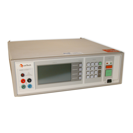
Page 22: Controls And Indicators
Controls and Indicators 1.3.1 Front Panel Controls and Indicators Figure 1-1 shows the controls and indicators on the front of the 1865 unit. Table 1-1 identifies them with description and function. 12 11 10 QuadTech DISPLAY SELECT ENTRY TEST Megohmmeter... - Page 23 Table 1-1: Front Panel Controls and Indicators (Continued) Reference Name Type Function Number Figure 1-1 MENU Green Push Button Press to enter menu display mode or press to exit sub menu & return to main menu. CNCL Gray Push Button To exit menu mode with no parameter changes made or to exit current field ENTER...
-
Page 24: Rear Panel Controls And Connectors
1.3.2 Rear Panel Controls and Connectors Figure 1-2 illustrates the controls and connectors on the rear panel of the 1865 Megohmmeter/IR Tester. Table 1-2 identifies them with description and function. NO USER SERVICEABLE PARTS CAUTION: FOR CONTINUED INSIDE PROTECTION AGAINST FIRE... -
Page 25: Installation
115V or 220V source. Always use an outlet which has a properly connected protection ground. The standard 1865 is factory shipped with the 2.5A fuse in place. The instrument can be damaged if the wrong fuse is installed. To change the fuse... - Page 26 RS-232 INTERFACE 90 - 250 V 47 - 63 Hz 40 WATTS MAX Figure 1-4: 1865 Instrument Fuse Drawer • Remove the fuse drawer by inserting a small flat head screwdriver behind the small tab to force the draw outward.
-
Page 27: Safety Inspection
1.4.4 Safety Inspection Before operating the instrument inspect the AC power inlet module on the rear of the 1865 instrument to ensure that the properly rated fuse is in place, otherwise damage to unit is possible. Refer to paragraph 1.4.3. -
Page 29: Terms And Conventions
Section 2 : Operation Terms and Conventions The names of keys in the manual will generally appear in CAPITAL LETTERS. The MENU key calls up the main menu display and returns to the line previously selected. The ">>" symbol on a menu indicates a lower level menu exists. The select keys generally function as UP, DOWN, LEFT and RIGHT arrow and allow you to move through a menu or field of choices to make the desired selection or turn a function ON or OFF. -
Page 30: Zeroing
Power is applied to the 1865 by pressing the [POWER] button on the front panel. The instrument runs a self test and any error messages are displayed accordingly (refer to paragraph 2.8). Zeroing Before making measurements, the 1865 instrument should be zeroed to correct for test lead or fixture errors. - Page 31 Figure 2-2 illustrates the two-wire connection to DUT. The two-wire ungrounded connection is the recommended connection of ungrounded components or components that can be connected very close to the 1865 input terminals rather than through the lead set provided. High...
-
Page 32: Measurement Procedure
This is the preferred measurement mode, especially when the approximate resistance value is unknown, since the 1865 instrument employs an auto ranging technique. The automatic mode would generally be used in a production environment where measurements are repetitive and setup conditions have been previously established. -
Page 33: Default Measurement Conditions
Whenever the 1865 unit is powered up it is ready to begin measuring at default test conditions. Initially, these conditions will be set to a factory default (1V, 0 times, Resistance Display, Auto ranging and Automatic Mode), but can be changed by the user and stored to overwrite factory default. -
Page 34: Automatic Measurement Mode
2.5.3 Automatic Measurement Mode Measurements in the automatic mode can be initiated after connecting the DUT by simply pressing [START]. Test conditions are determined by either the power up default conditions or recalling a previously stored setup from instrument memory. In either case a test cycle is sequenced automatically (Figure 2-5) once [START] is pressed and results displayed (Figure 2-6). - Page 35 Measurement Value Measurement Parameter Measurement Units (Resistance or Current) (Engineering or Scientific) RESISTANCE Test Cycle Status 1.000M (Charge, Dwell, Measure or Discharge) MEASURE VOLTAGE = 1000 LIMIT = 9.0 e +005 Pass/Fail Limit Charge MODE = AUTO RANGE = 10 uA (A) Voltage REMOTE Measure Mode...
-
Page 36: Manual Measurement Mode
Menu Functions 2.6.1 General All programmable functions of the 1865 are controlled by easy to use menu displays. The user enters the menu mode by selecting the [MENU] key which calls up three top level menus, Setup, I/O and Utilities. Each one of these is comprised of a sub menu list whose functions are described in detail below. -
Page 37: Setup Menu
1000 volts. This is the voltage applied to the unit under test during the test cycle and present at the DUT connection anytime that the CAUTION HIGH VOLTAGE lamp is ON. As in the case of many of the menu entries on the 1865 instrument, an "error message" will be displayed for an invalid entry. -
Page 38: Charge Time
2.6.2.2 Charge Time Setup Utilities Voltage = 1000 Charge Time Dwell Time = 10 Measure Time = 10 Discharge Time = 10 Mode Auto Manual Range > > Limit = 100 e+ 9 Stop on Pass to Average Figure 2-11: Charge Time Entry Accepts entry of a charge time between 0 and 300 seconds in 1 second intervals (up to 3 digits). -
Page 39: Discharge Time
2.6.2.5 Discharge Time Accepts entry of a discharge time between 0 and 300 seconds in 1 second intervals. This is the time when the test voltage is removed and the device under test discharged. The CAUTION HIGH VOLTAGE lamp goes OFF at the end of the programmed interval and the last measurement result is retained on the display (unless no display is selected). -
Page 40: Range
Through a lower level menu (by pressing [ENTER]) allows for selection of Auto or one of seven different measurement ranges (1mA through 1nA), which is the maximum current for the selected range. In auto mode the 1865 instrument will automatically select the optimum range depending on the programmed test voltage and current drawn by the test device. - Page 41 0.5uA ( I = 100V/200MΩ). Based on the above one would expect the 1865 instrument to auto range from the 1mA to 1uA range (50% of maximum current) or the user to select the 1uA range if prior knowledge of the expected results is known.
- Page 42 Measurement Ranges at Specified Voltage 1 mA 100 uA 10 uA 1 uA 100 nA 10 nA 1 nA 1000 1.00E+ 03 1.00E+ 04 1.00E+ 05 1.00E+ 06 1.00E+ 07 1.00E+ 08 1.00E+ 09 1.00E+ 10 1.00E+ 11 1.00E+ 12 1.00E+ 13 1.00E+ 14 1kΩ...
-
Page 43: Limit
Pass/Fail indicator and Pass/Fail display, when enabled. When the 1865 instrument is in the resistance mode the limit is a minimum value i.e. any value above the limit will result in a Pass, whereas a value below the limit will result in a Fail. -
Page 44: Stop On Pass
2.6.2.9 Stop on Pass Accepts entry of a value between 0 and 300 which is the number of consecutive passing measurements that must occur to exit the measure loop before the measure time has passed. This is only active when there is a measure time and limit specified. An entry of 0 disables the stop on pass function. -
Page 45: I/O Menu
Current, Pass/Fail or No Display. In resistance mode the 1865 instrument will display the measured value of resistance of the device under test. In current mode the 1865 displays the current to the device under test. In Pass/Fail mode the actual measured value is displayed in small font along with a pass or fail based on the measurement limit entered, which could apply to either resistance or current. -
Page 46: Result Format
In No Display only the voltage, mode and range are displayed, with no measured value. This might be used for security reasons or for the purpose of reducing test time during remote operation. When the display is selected as current one needs to keep in mind that the 5kΩ input impedance and the 1kΩ... -
Page 47: Rs-232
A summary of measurement units (scientific and engineering) and their symbols is given in Table 2-2. Table 2-2: Measurement Unit Prefixes Multiple Scientific Engineering Symbol 10 15 1000000000000000 Peta 10 12 1000000000000 Tera 10 9 1000000000 Giga 10 6 1000000 Mega 10 3 1000... -
Page 48: Ieee-488
2.6.3.4 IEEE-488 Utilities Setup IEEE Address Mode Talk Talk/Listen State Disable Enable Figure 2-20: IEEE-488 Interface Setup Allows user setup of IEEE-488 interface operation. Selections include: Address: 1 through 16 Mode: Talk or Talk/Listen State: Disable or Enable The instrument will function as either a Talk or a Talk/Listen device in a system depending on the choice made by the operator under Mode. - Page 49 When multiple tests are being conducted the results are stored to floppy periodically (every 10 measurements) from an internal buffer. To be sure of storing all results before power is shut down the file needs to be closed as discussed earlier. It is also important to note that a file should be closed before changing or recalling a new set of test conditions, otherwise the stored measurement results would not be consistent with the setup conditions stored in the file.
-
Page 50: Utilities Menu
1.020 M ohm PASS 1.020 M ohm PASS 1.020 M ohm PASS 1.020 M ohm PASS 1.020 M ohm PASS 1.020 M ohm PASS 1.020015E+006 PASS 1.020015E+006 PASS 1.020015E+006 PASS 1.020015E+006 PASS 1.020015E+006 PASS The number of measurement results that can be stored is dependent on available disk space and length of the data string. -
Page 51: Save Setup
2.6.4.1 Save Setup Setup Utilities Save DEFAULT FLOPPY 1865-1 1865-2 1865-3 1865-4 page down Figure 2-22: Save Setup Test Conditions Allows a set of test conditions to be stored in instrument memory or on floppy disk (if optional drive is installed) for later recall. Test conditions are those that are user programmable in the Setup and I/O menus, refer to paragraphs 2.6.2 and 2.6.3 above. - Page 52 Yes to overwrite and the other way is to enter the same name under New and answer Yes to overwrite. Setup Utilities Save 1865-100 1865-102 1865-103 1865-104 Cable-2 Cap-1...
-
Page 53: Recall Setup
It is possible to store about 25 sets of test conditions in unit memory and many more can be stored on 3 1/2" disks when the 1865 includes the floppy drive option. NOTE 3 1/2" floppy disks must be formatted for DOS compatibility on a PC or purchased formatted from the manufacturer, 1.44M high density or 720K low density. -
Page 54: Zero
When there are more setups than can fit on the display the page down key is active. If there is less than a whole page below, the display wraps around to the previous display. Continuing to page down will eventually return to the first display of setups. NOTE Setups saved using version 1.6 (or earlier) operating software can not be recalled with software 2.0 or later. -
Page 55: Lock Out
2.6.4.4 Lock Out Allows user to turn keypad lock feature ON or OFF. There are two choices which can be selected, lockout only and lockout with setup recall . In both modes only the [START], [STOP] and [MENU] on the instrument front panel are active, all other keys disabled. The difference is that in lockout with setup recall the menu key also allows setups to be recalled from instrument memory. -
Page 56: Set Time/Date
2.6.4.6 Set Time/Date Tue Jan 14 10: 37: 10 1992 TO CHANGE TIME PRESS T KEY TO CHANGE DATE PRESS D KEY TO RETURN PRESS <MENU> Figure 2-28: Set Current Date and Time Allows resetting of time and date into unit memory. This is used as the basis for the elapsed time counter and stored calibration date. -
Page 57: Elapsed Time
2.6.4.7 Elapsed Time When selected, indicates the total elapsed time in hours that the unit has been powered up. This is from the moment of initial use and will show some time when shipped from the factory. THE TOTAL OPERATING TIME FOR THIS INSTRUMENT IS 1205.50 hours HIT<MENU>... -
Page 58: Set Contrast
Input/Output Interface 2.7.1 I/O Interface The 1865 instrument comes standard with an I/O interface port available through a connector (36 pin) on the rear panel of the instrument. This is generally used for interfacing to an automatic component handler. Refer to Table 2-3 for signal names, pin numbers and functions as necessary for cable connections. - Page 59 INTERLOCK Operator Safety feature primarily for use with external fixtures (i.e. operation of the 1865 instrument can be disabled until the cover of the fixture is closed). To enable the interlock function, pin 31 must be connected to ground or controlled electrically with a logic low.
-
Page 60: Ieee-488 Interface
Figure 2-33: Isolated Connection 2.7.2 IEEE-488 Interface The IEEE-488 interface is available as an option to the 1865. When this option is present connection is made through a connector (24 pin) on the rear panel. This interface can be used to connect to a system containing a number of instruments and a controller in which each meets IEEE Standard 488.2-1987 (Standard Digital Interface for Programmable... - Page 61 Table 2-4: IEEE-488 Interface Connections Signal Name Pin Number Function Low state: "Data is Available" and valid on DI01 through DI08 NRFD Low state: At least one listener on the bus is "Not ready for Data". NDAC Low state: At least one listener on the bus is "Not Accepting Data".
- Page 62 Table 2-5: IEEE and RS-232 Commands Command Function Parameter(s) CONFigure: VALid? Is filename valid to save? xxxxxxxx SAVe: DUPLicate Save setup as duplicate filename in battery backed up RAM xxxxxxxx Save setup as new filename in battery backed up RAM xxxxxxxx RECall filename Recall setup filename from battery...
- Page 63 (-) when the parameter is selected as current. Pass can also be Fail or neither if no limit is entered. IDN? Returns instrument identification "QuadTech,1865,0,software version" START Initiates a measurement in Auto mode, in Manual mode it initiates charge, if sent again it takes one measurement, each time sent thereafter one additional measurement is taken.
- Page 64 Table 2-5: IEEE and RS-232 Commands (Continued) * Note Description of the 21 values returned by the remote “CAL: DATA?” The value of the internal voltage standard The 100 volt full scale value The 1000 volt full scale value The gain of the 500:1 voltage attenuator (.002) The gain of the 50:1 voltage attenuator (.02) The gain of the 5:1 voltage attenuator (.2) The input resistance...
-
Page 65: Sample Program For National Instruments Gpib Card
CLS '***************** MEASURE AND DISPLAY DATA******************* 'get the identification of the unit SET$ = "IDN?" '1865 setup string CALL IBWRT(qt1865%, SET$) 'send string to 1865 c$ = SPACE$(25) CALL IBRD(qt1865%, c$) 'get data PRINT "unit ID is "; c$ 'print result SET$ = "CONF:VOLT 100"... -
Page 66: Sample Program For Io Tech Gpib Card
2.7.4 Sample Program for IO Tech GPIB card OPEN "\dev\ieeeout" FOR OUTPUT AS #1 IOCTL #1, "BREAK" PRINT #1, "RESET" OPEN "\dev\ieeein" FOR INPUT AS #2 PRINT #1, "fill error" PRINT #1, "remote 04" PRINT #1, "local lockout" id$ = space$(30) : c$=space$(15) PRINT #1, "output 04;idn?"... -
Page 67: Rs232 Interface
PRINT #1, "local" 2.7.5 RS232 Interface The 1865 instrument comes standard with an RS232 serial port interface, available through a connector (9 pin) on the rear panel of the instrument, for connecting to a PC. The RS232 standard defines electrical specifications for the transmission of bit serial information. -
Page 68: Sample Program For Rs232
Cable Configuration 1865 Controller Pin # Function Pin # Function Receive data Connect Transmit data Transmit data Receive data Data terminal ready Data set ready Signal ground Signal ground Data set ready Data terminal ready db9 to db25 Cable Configuration... -
Page 69: Results To Printer
LOOP RETURN 2.7.7 Results to Printer The 1865 can be setup to output to an RS-232 or IEEE printer. Results format is the same as results to floppy, refer to paragraph 2.6.3.6. RS-232 RS-232 must be selected on I/O Menus and format set IEEE must also be selected for Talk mode and Disable state. -
Page 70: Error Messages
2.8 Error Messages "BAD DRIVE-REQUEST STRUCTURE" Floppy option not present, defective or disk not inserted "BAD VOLTAGE SENT TO FUNCTION" Improper voltage entered during calibration procedure "BAD ZERO CALIBRATION" Zeroing error, repeat and/or remove component from input terminals/fixture (Refer to Note on p.63) "CALIBRATION STANDARD OUT OF Entered value >... - Page 71 "FLOPPY SEEK ERROR" Floppy option not present, defective or disk not inserted "FLOPPY WRITE FAULT" Floppy option not present, defective or disk not inserted "GENERAL FAILURE, FLOPPY" Floppy option not present, defective or disk not inserted "HANDLER PORT FAILURE" I/O port malfunction during power up "HARDWARE TIMER FAILURE, REBOOT"...
- Page 72 "PASSWORD NOT SAVED IN RAM" Error trying to save password, repeat "PASSWORD VERIFICATION FAILURE" Wrong password entry for verification "RANGE RESISTOR VALUE OUT OF RANGE" Malfunction of internal calibration resistors "REMOTE COMMAND INVALID" IEEE or RS232 command is incorrect (for example: to set voltage use VOLTage) "REMOTE COMMAND PARAMETER IEEE or RS232 parameter is incorrect (for...
-
Page 73: Insulation Resistance Testing
Section 3 : Applications Insulation Resistance Testing Insulation resistance of materials is one of several parameters that may indicate the condition of insulation. An insulation test is to measure the resistance offered by the insulating members of a component part to an impressed direct voltage tending to produce a leakage of current through or on the surface of these members. -
Page 74: Test Sample Resistivity Measurements
Test Sample Resistivity Measurements The 1865 can be used for measuring the resistivity of test samples as described by ASTM Standard D 257, which describes in detail the techniques for both surface and volume resistivity measurements. The 1865-11 Test Cell is shown in Figure 3-1... -
Page 75: Capacitor Insulation Resistance
When this is amplified by the current amplifier of the measuring instrument results can fluctuate and vary widely. To eliminate this in the 1865 two resistance adapters are supplied which can be placed in series with the (-) unknown (black) when measurements are made on the low current ranges (the 1MΩ, Hi Range... -
Page 76: Charge Time Constant
The time constant for discharging a capacitor in the discharge phase is determined by the value of the capacitor times the resistance of the 1865 discharge circuit. The discharge resistance is approximately 66kΩ. The CAUTION HIGH VOLTAGE lamp is turned off after the user specified discharge time. -
Page 77: Resistance Measurements
+UNKNOWN and -UNKNOWN is recommended. Measurement of Voltage Coefficient The 1865 instrument may be used to measure voltage coefficient which is defined as : R1 - R2 ----------------- x 100% R2 (V1 - V2) where V1 >... -
Page 78: Guarded, 3 Terminal Measurements
Guarded, 3-Terminal Measurements In many cases it is necessary to measure the resistance between two points in the presence of resistance from each of these points to a third point. This third point can often be guarded to avoid error caused by the extraneous resistance. This can best be illustrated as shown in Figure 3-2 below. -
Page 79: Theory Section 4 4.1 General
4.2.1 Basic I2000 Instrument Architecture Processor Board The processor board provides the basic control for the 1865 and mimics the IBM-PC architecture. Besides the central processing unit and memory modules it includes DOS, keypad and RS232 ports and instrument software stored in EPROM. The RS232 port is connected to its rear panel connector by a cable. -
Page 80: 1865 Instrument Modules
4.2.2 1865 Instrument Modules Analog Instrument Board The analog instrument board is the heart of the 1865, it includes the measurement detector, high voltage source, and bus interface to the processor. This board also contains a non-volatile memory in EEPROM (electrically erasable programmable read only memory) for retaining vital calibration information. -
Page 81: I2000 Instrument Options
4.2.3 I2000 Instrument Options IEEE-488 Board & Cable The IEEE-488 board is offered as an option to the 1865 and allows complete control over all aspects of the instrument. Any user control available through the keyboard or any information available for display can be accessed over this interface. This board is... -
Page 83: General
If malfunction should be suspected, or other information be desired applications engineers are available for technical assistance. Application assistance is available in the U.S. by calling 978-461-2100 and asking for Applications Support. For support outside of the United States please contact your local QuadTech distributor. Instrument Return Before returning an instrument to QuadTech for service please call our Customer Care Center (CCC) at 800-253-1230 for return material authorization (RMA). -
Page 84: Battery Replacement
These should be replaced annually with alkaline batteries, otherwise damage to the unit is possible as a result of battery leakage. QuadTech will assume no responsibility for instrument damage resulting from the batteries not being changed as recommended. To replace the batteries proceed as follows: 1. -
Page 85: Resetting Of Time And Date
7. Press [ENTER] key to activate the Zero routine and follow instructions on the instrument display. 8. Once the Time and Date have been reset and the instrument zeroed the 1865 is ready for routine measurements. It's important to note that the elapsed time will have been reset back to zero during this process. -
Page 86: Preventive Maintenance/Cleaning
Calibration 5.4.1 General Calibration of the 1865 Megohmmeter is recommended on an annual basis. If the unit is to be returned to QuadTech for factory calibration refer to paragraph 5.2 for instructions. Using the procedure below the instrument can also be calibrated by a qualified service person if traceable calibration equipment and standards are available. - Page 87 If the selection is N (no), measure the reference voltage as instructed between TP6 and TP8 (ground) on the analog instrument board and enter the measured value. To access these points it is necessary to remove the top cover, refer to Figure 5-1. Once this voltage value is entered and [ENTER] pressed the High Voltage (100V) will be turned on immediately.
Need help?
Do you have a question about the 1865 and is the answer not in the manual?
Questions and answers