
Related Manuals for Extron electronics DTP2 T 201 D


Summary of Contents for Extron electronics DTP2 T 201 D
- Page 1 User Guide HDMI Extenders DTP2 T 201 D HDMI Twisted Pair Extender Transmitter 68-3339-01 Rev. A 05 21...
- Page 2 Safety Instructions...
- Page 3 Copyright © 2021 Extron. All rights reserved. www.extron.com Trademarks All trademarks mentioned in this guide are the properties of their respective owners. The following registered trademarks ( ® ), registered service marks ( ), and trademarks ( ) are the property of RGB Systems, Inc. or Extron (see the current list of trademarks on the Terms of Use page at www.extron.com):...
- Page 4 FCC Class A Notice This equipment has been tested and found to comply with the limits for a Class A digital device, pursuant to part 15 of the FCC rules. The Class A limits provide reasonable protection against harmful interference when the equipment is operated in a commercial environment.
- Page 5 Conventions Used in this Guide Notifications The following notifications are used in this guide: Potential risk of severe injury or death. WARNING: AVERTISSEMENT : Risque potentiel de blessure grave ou de mort. CAUTION: Risk of minor personal injury. ATTENTION : Risque de blessure mineure.
-
Page 7: Table Of Contents
Remote Configuration and Control ..16 About this Guide ..........1 Introduction to SIS ..........16 About the DTP2 T 201 D Extenders ..... 1 Error Messages ..........16 Twisted Pair Cable Advantages ......2 Timeout ............17 Transmission Distance ........2 Symbols Used in this Guide ....... - Page 8 DTP2 T 201 D Transmitter • Contents viii...
-
Page 9: Introduction
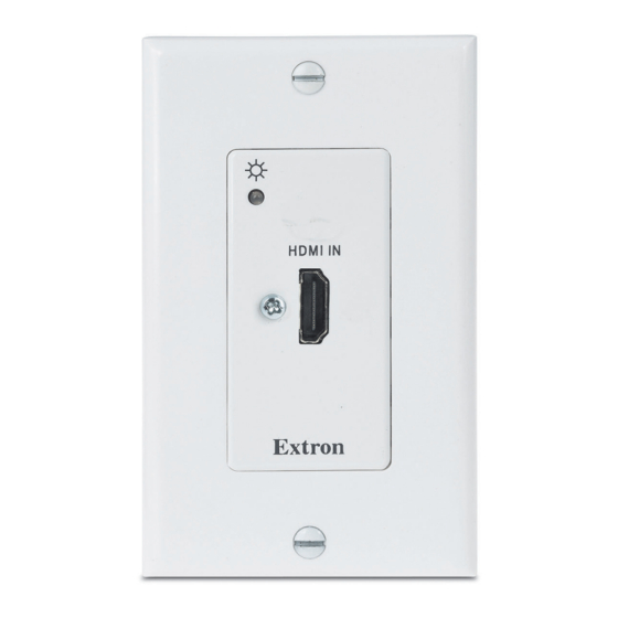
• Features About this Guide This guide describes how to install, operate, and configure the Extron DTP2 T 201 D extender transmitter. About the DTP2 T 201 D Extenders The Extron DTP2 T 201 D is a one-gang decorator-style transmitter for sending HDMI signals up to 330 feet (100 meters) over a shielded CATx cable to an Extron DTP-enabled product. -
Page 10: Twisted Pair Cable Advantages
NOTE: Do not use Extron UTP23SF-4 Enhanced Skew-Free AV UTP cable or STP201 cable to link the transmitter and receiver. The DTP2 T 201 D does not work properly with these cables. Transmission Distance The maximum transmission distance is determined by the resolution of the signal and the twisted pair cable, graphics card, and display used in the system. - Page 11 • DTP2 output is compatible with HDBaseT-enabled devices — The DTP2 T 201 D can be configured to send video and embedded audio to an HDBaseT-enabled display. Supports multiple embedded audio formats — The DTP2 T 201 D is compatible •...
-
Page 12: Installation And Operation
L’installation et l’entretien doivent être effectués par le personnel autorisé uniquement. The DTP2 T 201 D transmitters can be installed in a one-gang electrical wall box, or with a mud ring, with a decorator-style wallplate cover (supplied). The installation must conform to national and local building, electrical, and safety codes and to the size requirements of the wall plate. - Page 13 Feed the twisted pair cables and, if applicable, the power cables through the opening and through the wall box punch-out holes, securing them with cable clamps to provide strain relief. DTP2 T 201 D Transmitter • Installation and Operation...
-
Page 14: Mud Ring Installation
Wall Mounting Bracket Figure 4. Installing the Mud Ring Site Preparation and Wall Box Installation Follow steps 6 through 9 of starting on page 4, and Final Installation on the next page. DTP2 T 201 D Transmitter • Installation and Operation... -
Page 15: Final Installation
SEND POWER DTP2 T 201 D HDBT CONFIG DTP2 T 201 D DTP2 T 201 D Rear Panel Bottom View Figure 6. DTP2 T 201 D Transmitter Rear and Bottom Panels DTP2 T 201 D Transmitter • Installation and Operation... - Page 16 HDBaseT/DTP mode switch — Set this 2-position, recessed switch to configure the output between HDBaseT and DTP modes. When configured for HDBaseT, use an HDBaseT-compatible receiver. When configured for DTP, use a DTP-compatible receiver. DTP2 T 201 D Transmitter • Installation and Operation...
- Page 17 SEND POWER INPUT POWER LINK CONFIG OUTPUT DTP2 R 211 CATx Cable up to 330' (100 m) DTP2 T 201 D Local Power Supply Figure 7. Send Power Toggle Switch Configuration DTP2 T 201 D Transmitter • Installation and Operation...
-
Page 18: Tp Cable Termination And Recommendations
The DTP2 T 201 D Series of transmitters are compatible with shielded twisted pair (F/UTP, SF/UTP, and S/FTP) cable. NOTE: Do not use Extron UTP23SF-4 Enhanced Skew-Free AV UTP cable or STP201 cable to link the transmitter and receiver. The DTP2 T 201 D products do not work properly with these cables. Cable Recommendations Extron recommends using the following practices to achieve full transmission distances up to 330 feet (100 meters) and reduce transmission errors. -
Page 19: Power Supply Wiring
See figure 9 to wire the captive screw connector and secure the power cord to the extended tail of the connector. POWER --A MAX Smooth Ridges SECTION A–A 3/16" (5 mm) Max. Figure 9. Power Connector Wiring DTP2 T 201 D Transmitter • Remote Configuration and Control... - Page 20 • L’alimentation à distance est exclusivement réservée à un usage en intérieur. Un réseau utilisant une alimentation à distance ne peut pas être routé en extérieur. DTP2 T 201 D Transmitter • Installation and Operation...
-
Page 21: Operation
SIS commands or to upload a newer version of firmware. Connect a USB A to mini B cable between the transmitter USB Config port and a USB port of the PC. DTP2 T 201 D Transmitter • Installation and Operation... - Page 22 Figure 11. Connecting a PC to the DTP2 T 201 D Bottom Panel USB Port If this is the first time the DTP2 T 201 D has been connected to the PC, the Found New Hardware Wizard opens (see figure 12). The first screen offers to connect to Windows Update to search the web for the appropriate driver needed for the USB port to communicate with the transmitter.
-
Page 23: Resetting
Configure the transmitter using SIS Commands (see Remote Configuration and Control starting on page 16). Resetting Use the SIS command to reset the transmitter to its factory default settings (see Reset page 19). DTP2 T 201 D Transmitter • Installation and Operation... -
Page 24: Remote Configuration And Control
Remote Configuration and Control This section describes remote operation of the DTP2 T 201 D by using Simple Instruction Set (SIS) commands to control the DTP2 T 201 D transmitter. In addition this section provides information about updating your device to the latest firmware. -
Page 25: Timeout
First character must be a letter and the last character cannot be a hyphen = Firmware version to the second decimal place = Remote power = No remote power (Off) = DTP2 48 VDC (On) DTP2 T 201 D Transmitter • Remote Configuration and Control... -
Page 26: Command And Response Table For Sis Commands
View input/output remote View remote power RPWR setting on DTP2. power Rpwr Verbose mode 2/3 KEY: = Remote 0 = No remote power (Off); 1 = DTP2 48 VDC (On). DTP2 T 201 D Transmitter • Remote Configuration and Control... -
Page 27: Downloading And Updating Firmware
On the Extron website, mouse over the Download tab (see figure 15, Figure 15. Locating Firmware Loader Software ). The Software page opens (see Click on Firmware link in the drop-down list ( figure 16 on the next page). DTP2 T 201 D Transmitter • Remote Configuration and Control... -
Page 28: Installing Firmware Loader
Loader on the computer. The installation creates the necessary subfolders of C:\ Program Files and the necessary groups. It places the appropriate files into the correct group folder: C:\Program Files\Extron\FWLoader. DTP2 T 201 D Transmitter • Remote Configuration and Control... -
Page 29: Downloading Firmware To A Pc
Firmware Page with Alphabetic Navigation Bar Click the letter D from the alphabetic navigation bar ( Scroll down the page until you find the firmware for the DTP2 T 201 D. Click Release Notes for more information about the program (optional). -
Page 30: Updating Firmware
Figure 20. Opening Firmware Loader In the Add Device window, select the DTP2 T 201 D from the Device Names drop-down list. From the Connection Method drop-down list, select USB. Additional options appear. Make the appropriate selections for the USB connection. - Page 31 NOTE: The original factory-installed firmware is always available on the unit. If the attempted firmware upload fails for any reason, the unit DTP2 T 201 D reverts to the factory version. DTP2 T 201 D Transmitter • Remote Configuration and Control...
- Page 32 Extron USB Devi... Connected Figure 24. Firmware Loader Screen with a DTP2 T 201 D Added To remove a device from the Device section, do the following: Click on the names of the devices to be deleted, highlight them (see figure 24, Click on the Edit tab (see figure 25,...
- Page 33 ( DTP2 T 201 D 60-1741-53 1.00.001 dtp2t201d_A_v1.00.00... Extron USB Devi... Completed Figure 27. Firmware Upload Complete Close the Firmware Loader window when the upload is complete. DTP2 T 201 D Transmitter • Remote Configuration and Control...
-
Page 34: Reference Information
4.28" 3.06" for the installation (10.87 cm) (7.78 cm) surface. SURFACE CUT-OUT AREA FOR WALL MOUNT Top Panel Figure 28. Decorator-style Wallplate Template Dimensions Please measure the printed template before cutting. DTP2 T 201 D Transmitter • Reference Information... - Page 35 Extron Warranty Extron warrants this product against defects in materials and workmanship for a period of three years from the date of purchase. In the event of malfunction during the warranty period attributable directly to faulty workmanship and/ or materials, Extron will, at its option, repair or replace said products or components, to whatever extent it shall deem necessary to restore said product to proper operating condition, provided that it is returned within the warranty period, with proof of purchase and description of malfunction to: USA, Canada, South America,...
Need help?
Do you have a question about the DTP2 T 201 D and is the answer not in the manual?
Questions and answers