
Subscribe to Our Youtube Channel
Related Manuals for Extron electronics DTP2 T 202 FB


Summary of Contents for Extron electronics DTP2 T 202 FB
- Page 1 User Guide DTP Systems DTP2 T 202 FB Two-input Universal Twisted Pair Transmitter for Floor Boxes 68-2985-01 Rev. A 12 20...
- Page 2 Safety Instructions Safety Instructions • English Istruzioni di sicurezza • Italiano AVVERTENZA: Il simbolo, , se usato sul prodotto, serve ad This symbol, , when used on the product, is intended to WARNING avvertire l’utente della presenza di tensione non isolata pericolosa alert the user of the presence of uninsulated dangerous voltage within the all’interno del contenitore del prodotto che può...
- Page 3 より 『Extron Safety www.extron.com and Regulatory Compliance Guide』 (P/N 68-290-01) をご覧ください。 Copyright www.extron.com © 2020 Extron Electronics. All rights reserved. Trademarks All trademarks mentioned in this guide are the properties of their respective owners. The following registered trademarks ( ®...
- Page 4 FCC Class A Notice This equipment has been tested and found to comply with the limits for a Class A digital device, pursuant to part 15 of the FCC rules. The Class A limits provide reasonable protection against harmful interference when the equipment is operated in a commercial environment.
- Page 5 Software Commands Commands are written in the fonts shown here: ^AR Merge Scene,,0p1 scene 1,1 ^B 51 ^W^C.0 [01] R 0004 00300 00400 00800 00600 [02] 35 [17] [03] *X1&* X2)* X2#* X2! CE} E X! NOTE: For commands and examples of computer or device responses used in this guide, the character “0”...
-
Page 7: Table Of Contents
Floor Box ............. 12 Product Configuration Software Control .... 28 MK Electric CableLink Plus - Modular Installing the Software ........28 Floor Box ............. 13 Starting the Program ........31 Electraplan or PUK Floor Box ....... 13 DTP2 T 202 FB • Contents... - Page 8 DTP2 T 202 FB • Contents viii...
-
Page 9: Introduction
• About this Guide This guide describes how to install, operate, and configure the DTP2 T 202 FB, a floor box-mounted, switching, twisted pair transmitter. The DTP2 T 202 FB outputs a signal to a compatible DTP2 receiver, with a range of up 330 feet (100 M). -
Page 10: Control Communications
NOTE: Do not use Extron UTP23SF-4 Enhanced Skew-Free AV UTP cable or STP201 cable to link the receiver and transmitter. DTP2 and legacy DTP receivers and transmitters do not work properly with these cables. DTP2 T 202 FB • Introduction... -
Page 11: Features
AV environments. • Compatible with all DTP2 and legacy DTP receivers — The switching transmitters can be used with the Extron IN1608, DTP CrossPoint 84, and other DTP-enabled products to meet application requirements. DTP2 T 202 FB • Introduction... -
Page 12: Installation And Operation
• Installation Overview The DTP2 T 202 FB is to be installed in an Ackermann GB3 (OBO Bettermann), MK Electric CableLink Plus Modular, MK Electric CableLink Plus Single Pan, Electraplan, or PUK floor box. CAUTION: Failure to check the items listed below may result in personal injury or property damage. -
Page 13: Adapter Plates
NOTE: The 995242 adapter plate is only used for position 2 of the Ackermann GB3 (OBO Bettermann) floor box. Determine the position in the floor box to install the DTP2 T 202 FB. Each compatible floor box contains three positions to install devices (see figure 2 on the next page). - Page 14 995243 adapter plate to the mounting hole of the floor box position (see figure 4). MK Electric CableLink Plus Single Pan Floor Box Figure 4. Installing 995243 Adapter Plates DTP2 T 202 FB • Installation and Operation...
-
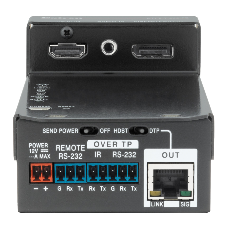
Page 15: Side Panel Features
Side Panel Connectors and Switches Below the Adapter Plates Power connector (see page 8) TP connector (see page 9) Remote RS-232 port Send Power switch Over TP RS-232/IR port TP function switch DTP2 T 202 FB • Installation and Operation... - Page 16 IR signal (up to 40 kHz), or both into this 3.5 mm, 5-pole direct RS-232 insertion connector for bidirectional RS-232 and IR communication (see Serial and IR port connectors to wire the connector). RS-232 and IR data can be transmitted simultaneously. DTP2 T 202 FB • Installation and Operation...
- Page 17 DTP2 and the Send Power switch on one of the units is in the Send position and Send Power on the other unit is in the position. Power DTP2 T 202 FB • Installation and Operation...
-
Page 18: Connectors Above The Adapter Plates
HDMI embedded audio HDMI Analog audio HDMI No audio Input 2 (DisplayPort) port — Plug a digital video input into this DisplayPort connector. The transmitter also accepts embedded digital audio on this connector. DTP2 T 202 FB • Installation and Operation... -
Page 19: Top Panel Features
(see Adapter Plates on page 5). Align the screw holes on the DTP2 T 202 FB with the screw holes on the adapter plates. Using the provided self-threading screws and washers, secure the DTP2 T 202 FB to... -
Page 20: Ackermann Gb3 (Obo Bettermann) Floor Box
Mounting the Unit into an MK Electric CableLink Plus - Single Pan Floor Box ATTENTION: • figure 2 Do not install the DTP2 T 202 FB in position 2 (see on page 6). • Ne pas installer le DTP2 T 202 FB en position 2 (voir l’illustration 2 sur la page 6). -
Page 21: Mk Electric Cablelink Plus - Modular Floor Box
Mounting the Unit into an MK Electric CableLink Plus - Modular Floor Electraplan or PUK Floor Box 995300 995300 12 V W ER M OT -2 32 Figure 14. Mounting the Unit into an Electraplan or PUK Floor Box DTP2 T 202 FB • Installation and Operation... -
Page 22: Connection And Wiring Details
• Ne pas étamer les conducteurs avant de les insérer dans le connecteur. Les câbles étamés ne sont pas aussi bien fixés dans le connecteur et pourraient être retirés. DTP2 T 202 FB • Installation and Operation... - Page 23 14) permettent de repérer le pôle négatif du cordon d’alimentation. To verify the polarity before connection, plug in the power supply with no load and check the output with a voltmeter. DTP2 T 202 FB • Installation and Operation...
-
Page 24: Serial And Ir Port Connectors
TP Cable Termination NOTE: Do not use Extron UTP23SF-4 Enhanced Skew-Free AV UTP cable or STP201 cable to link the switching transmitter and receiver. The DTP2 T 202 FB does not work properly with these cables. DTP2 T 202 FB • Installation and Operation... - Page 25 Supported cables The DTP2 T 202 FB is compatible with shielded twisted pair (STP) and unshielded twisted pair (U/UTP) cable. However, Extron strongly recommends that you use STP cable to achieve best performance. ATTENTION: • To ensure FCC Class A and CE compliance, STP cables and STP connectors are required.
-
Page 26: Operation
While holding the connector securely against the lacing bracket, use pliers or similar tools to tighten the tie wrap, then remove any excess length ( 5 ). Operation The DTP2 T 202 FB can be controlled only by SIS commands (see Simple Instruction Set Control... -
Page 27: Switch Modes
SIS commands on page 22) or the Product Configuration Software (see the PCS Help file). EDID To manage EDID on the DTP2 T 202 FB, use the Product Configuration Software (see Product Configuration Software Help file). Reset Mode Use the recessed Reset button on the top panel of the transmitter (see... -
Page 28: Remote Control
Remote Control This section contains information for remotely controlling the DTP2 T 202 FB switching transmitter. Topics in this section include: • Host Control Ports Simple Instruction Set Control • Product Configuration Software Control • Host Control Ports The transmitter is remotely controllable via its side panel Remote RS-232 port (“Serial Port”... -
Page 29: Simple Instruction Set Control
Command and response examples are shown throughout the table. The ASCII to HEX conversion table page 22 is for use with the command and response table. DTP2 T 202 FB • Remote Control... - Page 30 = Input 1 (HDMI) = Input 2 (DisplayPort) = Switch mode = Manual = Auto DisplayPort (default) = Auto HDMI = Input number (for audio configuration) = Always output = HDMI input = DisplayPort input DTP2 T 202 FB • Remote Control...
- Page 31 = Auto (default) = HDMI RGB full = HDMI YUV 444 limited = DVI RGB 444 = HDMI RGB limited = HDMI YUV 422 limited = Color bit depth mode = Auto = 8-bit DTP2 T 202 FB • Remote Control...
- Page 32 = Digital input = Analog input = Switch position = DTP2 = HDBT = Switch position = No remote power = Remote power = Over TP port mode = Pass-through (default) = Serial device control DTP2 T 202 FB • Remote Control...
- Page 33 = Firmware version with build number 0 = Clear/none = Verbose mode 1 = Verbose mode (default for RS-232 or USB) (default) 2 = Tagged responses for queries 3 = Verbose mode and tagged for queries DTP2 T 202 FB • Remote Control...
- Page 34 Predefined actions as strings, set aside in quotes, such as “ PwrOn”, “PwrOff”, or “ShowMe”. = Send result 0 = Fail (NAK), device not detected 1 = Success (ACK), device detected 2 = Unable to send DTP2 T 202 FB • Remote Control...
- Page 35 One or more user-selected elements (0 to 15) in the form of % followed by 2 hex digits (for example: %2A%07%FF) = CEC address byte In the form of % followed by 2 hex digits DTP2 T 202 FB • Remote Control...
-
Page 36: Product Configuration Software Control
2 2 2 2 2 2 2 2 Figure 19. Selecting the Download Tab Click the Firmware or Software link ( ). The main download page opens (see figure 20 on page 29). DTP2 T 202 FB • Remote Control... - Page 37 D D D D A A A A A A A A Figure 21. Log in Dialog Box Enter the E-Mail address and Password associated with your Extron insider account (see figure 21, DTP2 T 202 FB • Remote Control...
- Page 38 Firmware Loader — • Folder — C:\Program Files\Extron\FWLoader • Group folder — Extron Electronics Firmware Loader • Check for Firmware Loader Updates • Firmware Loader Help • Firmware Loader • Uninstall Firmware Loader DTP2 T 202 FB • Remote Control...
-
Page 39: Starting The Program
Starting the Program Start the Extron Product Configuration Software as follows: Click Start > Programs > Extron Electronics > Extron Product Configuration Software > Extron Product Configuration Software. The Product Configuration Software opens to the Device Discovery screen (see figure 23). - Page 40 Extron Electronics makes no further warranties either expressed or implied with respect to the product and its quality, performance, merchantability, or fitness for any particular use. In no event will Extron Electronics be liable for direct, indirect, or consequential damages resulting from any defect in this product even if Extron Electronics has been advised of such damage.
Need help?
Do you have a question about the DTP2 T 202 FB and is the answer not in the manual?
Questions and answers