
Related Manuals for Extron electronics DTP2 T 203


Summary of Contents for Extron electronics DTP2 T 203
- Page 1 User Guide DTP Systems DTP2 T 203 Three-input, Multi-format Switching Transmitter 68‑3117‑01 Rev. D 03 23...
- Page 2 Safety Instructions...
- Page 3 Copyright www.extron.com © 2019–2023 Extron. All rights reserved. Trademarks All trademarks mentioned in this guide are the properties of their respective owners. The following registered trademarks( ® , registered service marks( ), and trademarks( ) are the property of RGB Systems, Inc. or Extron Terms of Use page at www.extron.com): (see the current list of trademarks on the...
- Page 4 FCC Class A Notice This equipment has been tested and found to comply with the limits for a Class A digital device, pursuant to part 15 of the FCC rules. The Class A limits provide reasonable protection against harmful interference when the equipment is operated in a commercial environment.
- Page 5 Conventions Used in this Guide Notifications The following notifications are used in this guide: CAUTION: Risk of minor personal injury. ATTENTION : Risque de blessure mineure. ATTENTION: • Risk of property damage. Risque de dommages matériels. • NOTE: A note draws attention to important information. TIP: A tip provides a suggestion to make working with the application easier.
-
Page 7: Table Of Contents
Using the Command and Response Table ..44 Color Depth and Deep Color Support .... 21 Symbol Definitions ......... 44 Command and Response Table for SIS Commands ............48 Command and Response Table for CEC SIS Commands ............55 DTP2 T 203 • Contents... - Page 8 Inputs ............60 Outputs ............61 RS‑232 ............61 Roles and Permissions ........61 Firmware ............62 Equipment Mounting ......... 64 Mounting the DTP2 T 203 ......... 64 Tabletop Use ..........64 Mounting Kits ..........64 DTP2 T 203 • Contents viii...
-
Page 9: Introduction
USB, or LAN. Inputs can be selected by pressing the front panel buttons, enabling auto‑input switching, entering Simple Instruction Set (SIS) commands, or using Extron Product Configuration Software (PCS) via LAN or USB. An internal web page provides system status and some device configuration using a standard browser. DTP2 T 203 • Introduction... -
Page 10: Features
Remote power capability with DTP2 products — For simplified installation, the DTP2 T 203 can be remotely powered by a DTP2‑enabled product over the twisted pair connection. It can also be configured to provide power to the connected DTP2 receiver product. - Page 11 CEC insertion — A control processor can insert CEC commands via SIS ‑ Simple Instruction Set, to control devices connected at the HDMI output. Supports multiple embedded audio formats — The DTP2 T 203 is compatible with • a broad range of multi‑channel audio signals, providing reliable operation with HDMI sources.
-
Page 12: Application Diagram
• Extron Everlast power supply is covered by a 7-year parts and labor warranty. Application Diagram Figure 1 shows a typical application for a DTP2 T 203. Extron DTP2 T 203 Switcher IN1808 IPCP SA... -
Page 13: Installation
Connect a DTP or HDBT receiving device to the output ( Connect Over TP RS-232 and IR control. Connect a serial RS‑232 signal, a modulated IR signal, or both into this 3.5 mm, 5‑pole captive screw port ( ) for IR and bidirectional RS‑232 communication. DTP2 T 203 • Installation... -
Page 14: Rear Panel Features
A stereo audio connector consists of the tip, ring, and sleeve. HDMI and DisplayPort inputs — Connect HDMI or DisplayPort video sources LockIt Lacing Bracket Installation to these ports (see on page 15 to use the included lacing bracket). DTP2 T 203 • Installation... - Page 15 1.5A MAX RS-232 CONTACT IN TALLY OUT RS-232 LINK CONFIG OUTPUT HDMI HDMI 3 + V DTP2 R 211 CATx Cable up to 330' (100 m) Local Power Supply Figure 3. Send Power Toggle Switch Configuration DTP2 T 203 • Installation...
- Page 16 Position this switch BEFORE connecting the appropriate device to the TP connector. Failure to comply can damage the endpoint. • Positionnez le sélecteur AVANT de connecter l’appareil approprié au connecteur TP. Ne pas respecter cette procédure pourrait endommager le point de connexion. DTP2 T 203 • Installation...
- Page 17 Wiring on page 15 for wiring details). • RS-232— Plug a serial RS‑232 device into this 3.5 mm, 3‑pole captive screw connector for remote control of the DTP2 T 203 (see Remote RS-232 Control Wiring on page 13 for wiring details). LAN port — If desired, use an RJ‑45 cable to connect this port to a LAN via Ethernet...
-
Page 18: Connection Details
For connectors that require additional wiring details or recommendations, see the following sections pertaining to the type or connection. Power Supply Wiring A 12 VDC, 2.0 A power supply is provided with the DTP2 T 203 transmitter. Follow the instructions and figure 4 on page 11 to wire the 2‑pole captive screw connector to the... - Page 19 To verify the power cord polarity before connecting the plug, connect the power supply with no load and check the output with a voltmeter. Use the supplied tie wrap to strap the power cord to the extended tail of the connector. DTP2 T 203 • Installation...
-
Page 20: Tp Cable Termination For Dtp Communication
Do not comb the cable for the first 65 feet (20 meters), where cables are straightened, aligned, and secured in tight bundles. • Loosely place cables and limit the use of tie wraps or hook‑and‑loop fasteners. • Separate twisted pair cables from AC power cables. DTP2 T 203 • Installation... -
Page 21: Tp Cable Termination For Ethernet Communication
Connect the ground wire from the RS‑232 device into the G pin of the device. Plug the 3‑pole connector into the RS‑232 port on the rear panel of the transmitter. Connect the other end of the cable to a control system or the device being controlled. DTP2 T 203 • Installation... -
Page 22: Over Tp Rs-232 And Ir Control Wiring
The IR Tx and Rx line pairs and the RS‑232 Tx and Rx line pairs must each cross once between their connectors and the source or destination. The length and preparation of exposed wires is important (see the ATTENTION: • page 11). DTP2 T 203 • Installation... -
Page 23: Contact In Port Wiring
( The screw does not have to be removed. Place the LockIt lacing bracket on the screw and against the HDMI connector, then tighten the screw to secure the bracket ( DTP2 T 203 • Installation... - Page 24 Loosely place the included tie wrap around the HDMI connector and the LockIt lacing bracket ( While holding the connector securely against the lacing bracket, use pliers or similar tools to tighten the tie wrap, then remove any excess length ( DTP2 T 203 • Installation...
-
Page 25: Operation
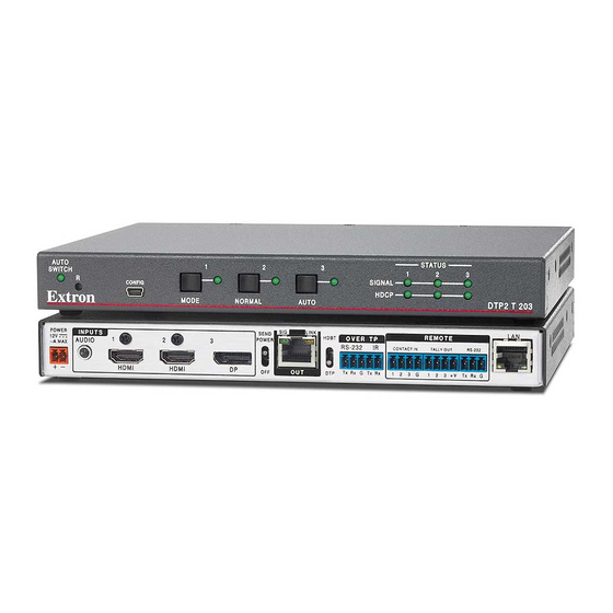
Signal Status LEDs — Lights when a source is connected to the input port. HDCP Status LEDs — Lights if the currently selected input requires HDCP and the connected output device has been successfully authenticated. DTP2 T 203 • Operation... -
Page 26: Operation
The factory configured password for all accounts on this device have been set • to the device serial number. Passwords are case sensitive. If the switcher resets, the password reverts to the default, extron. A new password would need to be configured to secure the device. DTP2 T 203 • Operation... -
Page 27: Front Panel Lockout (Executive Mode)
CONFIG HDCP MODE NORMAL AUTO DTP2 T 203 DTP2 T 203 Front Panel Figure 10. USB Port Connection Enabling Auto‑Input Switching The DTP2 T 203 can automatically select an active, connected input based on a configured priority using auto switching. When auto switch is enabled, it can be configured in the two following priorities via... -
Page 28: Edid Minder
EDID is retained until a reset is initiated, when it reverts back to the default EDID. Hot Plug Detect (HPD) HPD remains high on all inputs while the unit is powered on. The HPD drops low only while EDID is updated. DTP2 T 203 • Operation... -
Page 29: Hdcp
Force 8-bit — This mode always sets the switcher to output video with 8‑bit color depth. This can be changed via SIS commands (see Video Color Bit Depth on page 49) or (Color Bit Depth on page 31). DTP2 T 203 • Operation... -
Page 30: Audio Configuration
TMDS Output Audio Configuration The embedded TMDS audio output over the TP output can be enabled or disabled via SIS commands (see TMDS (HDMI) Output Audio Format on page 48) or PCS (see Mute Embedded Audio on page 31). DTP2 T 203 • Operation... -
Page 31: Product Configuration Software
Product Configuration Software The DTP2 T 203 switcher can be easily configured using Extron Product Configuration Software (PCS). This section describes: • Software/Firmware Installation Connecting to PCS • • Software Overview • Using PCS for the Switcher Software/Firmware Installation Visit www.extron.com... - Page 32 Double‑click the executable file and follow the on‑screen directions to install the software. For firmware: To install via PCS, see Updating the Firmware on page 39. To install via internal web page, see Firmware on page 62. DTP2 T 203 • Product Configuration Software...
-
Page 33: Connecting To Pcs
Click in the IP Address field to edit the address. Click Apply to complete and close. Alternatively, click Apply and Connect to complete and connect to the device. Click Cancel to close the box without changes. Figure 16. Communication Settings DTP2 T 203 • Product Configuration Software... -
Page 34: Tcp/Ip Panel
), enter the port number or leave the field blank. PCS scans for the port if blank. NOTE: Select the Show Characters checkbox ( ) to display the password characters. Click the Connect button ( ). A new device tab opens. DTP2 T 203 • Product Configuration Software... -
Page 35: Offline Device Preview
NOTE: The device tab (see the image below) has a grayed out indicator DTP2 T 203 (circle) to indicate that there is no device connected and the software is running in offline configuration mode. DTP2 T 203 • Product Configuration Software... -
Page 36: Software Overview
From the Software menu, select Tutorial. The Tutorial dialog box opens. Click the I Get It! button to close the dialog box. Extron PCS Help Open the PCS help file for general PCS operations. From the Software menu, select Extron PCS Help. DTP2 T 203 • Product Configuration Software... - Page 37 Click the Close Session(s) and Exit button ( ) to disconnect the software from connected devices, close all offline device tabs, and close the software. Alternatively, click the Cancel button ( ) to leave the software open. DTP2 T 203 • Product Configuration Software...
-
Page 38: Using Pcs For The Switcher
HDCP with the source device, if the source requires HDCP encryption. HDCP Authorized — Select this checkbox to turn the HDCP Authorized on (default) or off. When disabled (Off), the DTP2 T 203 does not display content that requires HDCP, and displays a green screen. - Page 39 5V Mode — Disable or enable 5 V Hot‑Plug. Select Auto or Enabled. Mute Embedded Audio — Select this button to mute the audio embedded in the output signal. DTP2 T 203 • Product Configuration Software...
-
Page 40: Edid Minder
) to assign EDID to one or more selected inputs, OR • Drag and drop EDID image from the Favorites, Available EDID, or Connected • Outputs panels to one or more selected inputs. DTP2 T 203 • Product Configuration Software... - Page 41 ). The EDID is added to the Available EDID panel. EDID Report Click the EDID Report tab (see figure 30, ) to view the EDID information of the sources connected to the inputs. Figure 30. EDID Report Panel DTP2 T 203 • Product Configuration Software...
-
Page 42: General Settings
• Version Click the Edit Communication Settings button to open the Communication Settings dialog box to enter device settings for Ethernet connections (see Communication Settings on page 35 Figure 32. Unit Information for details). DTP2 T 203 • Product Configuration Software... - Page 43 Figure 34. Hostname HDCP Notification Figure 35. HDCP Notification Panel Select the desired radio button to designate the display color when HDCP content is sent to a non‑compliant display: Black or Green (see figure 35). DTP2 T 203 • Product Configuration Software...
- Page 44 NOTE: On the DTP2 output, CEC Communications passes through only when connected to a DTP2 or DTP standalone receiver. CEC Communications does not pass through when connected to a non‑standalone DTP2 or DTP receiver. DTP2 T 203 • Product Configuration Software...
- Page 45 Click the RS-232 tab to view the RS-232 Insertion panel (see figure 41, Figure 41. General Settings - RS-232 Tab This panel allows the user to view and change the Starting Port ( ) and general port configuration of the RS‑232. DTP2 T 203 • Product Configuration Software...
-
Page 46: Av Controls
Click Apply to save the changes. AV Controls The AV Controls panel is available on all of the configuration pages for the DTP2 T 203 (see figure 43). It can be used to switch inputs, view active inputs , and mute or unmute video and audio signals. -
Page 47: Device Menu
• part number and firmware version of the connected device. Updating the Firmware Firmware for the DTP2 T 203 can be updated using PCS. Updates to the DTP2 T 203 firmware are made available periodically via the Extron website. The current firmware version can be queried by entering the SIS Q command via the RS‑232 or USB interface... - Page 48 Click Close. The software returns to the Device Discovery window. Select DTP2 T 203 from the Device Discovery. A connection must be re‑established with the device before continuing to use the software.
-
Page 49: Sis Configuration And Control
Host Control Ports Rear Panel RS‑232 Port The DTP2 T 203 has a rear panel serial port that can be connected to a host device such as a computer running Extron DataViewer, available at www.extron.com. The port makes serial control of the switcher possible (see Remote RS-232 Control Wiring on page 13... -
Page 50: Establishing A Connection
Telnet session must be in verbose mode 1 or 3. In verbose mode 1 or 3, the Telnet socket reports changes in messages that resemble SIS command responses. Front panel changes are also sent to users who are in verbose mode. DTP2 T 203 • SIS Commands... -
Page 51: Simple Instruction Set Control
No response is required from the host. The switcher sends the following message when it is first powered on: (C) Copyright 2019, Extron Electronics DTP2 T 203, Vn.nn, 60-1659-52 Vn.nn is the firmware version number. •... -
Page 52: Using The Command And Response Table
0 = Unmute video and sync (default) 1 = Mute video to black screen 2 = Mute video and sync = Video color bit depth mode 1 = Auto based on sink EDID (default) 2 = Force truncation to 8‑bit DTP2 T 203 • SIS Commands... - Page 53 2 = 5 V always enabled (default) = Tally pin mode on channel mute: 0 = Always on (default) 1 = Off when muted 2 = Blink when muted = Set Date/Time (MM/DD/YY-HH:MM:SS) Example: 04/21/19‑10:54:00 DTP2 T 203 • SIS Commands...
- Page 54 = Over TP IR control 1 = Over TP pass through (default) 2 = Over TP serial device control = Auto Switch Priority 1 = input 1 2 = input 2 3 = input 3 DTP2 T 203 • SIS Commands...
- Page 55 = Prefix (subnet mask bits). Subnet 255.255.0.0 is represented as a Prefix value by /16. Default subnet mask bits response for esc CISG command (on IPv4) = /16: (IPV6 is TBD). NOTE: Unless otherwise indicated, commands are not case‑sensitive. DTP2 T 203 • SIS Commands...
-
Page 56: Command And Response Table For Sis Commands
TMDS (HDMI) Output Audio Format Enable TMDS output audio O1AFMT AfmtO1 Disable TMDS output audio O0AFMT AfmtO0 Query TMDS output audio setting OAFMT AfmtO Verbose mode 2/3 KEY: = Status = Off, disable = On, enable DTP2 T 203 • SIS Configuration and Control... - Page 57 X1%] Verbose mode 2/3 KEY: = Verbose mode: = Clear/none (default for IP) = Verbose mode (default for serial/USB) = Tagged responses for queries = Verbose mode and tagged responses for queries DTP2 T 203 • SIS Configuration and Control...
- Page 58 Verbose mode 2/3 KEY: = TMDS output format: = Auto (default) = DVI RGB 444 = HDMI RGB “Full” = HDMI RGB “Limited” = HDMI YUV 444 “Limited” = HDMI YUV 422 “Limited” DTP2 T 203 • SIS Configuration and Control...
- Page 59 Default subnet mask = = Password: Maximum length is up to 128 characters. All human‑readable characters are permitted except “ ”. Passwords are case‑sensitive and cannot be a single space. DTP2 T 203 • SIS Configuration and Control...
- Page 60 = Parity Odd, Even, None, Mark, Space (Only the first letter is required) = Data bits: through (default = = Stop bits: (default = 65000 = Port timeout intervals: second intervals: seconds). Default is seconds = minutes. DTP2 T 203 • SIS Configuration and Control...
- Page 61 2HSTM Hstm Query host control port mode X3&] HSTM X3&] Hstm Verbose mode 2/3 KEY: X3& = Over TP IR control: = Over TP pass‑through (default) = Over TP serial device control. DTP2 T 203 • SIS Configuration and Control...
- Page 62 = Inputs: = Status: = Disable (default) = Enable. = Auto switch: = Disable (default) = User‑defined priority = Last‑connected input = Video mute: = Unmute (default) = Mute output = Mute sync DTP2 T 203 • SIS Configuration and Control...
-
Page 63: Command And Response Table For Cec Sis Commands
) in the form of percent sign followed by 2 hex digits %2A%07%FF (Example: = CEC address byte: In the form of percent sign followed by 2 hex digits (Example: = Extron output ( ) to TV ( DTP2 T 203 • SIS Configuration and Control... - Page 64 4 hexadecimal digits in the form of (Example: = CEC address byte: In the form of percent sign followed by 2 hex digits (Example: = Extron output ( ) to TV ( DTP2 T 203 • SIS Configuration and Control...
-
Page 65: Internal Web Page
The DTP2 T 203 features an internal web server, displayed as a web page. This page allows you to monitor and adjust certain settings of the DTP2 T 203 via a LAN or WAN connection through the rear panel LAN (RJ‑45) port, using a web browser such as the latest versions of... -
Page 66: Web Pages Panel
Web Pages Panel The DTP2 T 203 internal web page provides an overall, read‑only view of the status of the transmitter, with some editable fields (see figure 49). Figure 49. Web Page The panels are: Device Info Inputs Firmware Device Status... -
Page 67: Device Status
The Device Status Settings dialog box opens (see figure 53). Make the desired changes. Figure 53. Device Status Settings Click SAVE. Alternatively, click SYNC TO PC (see figure 52, ) to set the date and time according to your PC. DTP2 T 203 • Internal Web Pages... -
Page 68: Network Settings
The Inputs panel displays the status of the connected inputs (see figure 56). Click 2 MORE to see the full Connected Devices panel showing the remaining two inputs and their format (see figure 57). Figure 56. Inputs Figure 57. Connected Devices DTP2 T 203 • Internal Web Pages... -
Page 69: Outputs
• The default admin ID is admin and the default user ID is user. • An indicator of the current login status is shown on the top right corner of the main screen. DTP2 T 203 • Internal Web Pages... -
Page 70: Firmware
Click SAVE. Firmware The Firmware panel displays the current firmware version and the date it was last updated (see figure 62). Update the firmware on the DTP2 T 203 from this panel. Figure 62. Firmware Panel DTP2 T 203 • Internal Web Pages... - Page 71 ). The firmware is uploaded to the connected device. NOTE: The original factory‑installed firmware is permanently available on the DTP2 T 203. If the attempted firmware upload fails for any reason, the switcher reverts to the factory version. DTP2 T 203 • Internal Web Pages...
-
Page 72: Equipment Mounting
“UL Rack‑Mounting Guidelines” starting below. UL Rack‑Mounting Guidelines The following Underwriters Laboratories (UL) requirements pertain to the installation of the DTP2 T 203 into a rack. CAUTION: • Elevated operating ambient temperature — If the equipment is installed in a closed or multi‑unit rack assembly, the operating ambient temperature of the rack... - Page 73 Consignes UL pour le montage en rack Les consignes UL (« Underwriters Laboratories ») suivantes concernent l’installation en rack d’un boîtier DTP2 T 203 : ATTENTION: • Température ambiante élevée — En cas d’installation de l’équipement dans un rack fermé ou composé de plusieurs unités, la température du rack peut être supérieure à...
- Page 74 Extron Warranty Extron warrants this product against defects in materials and workmanship for a period of three years from the date of purchase. In the event of malfunction during the warranty period attributable directly to faulty workmanship and/ or materials, Extron will, at its option, repair or replace said products or components, to whatever extent it shall deem necessary to restore said product to proper operating condition, provided that it is returned within the warranty period, with proof of purchase and description of malfunction to: USA, Canada, South America,...
Need help?
Do you have a question about the DTP2 T 203 and is the answer not in the manual?
Questions and answers