
Related Manuals for Extron electronics DTP2 T/R 211


Summary of Contents for Extron electronics DTP2 T/R 211
- Page 1 User Guide DTP Systems DTP2 T/R 211 HDMI Twisted Pair Transmitters and Receivers 68‑2938‑01 Rev. D 11 21...
- Page 2 Safety Instructions...
- Page 3 Copyright www.extron.com © 2019‑2021 Extron. All rights reserved. Trademarks All trademarks mentioned in this guide are the properties of their respective owners. The following registered trademarks( ® , registered service marks( ), and trademarks( ) are the property of RGB Systems, Inc. or Extron (see the current list of trademarks on the page at Terms of Use...
- Page 4 FCC Class A Notice This equipment has been tested and found to comply with the limits for a Class A digital device, pursuant to part 15 of the FCC rules. The Class A limits provide reasonable protection against harmful interference when the equipment is operated in a commercial environment.
- Page 5 Conventions Used in this Guide Notifications The following notifications are used in this guide: CAUTION: Risk of minor personal injury. ATTENTION : Risque de blessure mineure. ATTENTION: • Risk of property damage. • Risque de dommages matériels. NOTE: A note draws attention to important information. Software Commands Commands are written in the fonts shown here: ^AR Merge Scene,,Op1 scene 1,1 ^B 51 ^W^C...
-
Page 7: Table Of Contents
Front Panel Features ........15 Connecting to the Front Panel USB Port ..17 Extron Warranty ........35 Resetting ............18 Analog Audio Embedding (Transmitter) ..19 HDMI Audio De‑embedding (Receiver) ... 19 DTP2 T/R 211 • Table of Contents... - Page 8 DTP2 T/R 211 • Table of Contents viii...
-
Page 9: Introduction
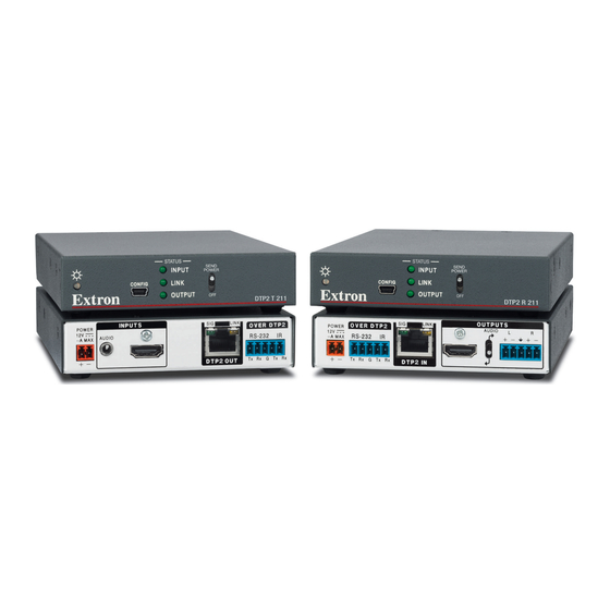
The DTP2 211 transmitter and receiver are housed in 1 inch tall, quarter rack width, 6 inches deep metal enclosures. They can be set on a tabletop, mounted in a rack, or under or through furniture. The receiver can also be mounted on a projector bracket. DTP2 T/R 211 • Introduction... -
Page 10: Control Communications
Receives HDMI plus control and analog audio up to 330 feet (100 meters) over • a shielded CATx cable — The DTP2 R 211 provides high reliability and maximum performance on an economical and easily installed cable infrastructure. DTP2 T/R 211 • Introduction... - Page 11 LCD flat‑panel display. • Includes LockIt HDMI cable lacing brackets — LockIt lacing brackets are used to secure HDMI cables connected to the HDMI input and output connectors, preventing accidental disconnection of the cables. DTP2 T/R 211 • Introduction...
- Page 12 External Extron Everlast power supply included (with the transmitter only) — Provides worldwide power compatibility with high‑demonstrated reliability and low power consumption. Extron Everlast Power Supply is covered by a 7-year parts and labor warranty. • DTP2 T/R 211 • Introduction...
-
Page 13: Installation And Operation
Connect control devices. Connect your computer to the front panel Configuration port (see figure 9, on page 15 on the transmitter and receiver) to configure and control the transmitter and receiver via SIS commands. Power on the output display. DTP2 T/R 211 • Installation and Operation... -
Page 14: Connections
Power inlet — Plug the included external 12 VDC power supply into either this 2‑pole inlet or the power inlet on the receiver (see figure 3, on page 8, and Power Supply Wiring on page 12 to wire the connector). DTP2 T/R 211 • Installation and Operation... - Page 15 Over DTP2 RS-232 and IR port — Connect a serial RS‑232 signal, a modulated IR signal, or both to this 3.5 mm, 5‑pole captive screw port for bidirectional RS‑232 and IR communication (see RS-232 and IR Connector Wiring on page 14 to wire the connector). DTP2 T/R 211 • Installation and Operation...
-
Page 16: Receiver Rear Panel Connections
Set the toggle switch to the UP position for the analog input from the TRS audio port on the Tx unit to be transported simultaneously with the digital embedded HDMI audio and output on the captive screw output (see figure 3, HDMI Audio De-embedding (Receiver) on page 19). DTP2 T/R 211 • Installation and Operation... - Page 17 La longueur idéale est de 5 mm (3/16 inches). S’ils sont trop longs, les câbles exposés pourraient se toucher et provoquer un court‑ circuit. S’ils sont trop courts, ils peuvent être tirés facilement, même s’ils sont correctement serrés par les borniers à vis. DTP2 T/R 211 • Installation and Operation...
-
Page 18: Securing The Hdmi Connector
Loosely place the included tie wrap around the HDMI connector and the LockIt lacing bracket ( While holding the connector securely against the lacing bracket, use pliers or similar tools to tighten the tie wrap, then remove any excess length ( DTP2 T/R 211 • Installation and Operation... -
Page 19: Tp Cable Termination And Recommendations
Do not comb the cable for the first 65 feet (20 meters), where cables are straightened, aligned, and secured in tight bundles. Loosely place cables and limit the use of tie wraps or hook‑and‑loop fasteners. • • Separate twisted pair cables from AC power cables. DTP2 T/R 211 • Installation and Operation... -
Page 20: Power Supply Wiring
• Utilisez toujours une source d’alimentation fournie ou recommandée par Extron. L’utilisation d’une source d’alimentation non autorisée annule toute certification de conformité réglementaire, et peut endommager la source d’alimentation et l’unité. DTP2 T/R 211 • Installation and Operation... - Page 21 Remote power is intended for indoors use only. No part of a network that uses remote power can be routed outdoors. L’alimentation à distance est exclusivement réservée à un usage en intérieur. Un • réseau utilisant une alimentation à distance ne peut pas être routé en extérieur. DTP2 T/R 211 • Installation and Operation...
-
Page 22: Rs-232 And Ir Connector Wiring
The IR Tx and Rx line pair and the RS‑232 Tx and Rx line pair must each cross once between this connector and the source or destination. • The length and preparation of exposed wires is important (see the ATTENTION notifications on the previous page for details). DTP2 T/R 211 • Installation and Operation... -
Page 23: Operations
DTP2 uniquement. S’il est connecté à un autre appareil, veuillez positionner l’interrupteur à bascule sur « DOWN » (OFF). Si l’interrupteur n’est pas positionné sur OFF, vous risquez d’entraîner la défaillance de l’appareil Legacy DTP connecté. DTP2 T/R 211 • Installation and Operation... - Page 24 INPUT INPUT POWER POWER LINK LINK CONFIG CONFIG OUTPUT OUTPUT DTP2 T 211 DTP2 R 211 CATx Cable up to 330' (100 m) Local Power Supply Figure 10. Send Power Toggle Switch Configuration DTP2 T/R 211 • Installation and Operation...
-
Page 25: Connecting To The Front Panel Usb Port
Click on the appropriate radio button (see figure 12): • Select the Yes, this time only radio button ( ) if you want your computer to connect to Windows Update only this one time. DTP2 T/R 211 • Installation and Operation... -
Page 26: Resetting
Configure the transmitter or receiver as required using SIS Commands (see Remote Control starting on page 20). Resetting Use the SIS command to reset the transmitter or receiver to its factory default settings (see Reset on page 23). DTP2 T/R 211 • Installation and Operation... -
Page 27: Analog Audio Embedding (Transmitter)
• • UP — HDMI digital audio pass‑through and analog audio over DTP2. NOTE: Whether the audio configuration switch is UP or DOWN, the embedded digital audio on the HDMI signal remains intact. DTP2 T/R 211 • Installation and Operation... -
Page 28: Remote Control
(CR/LF = ), which signals the end of the response character string. When the transmitter or receiver is first powered on, it sends the message: (c) Copyright 2019, Extron Electronics DTP2 T/R 211, V 60‑ x.xx xxxx‑xx •... -
Page 29: Symbol Definitions
1 = DOWN —De‑embedded audio from the HDMI signal is output on the analog audio output (default). 2 = UP — Analog audio passed from the TX is output on the analog audio output. DTP2 T/R 211 • Remote Control... -
Page 30: Command And Response Table For Sis Commands
Firmware build with 2 x.xx decimals. Query firmware version w/ *Q/q x.xx.xxxx build Query detailed firmware 0Q/q version Query build and any special 20Q/q build text KEY: = Firmware version to the second decimal place. DTP2 T/R 211 • Remote Control... - Page 31 • • 211 ] Inf01*DTP2 DTP2 R 211 DTP2•R•211 • • Verbose mode 2/3 211 ] Inf01*DTP2 Query model description 2I/i DTP2•HDMI•4K60•Transmitter DTP2 T 211 Inf02*DTP2•HDMI•4K60•Transmitter Verbose mode 2/3 DTP2 R 211 DTP2•HDMI•4K60•Receiver Verbose mode 2/3 Inf02*DTP2•HDMI•4K60•Receiver Reset Reset ZXXX DTP2 T/R 211 • Remote Control...
-
Page 32: Downloading And Updating Firmware
Click on Software link in the drop‑down menu( Figure 16. Software Page with Alphabetic Navigation Bar On the bottom of the page, click on the F link (see figure 16, Locate Firmware Loader (see figure 17 on page 25 ). DTP2 T/R 211 • Remote Control... -
Page 33: Installing Firmware Loader
On the Extron website, mouse over the Download tab in the menu bar along the top of the page (see figure 18, Figure 18. Locate Firmware for DTP2 211 Transmitter or Receiver Click Firmware in the drop‑down menu ( The Firmware page opens (see figure 19 on page 26). DTP2 T/R 211 • Remote Control... -
Page 34: Updating Firmware On A Dtp2 211 Device
Open the Firmware Loader via the Firmware Loader icon installed during the download (optional) or your desktop Start menu by making the following selections: Start > All Programs > Extron Electronics > Firmware Loader > Firmware Loader The Firmware Loader window opens. The Add Device... window opens in front (see figure 20). - Page 35 The extension of the firmware file must be .s19. Opening a file with an • incorrect extension may cause the device to stop functioning. L’extension du fichier firmware doit être .s19. Si un fichier est ouvert avec • une mauvaise extension, l’appareil peut arrêter de fonctionner. DTP2 T/R 211 • Remote Control...
- Page 36 Firmware Loader Screen with a DTP2 T 211 Added To remove a device from the Device section, do the following: Click on the names of the devices to be deleted, highlight them (see figure 24, DTP2 T/R 211 • Remote Control...
- Page 37 ) and in the Status column ( above the progress bar ( 60-1631-52 1.00.001 DTP2 T 211 dtp2t211_A_v1.00.00... Extron USB Devi... Completed Figure 27. Firmware Upload Complete Close the Firmware Loader window when the upload is complete. DTP2 T/R 211 • Remote Control...
-
Page 38: Reference Information
The devices are compatible with the Extron Half Rack shelf system HRB 109, Extron UTS under the table shelf system, Extron rack shelves RSU 126, and MBU 125 under the table shelf brackets. DTP2 T/R 211 • Reference Information... -
Page 39: Ul Rack-Mounting Guidelines
For rack mounting, see UL Rack‑Mounting Gudielines starting below. UL Rack‑Mounting Guidelines The following Underwriters Laboratories (UL) requirements pertain to the installation of the DTP2 T/R 211 into a rack. CAUTION: • Elevated operating ambient temperature — If the equipment is installed in a closed or multi‑unit rack assembly, the operating ambient temperature of the rack... -
Page 40: Internal Settings
Each unit requires a local power supply. • If the 48 VDC remote power jumper is off, DTP2 211 unit cannot remotely power the other unit. Each unit requires a local power supply. DTP2 T/R 211 • Reference Information... - Page 41 Reinstall both units in their racks or other installation option (see Mounting the Transmitter or Receiver on page 30). If shielded cable is used, disconnect the cable shield from the connector at either end of the cable. DTP2 T/R 211 • Reference Information...
- Page 42 • Utilisez toujours une source d’alimentation fournie ou recommandée par Extron. L’utilisation d’une source d’alimentation non autorisée annule toute certification de conformité réglementaire, et peut endommager la source d’alimentation et l’unité. DTP2 T/R 211 • Reference Information...
-
Page 43: Extron Warranty
Extron Electronics makes no further warranties either expressed or implied with respect to the product and its quality, performance, merchantability, or fitness for any particular use. In no event will Extron Electronics be liable for direct, indirect, or consequential damages resulting from any defect in this product even if Extron Electronics has been advised of such damage.
Need help?
Do you have a question about the DTP2 T/R 211 and is the answer not in the manual?
Questions and answers