Advertisement
Quick Links
DTP2 T 201 D Series • Setup Guide
This setup guide provides instructions for an experienced installer to set up the Extron DTP2 T 201 D Transmitter.
Top View
LINK
HDMI IN
D
G
a
DTP2 T 201 D
Front Panel
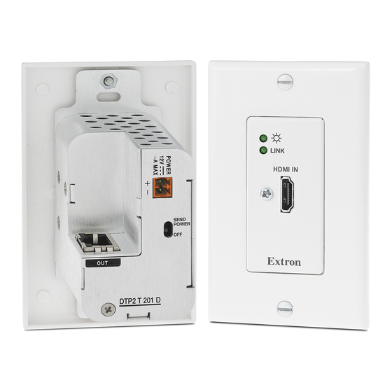
Figure 1.
DTP2 T 201 D Front and Rear Panels
Installation
Step 1 — Disconnect Power
Disconnect all equipment from power sources.
Step 2 — Prepare the Mounting Surface
NOTES:
•
Use a wall box with a depth of at least 3.0 inches (7.6
cm). Alternatively, the included mud ring (MR 100) can
be used.
•
For more information, see the full product user guide at
www.extron.com. The installation must comply with
the National Electrical Code and all applicable local
codes.
Refer to figure 2 for the following steps.
a.
Place the wall box against the installation surface and
mark the opening guidelines.
b.
Cut out the material from the marked area.
c.
Secure the wall box with 10-penny nails or #8 or #10 screws, leaving the front edge flush with the surface.
d.
Run all required cables (see steps
e.
Do not install the transmitter into the wall box until a later step.
TIP: To ensure a proper fit the unit in the junction box, do not install boots on TP cables and RJ-45 connectors.
Step 3 — Connect Input to the Transmitter
Connect an HDMI cable between the HDMI input connector and the output of the digital video source (see figure 1,
C
SEND
B
POWER
OFF
OUT
DTP2 T 201 D
CONFIG
E
DTP2 T 201 D
DTP2 T 201 D
Rear Panel
Bottom View
4
and 5, on the next pages) and secure them with cable clamps.
A
B
C
D
E
F
F
HDBT
G
DTP
Wall Stud
Signal
Output
Cable
Screws
or Nails
Figure 2.
Typical DTP2 T 201 D Wall Installation
HDMI input connector
Send Power mode switch
Power connector
DTP OUT connector
USB Configuration port
HDBaseT/DTP mode switch
Grounding Screw
K
L IN
IN
M I
H D
a
Extron
DTP2 T 201 D
Transmitter
Decorator-Style Faceplate
A
).
1
Advertisement

Related Manuals for Extron electronics DTP2 T 201 D Series


Summary of Contents for Extron electronics DTP2 T 201 D Series
- Page 1 DTP2 T 201 D Series • Setup Guide This setup guide provides instructions for an experienced installer to set up the Extron DTP2 T 201 D Transmitter. Top View HDMI input connector Send Power mode switch LINK Power connector HDMI IN...
- Page 2 DTP2 T 201 D • Setup Guide (Continued) Step 4 — Set DTP/HDBT and SEND POWER Switches Connect an RJ-45 DTP or HDBT receiving device to the output (see figure 1, on the previous page) for either DTP or HDBT model. For DTP2 series receivers, set the DTP/HDBT switch ( ) to the UP (SEND POWER) ) to DTP and the SEND POWER switch (...
- Page 3 Step 5 — Run Cable Between Units NOTE: The DTP2 T 201 D product can transmit video, control, and audio (if applicable) signals up to 330 feet (100 m). Connect the transmitter output (see figure 1, ) to the receiver input using shielded twisted pair (STP) cable. For optimal performance, Extron highly recommends the following: ATTENTION: •...
- Page 4 Application Diagrams The following figures show typical applications for the DTP2 T 201 D transmitters. eBUS IR/S RELAYS LIMIT OVER INPUTS OUTPUTS INPUTS LOOP MENU SIGNAL 1 2 3 4 5 6 7 8 LOGO HDCP DTP2 CONFIG ENTER VOLUME HOLD FOR 720p/1080p IN1808...
Need help?
Do you have a question about the DTP2 T 201 D Series and is the answer not in the manual?
Questions and answers