
Related Manuals for Extron electronics DTP2 T 203


Summary of Contents for Extron electronics DTP2 T 203
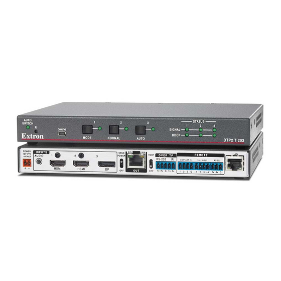
- Page 1 User Guide DTP Systems DTP2 T 203 Three-input, Multi-format Switching Transmitter 68‑3117‑01 Rev. A 08 19...
- Page 2 Safety Instructions Safety Instructions • English Istruzioni di sicurezza • Italiano AVVERTENZA: Il simbolo, , se usato sul prodotto, serve ad WARNING: This symbol, ,when used on the product, is avvertire l’utente della presenza di tensione non isolata pericolosa intended to alert the user of the presence of uninsulated dangerous all’interno del contenitore del prodotto che può...
- Page 3 ついては、 エクス トロンのウェブサイ ト より 『Extron Safety www.extron.com and Regulatory Compliance Guide』 (P/N 68‑290‑01) をご覧ください。 Copyright © 2019 Extron Electronics. All rights reserved. Trademarks All trademarks mentioned in this guide are the properties of their respective owners. The following registered trademarks( ®...
- Page 4 FCC Class A Notice This equipment has been tested and found to comply with the limits for a Class A digital device, pursuant to part 15 of the FCC rules. The Class A limits provide reasonable protection against harmful interference when the equipment is operated in a commercial environment. This equipment generates, uses, and can radiate radio frequency energy and, if not installed and used in accordance with the instruction manual, may cause harmful interference to radio communications.
- Page 5 Conventions Used in this Guide Notifications The following notifications are used in this guide: CAUTION: Risk of minor personal injury. ATTENTION : Risque de blessure mineure. ATTENTION: • Risk of property damage. • Risque de dommages matériels. NOTE: A note draws attention to important information. TIP: A tip provides a suggestion to make working with the application easier.
-
Page 7: Table Of Contents
Rear Panel Features ..........6 Updating Firmware Using PCS ......35 Wiring Connections ........... 10 Downloading the DTP2 T 203 Firmware ..35 Power Connector .......... 10 Loading the Firmware to the Switcher .... 36 Wiring the LAN Connector ......12 Wiring the TP Connector and Cable SIS Commands ......... - Page 8 Furniture Mounting......... 64 Page ..............57 Device Info ............. 58 Device Status ..........58 Network Settings ........... 59 Inputs ............60 Outputs ............61 RS-232 ............61 Roles and Permissions ........61 Firmware ............62 DTP2 T 203 • Contents viii...
-
Page 9: Introduction
About this Guide This guide describes the function, installation, and operation of the DTP2 T 203 switching transmitter. In this guide, the DTP2 T 203 is commonly referred to as a “transmitter,” “switcher,” “switching transmitter,” or DTP2 T 203. About the DTP2 T 203 The DTP2 T 203 is a three-input, multi-format DTP2 switching transmitter consisting of one... - Page 10 HDCP-compliant devices. • Remote power capability — For simplified installation, the DTP2 T 203 can be remotely powered by a DTP2-enabled product over the twisted pair connection. It can also be configured to provide power to the connected DTP2 receiver product.
- Page 11 InfoFrames, and sets the correct color space for proper connection to HDMI and DVI displays. • Automatic color bit depth management — The DTP2 T 203 automatically adjusts color bit depth based on the display EDID, preventing color compatibility conflicts between source and displays.
-
Page 12: Application Diagram
• Extron Everlast power supply is covered by a 7-year parts and labor warranty. Application Diagram The following diagram shows a typical application for a DTP2 T 203. Extron DTP2 T 203 Switcher... -
Page 13: Installation
NOTE: Use the provided LockIt cable lacing brackets to secure the HDMI cables to the port to reduce stress on the HDMI connectors and prevent signal loss due to Securing an HDMI Connector loose cable connections (see on page 15). DTP2 T 203 • Installation... -
Page 14: Rear Panel Features
, below) to enable input switching via contact closure (see Contact In Port on page 14 for wiring instructions). Power on the devices connected to the output of the DTP2 T 203 switcher. STATUS AUTO SWITCH Connect power to the DTP T 203 switcher. - Page 15 DTP2 series. • When the output is configured for HDBT mode, remote power is not available and both the transmitter and receiver require their own 12 VDC power supply. DTP2 T 203 • Installation...
- Page 16 DTP mode — By default, the output is configured for DTP mode. It supports • remote powering of the DTP receiver, and transmits digital video and audio and bidirectional IR control. The DTP2 T 203 transmits signals up to 330 feet (100 meters) to any Extron device with a DTP output. DTP2 T 203 • Installation...
- Page 17 Contact In Port on page 14 to wire the connector). NOTES: • Contact closure control overrides front panel input selections. • For contact closure control, auto-switch mode must be off (see Selecting an Input on page 17). DTP2 T 203 • Installation...
-
Page 18: Wiring Connections
Do not connect power to the DTP2 T 203 until you have read the ATTENTION notices on the next page. • Ne branchez pas l’alimentation au DTP2 T 203 avant d’avoir lu les mises en garde «ATTENTION» en page suivante. Cut the DC output cord to the length needed (see figure 4 on the next page). - Page 19 The power supply shall not be permanently fixed to building structure or similar structure. • La source d’alimentation ne devra pas être fixée de façon permanente à la structure de bâtiment ou à d’autres structures similaires. DTP2 T 203 • Installation...
-
Page 20: Wiring The Lan Connector
N’utilisez pas le câble audiovisuel Skew-Free UTP version améliorée UTP23SF-4 Extron ou le câble STP201 pour relier les produits XTP à des émetteurs ou récepteurs DTP. Le DTP2 T 203 ne fonctionne pas correctement avec ces câbles. DTP2 T 203 • Installation... -
Page 21: Remote Rs-232 Control
Connect the other end of the cable to the appropriate computer or control system port. IR Device Tx/Rx Tx Rx Gnd OVER TP RS-232/IR Pins REMOTE RS-232 Tx Rx Gnd RS-232 Device Figure 7. Remote and Over TP Connector Pin Assignments DTP2 T 203 • Installation... -
Page 22: Over Tp Rs-232 And Ir Control
Extron Show Me cables. For each cable, connect the “Show Me” Cable red wire to the Contact Closure input pin and the black wire to the Tally Out pin (see the image on the right). DTP2 T 203 • Installation... -
Page 23: Tally Out Port
Loosely place the included tie wrap around the HDMI connector and the LockIt lacing bracket as shown. While holding the connector securely against the lacing bracket, tighten the tie wrap, then remove any excess length. DTP2 T 203 • Installation... -
Page 24: Operation
LEDs continue to light to indicate the selected input. The input buttons are also used to enable and disable auto-input switching (see Enabling Auto-Input Switching on page 20). NOTE: Auto-input switching can also be configured using SIS commands (see Auto-switch mode on page 46). DTP2 T 203 • Operation... -
Page 25: Operations
Input and Output Configuration on page 46) and PCS (see page 26). NOTE: If an input pin is latched permanently to the ground pin, input switching by any other method is disabled while those pins are connected. DTP2 T 203 • Operation... -
Page 26: Resetting
Resetting To reset the DTP2 T 203 to its factory default settings, use a Tweeker or other pointed tool, to press and hold the Reset button for 5 seconds while the unit is powered on and operational. NOTE: The switcher can also be reset to its factory default settings using SIS... - Page 27 Select No, not this time ( ) if you do not want the computer to connect to Windows Update to search the web at this time (for example, if the driver is already on your computer). Click Next ( DTP2 T 203 • Operation...
-
Page 28: Enabling Auto-Input Switching
When auto-input switching is in effect, the green Auto Switch LED on the front panel lights and the front panel input buttons are disabled. When auto switch is disabled, the Auto Switch LED does not light. DTP2 T 203 • Operation... -
Page 29: Edid Minder
SIS commands (see Output HDCP Mode on page 48) or PCS (see Output Configuration on page 27). If the output requires encryption but the connected sink device cannot be authenticated, the output displays a green screen. DTP2 T 203 • Operation... -
Page 30: Tmds Output Format
Analog audio is not transported simultaneously over the DTP output. Audio can be configured using SIS commands (see Audio Input Format on page 46) or PCS (see Input and Output Configuration on page 26). DTP2 T 203 • Operation... -
Page 31: Analog Audio Follow
TMDS Output Audio Configuration The embedded TMDS audio output over the TP output can be enabled or disabled via SIS commands (see TMDS (HDMI) Output Audio Format on page 46) or PCS (see Output Configuration on page 27). DTP2 T 203 • Operation... -
Page 32: Product Configuration Software
Product Configuration Software The DTP2 T 203 switcher can be easily configured using Extron Product Configuration Software (PCS). This section describes: • Downloading PCS from the Extron Website Using PCS Software • • Updating Firmware Using PCS Downloading PCS from the Extron Website Visit www.extron.com... -
Page 33: Using Pcs Software
(see figure 14). Figure 14. PCS Device Discovery Screen Select the DTP2 T 203 device by clicking on it to highlight it in the list ( Click Connect ( The Product Configuration Software opens to the device main menu (see figure 15 on the next page). -
Page 34: Input And Output Configuration
HDCP encryption. HDCP Authorized — Select this checkbox to turn the HDCP Authorized on (default) or off. When disabled (Off), the DTP2 T 203 does not display content that requires HDCP, and displays a green screen. Audio Format — Select the audio format to be embedded in the video output (see Audio Configuration on page 22 for more information). - Page 35 HDCP status of the input source. 5V Mode — Disable or enable 5 V Hot-Plug. Select Auto or Enabled. Mute Embedded Audio — Select this button to mute the audio embedded in the output signal. DTP2 T 203 • Product Configuration Software...
-
Page 36: Edid Minder
Click the Assign button ( ) to assign EDID to one or more selected inputs, OR Drag and drop EDID image from the Favorites, Available EDID, or • Connected Outputs panels to one or more selected inputs. DTP2 T 203 • Product Configuration Software... - Page 37 ). The EDID is added to the Available EDID panel. EDID Report Click the EDID Report tab (see figure 49, ) to view the EDID information of the sources connected to the inputs. Figure 20. EDID Report Panel DTP2 T 203 • Product Configuration Software...
-
Page 38: General Settings
) to view the Unit Information panel (see figure 22, ), which includes: • Part Number • Model Name • Firmware Version • Device information and network addresses Figure 22. Hardware Settings Panel DTP2 T 203 • Product Configuration Software... - Page 39 Over TP Serial Device Control — The receiver controls the transmitter via the Over TP RS-232 port on the receiver, through the RS-232 port on the transmitter. The Over TP RS-232/IR port on the transmitter is disabled. Figure 25. Serial Host Control Port Mode Panel DTP2 T 203 • Product Configuration Software...
- Page 40 If desired, select the Time-out Duration checkbox. Select or enter the number of seconds that the switcher delays before switching to previously selected inputs, following the order in which they were applied. The default is 3 seconds. DTP2 T 203 • Product Configuration Software...
- Page 41 General Settings - RS-232 Tab RS‑232 Port Configuration Figure 31. RS-232 Port Configuration To change the port figuration: Click anywhere on the white/blue port information field for the Configure Port menu to appear (see figure 31, DTP2 T 203 • Product Configuration Software...
-
Page 42: Av Controls Panel
The AV Controls panel is available on all of the PCS configuration pages for the DTP2 T 203 (see the image below right). It can be used to switch inputs, view active inputs , and mute or unmute video and audio signals. -
Page 43: Pcs Help File
) and click on Extron PCS Help ( Updating Firmware Using PCS Firmware for the DTP2 T 203 can be updated using PCS. Updates to the DTP2 T 203 firmware are made available periodically via the Extron website. You can find out what version of firmware is currently loaded on your switcher by entering the SIS ... -
Page 44: Loading The Firmware To The Switcher
Click the letter D on the alphabetic navigation bar (see figure 33, , on the previous page). Scroll down the page until you locate the firmware for the DTP2 T 203. (Optional) Click Release Notes to see the issues that have been addressed by the latest update. - Page 45 Update Firmware Window Click Continue (see figure 38, Click Open Firmware File... to navigate to the device-specific firmware file that has been downloaded to the connected PC. Valid firmware files have a .eff file extension. DTP2 T 203 • Product Configuration Software...
- Page 46 Select the DTP2 T 203 from the Device Discovery menu. A connection must be re-established with the device before continuing to use the software. Click Connect, or double-click on the device. The device reconnects to the software.
-
Page 47: Sis Commands
SIS Commands This section describes remote operation of the DTP2 T 203 switching transmitter. Topics include: • Using Simple Instruction Set (SIS) Commands • Ethernet (LAN) Port Using the Command and Response Table • • Command and Response Table for SIS Commands Command and Response Table for CEC Communications SIS Commands •... -
Page 48: Error Responses
Open a TCP socket to port 23 using the SMP 300 Series IP address. NOTE: If the local system administrators have not changed the value, the factory-specified default, , is the correct value for this field. DTP2 T 203 • SIS Commands... -
Page 49: Using The Command And Response Table
The conversion table below is for use with the command and response table. ASCII to Hex Conversion Table Space • Figure 39. ASCII to Hex Conversion Table DTP2 T 203 • SIS Commands... -
Page 50: Symbol Definitions
= HDMI RGB “Limited” = HDMI YUV 444 “Limited” = HDMI YUV 422 “Limited” = 128 or 256 Byte EDID raw Hex (text form) = Native resolution and refresh rate from selected EDID. Example: 1920x1200 @60 Hz DTP2 T 203 • SIS Commands... - Page 51 = Port timeout intervals = 1 to 65000 (in 10 second intervals: 1 = 10 seconds). Default is 30 = 300 seconds = 5 minutes. 1999 = Start point for UART ports (default = DTP2 T 203 • SIS Commands...
- Page 52 Tuner 1 Playback Device 1 Audio System Tuner 2 Tuner 3 Playback Device 2 Recording Device 3 Tuner 4 Playback Device 3 Reserved Reserved Free Use Unregistered (as initiator address) Broadcast (as destination address) DTP2 T 203 • SIS Commands...
- Page 53 = Prefix (subnet mask bits). Subnet 255.255.0.0 is represented as a Prefix value by /16. Default subnet mask bits response for esc CISG command (on IPv4) = /16: (IPV6 is TBD). NOTE: Unless otherwise indicated, commands are not case-sensitive. DTP2 T 203 • SIS Commands...
-
Page 54: Command And Response Table For Sis Commands
Enable TMDS output audio O1AFMT AfmtO 1 Disable TMDS output audio O 0 AFMT AfmtO 0 Query TMDS ouput audio setting OAFMT Verbose mode 2/3 AfmtO KEY: X@ = Status = Off, disable, = On, enable DTP2 T 203 • SIS Commands... - Page 55 X1%] Verbose mode 2/3 KEY: X1% = Verbose mode 0 = Clear/none (default for IP), = Verbose mode (default for serial/USB), = Tagged responses for queries, = Verbose mode and tagged responses for queries DTP2 T 203 • SIS Commands...
- Page 56 = TMDS output format 1 = Auto (default), 2 = DVI RGB 444; 3 = HDMI RGB “Full”, 4 = HDMI RGB “Limited”, 5 = HDMI YUV 444 “Limited”, 6 = HDMI YUV 422 “Limited” DTP2 T 203 • SIS Commands...
- Page 57 Default subnet mask = 255.255.0.0 = Password Maximum length is 0 to 128 characters. All human-readable characters are permitted except “|”. Passwords are case-sensitive and cannot be a single space. DTP2 T 203 • SIS Commands...
- Page 58 Set output insertion port X2^] Sets output to RS-232 pass- LRPT LrptO 1* through (default). X2^] Query insertion port setting O1LRPT KEY: X2^ = DTP RS-232 Insertion 0 = RS-232 pass-through (default), 1 = Ethernet insertion DTP2 T 203 • SIS Commands...
- Page 59 X2@ = IP Address (xxx.xxx.xxx.xxx) Leading zeros in each of the 4 fields are optional in setting values and are expressed in returned values. Factory Default IP address: 192.168.254.254; Default Gateway IP address: 0.0.0.0; Default DNS Server UP address: 0.0.0.0 DTP2 T 203 • SIS Commands...
- Page 60 = HDBaseT mode DTP2 Remote Power Mode Switch X3$] Query output remote power mode RPWR X3$] Verbose mode 2/3 Rpwr KEY: X3$ = Remote power 0 = No remote power, 1 = DTP2 48 VDC DTP2 T 203 • SIS Commands...
- Page 61 = IP Address (xxx.xxx.xxx.xxx) Leading zeros in each of the 4 fields are optional in setting values and are expressed in returned values. Factory Default IP address: 192.168.254.254; Default Gateway IP address: 0.0.0.0; Default DNS Server UP address: 0.0.0.0 DTP2 T 203 • SIS Commands...
-
Page 62: Command And Response Table For Cec Communications Sis Commands
User selected elements (0 to 15) in the form of percent sign followed by 2 hex digits (Example: %2A%07%FF) = CEC address byte In the form of percent sign followed by 2 hex digits (Example: %E0 = Extron output (14) to TV (0) DTP2 T 203 • SIS Commands... - Page 63 = CEC physical address 4 hexadecimal digits in the form of (Example: %32%00) = CEC address byte In the form of percent sign followed by 2 hex digits (Example: %E0 = Extron output (14) to TV (0) DTP2 T 203 • SIS Commands...
-
Page 64: Internal Web Page
Turning Off Compatibility Mode Configuring the Device Using the Internal Web Page • Web Page Overview The DTP2 T 203 features an internal web server that hosts an embedded page that allows you to: • View and edit the device name •... -
Page 65: Turning Off Compatibility Mode
The Compatibility View Settings dialog box opens. Be sure that the Display all websites in Compatibility View checkbox is cleared, and that the IP address of the DTP2 T 203 is not in the list of websites that have been added to Compatibility view. -
Page 66: Device Info
) on the Device Status panel. If successful, you will see the current Date, Time, and Timezone on the Device Status panel. To set the information manually: Click EDIT ( ) on the Device Status panel. DTP2 T 203 • Internal Web Pages... -
Page 67: Network Settings
The Network Settings panel shows the current network settings for the DTP2 T 203 (see image on the right). To change the settings, click EDIT to access the Network Settings dialog box (see figure 43, Figure 43. Network Settings Dialog Box DTP2 T 203 • Internal Web Pages... -
Page 68: Inputs
Click 2 MORE ( ) to see the full Connected Devices panel showing the remaining two inputs and their format (see figure 44). Click X to return to the main web page. Figure 44. Connected Devices DTP2 T 203 • Internal Web Pages... -
Page 69: Outputs
Passwords are case sensitive. if the switcher is reset, the password reverts to the default, which is no password. A new password would need to be configured to secure the device. DTP2 T 203 • Internal Web Pages... -
Page 70: Firmware
An executable (.exe) file is downloaded to the PC. Run this program to place the firmware on the PC for future use. Make a note of the folder where the firmware file was saved. DTP2 T 203 • Internal Web Pages... - Page 71 ). The firmware is uploaded to the connected device. NOTE: The original factory-installed firmware is permanently available on the DTP2 T 203. If the attempted firmware upload fails for any reason, the switching transmitter reverts to the factory version. DTP2 T 203 • Internal Web Pages...
-
Page 72: Mounting
(for example, use of power strips). Furniture Mounting The DTP2 T 203 can be mounted under a desk, table, or podium using an under-desk mounting kit (see the mounting instructions provided with the kit). DTP2 T 203 • Mounting... - Page 73 Extron Electronics makes no further warranties either expressed or implied with respect to the product and its quality, performance, merchantability, or fitness for any particular use. In no event will Extron Electronics be liable for direct, indirect, or consequential damages resulting from any defect in this product even if Extron Electronics has been advised of such damage.
Need help?
Do you have a question about the DTP2 T 203 and is the answer not in the manual?
Questions and answers