
Related Manuals for THORLABS ITC8 Series


Summary of Contents for THORLABS ITC8 Series
- Page 1 Operation Manual Thorlabs Instrumentation PRO8000 (-4) / PRO800 Combined module ITC8xxx 2010 __________________________________...
- Page 2 _______________________________________________ Version: Date: 14.09.2010 © Copyright 2010 Thorlabs ______________________________________________________________________________________________________ © 2010 Thorlabs...
-
Page 3: Table Of Contents
1.7.1 Setup and function of temperature controllers 1.7.2 PID adjustment Operating the ITC8xxx 2.1 Functions in the main menu 2.1.1 Display 2.1.2 Selecting a module 2.1.3 Setting the main parameter 2.2 Functions in the channel menu ______________________________________________________________________________________________________ © 2010 Thorlabs... - Page 4 3.2.16 Programming the optical power (POPT) 3.2.17 Programming the resistance of the thermistor (RESI) 3.2.18 Programming the resistance window (RWIN) 3.2.19 Selecting the sensor (SENS) 3.2.20 Programming the PID shares (SHAREP, -I, -D) 3.2.21 Switching the TEC on and off (TEC) ______________________________________________________________________________________________________ © 2010 Thorlabs...
- Page 5 3.4.10 Device error event enable register (EDE) Service and Maintenance 4.1 General remarks 4.2 Troubleshooting Appendix 5.1 Warranty 5.2 Thorlabs “End of Life” policy (WEEE) 5.2.1 Waste treatment on your own responsibility 5.2.2 Ecological background 5.3 List of acronyms 5.4 List of figures 5.5 Certifications and compliances...
- Page 7 We and our international partners are looking forward to hearing from you. In the displays shown by the PRO8 you may find the name PROFILE. PROFILE was the name of the manufacturer before it was acquired by Thorlabs and renamed to Thorlabs.
-
Page 8: General Description Of The Combined Module Itc8Xxx
PRO8000, PRO8000-4 or PRO800. All modules must only be operated with duly shielded connection cables. Only with written consent from Thorlabs may changes to single components be carried out or components not supplied by Thorlabs be used. This precision device is only dispatchable if duly packed into the complete original packaging including the plastic form parts. - Page 9 Mobile telephones, cellular phones or other radio transmitters are not to be used within the range of three meters of this unit since the electromagnetic field intensity may then exceed the maximum allowed disturbance values according to EN 50 082-1. _____________________________________________________________________________________________________ © 2010 Thorlabs...
-
Page 10: Features
• Key-operated power switch Protection against unauthorized or accidental use. • Action check After power up the combined modules are in LASER OFF mode. ______________________________________________________________________________________________________ © 2010 Thorlabs... -
Page 11: Ordering Codes
Features _________________________________________________________________________________ • LabVIEW®- and LabWindows/CVI®-driver ® For the PRO8000 (-4) / PRO800 Thorlabs supplies LabVIEW - and ® LabWindows/CVI -drivers for MS Windows 32. Please refer to our homepage for the latest driver updates. http://www.thorlabs.com 1.2.2 Ordering Codes: ITC8022 ±... -
Page 12: General Functions
The P-, I- and D-share of the analog control loop are set via three independent 12 bit D/A converters. The built-in mains filter in the mainframe and the careful shielding of the transformer, the micro processor and the module itself provide an excellent suppression of noise, ripple and other interferences. ______________________________________________________________________________________________________ © 2010 Thorlabs... -
Page 13: Technical Data
Thermistor (calibrated and not calibrated, display in Ω) 50 µA Measurement current 200 Ω ... 40 kΩ Control range 0.7 Ω Resolution ± 10 Ω Setting accuracy typ. ≤ 1 Ω Resistance stability other ranges on request _____________________________________________________________________________________________________ © 2010 Thorlabs... - Page 14 Setting range 2.5 ... 100 % ≤ 15 min Warm-up time for rated accuracy Width of module 1 Slot LD-Connector 9-pin D-sub TEC-Connector 15-pin D-sub other ranges on request depending on thermistor data ______________________________________________________________________________________________________ © 2010 Thorlabs...
-
Page 15: Itc8022
< 1 mA Noise and ripple (typ.) TEC Current limit 0 ... ≥ 2 A Setting range ± 20 mA Setting accuracy Resolution 0.5 mA max. transients at the output, e.g. switching the unit on or off _____________________________________________________________________________________________________ © 2010 Thorlabs... -
Page 16: Itc8052
< 1 mA Noise and ripple, typ. TEC Current limit 0 ... ≥ 2 A Setting range ± 20 mA Setting accuracy Resolution 0.5 mA max. transients at the output, e.g. switching the unit on or off ______________________________________________________________________________________________________ © 2010 Thorlabs... -
Page 17: Itc8102
< 1 mA Noise and ripple, typ. TEC Current limit 0 ... ≥ 2 A Setting range ± 20 mA Setting accuracy Resolution 0.5 mA max. transients at the output, e.g. switching the unit on or off _____________________________________________________________________________________________________ © 2010 Thorlabs... -
Page 18: Operating Elements At The Front Of The Module
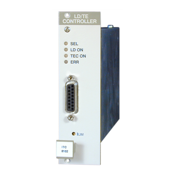
1.4 Operating elements at the front of the module Connector for the TEC element Connector for the laser diode Potentiometer for I Connector for both laser diode and TEC Figure 1 The ITC8xxx and ITC8xxxDS15 front panel ______________________________________________________________________________________________________ © 2010 Thorlabs... -
Page 19: Presettings
The value is displayed continually in the channel menu of the module so you can watch it during adjustment: (Refer to chapter 2.2, "Functions in the channel menu" starting on page29) = 0.0000 V CC off Imax= 200.0mA TH off I = 188.22mA CHANGE Hardware limit I _____________________________________________________________________________________________________ © 2010 Thorlabs... -
Page 20: Software Limits I Max
TE LIM hardware limit. (Refer to chapter 2.2, "Functions in the channel menu" starting on page 29) NOTE The lower of the two limits I or I will limit the laser diode current. ______________________________________________________________________________________________________ © 2010 Thorlabs... -
Page 21: Connecting Components
(Refer to 2.2.5, "Adjusting the bias voltage for the monitor diode" on page 33) The sensor input can handle different types of sensors. A missing sensor or selection of a wrong type is detected by the ITC8xxx. _____________________________________________________________________________________________________ © 2010 Thorlabs... -
Page 22: Pin Assignment Ld Connector
The shield has to be connected to ground (pin 3). If an external monitor diode is used, it must be connected with a coaxial cable with the outer conductor to pin 2 and the inner conductor to pin 4. ______________________________________________________________________________________________________ © 2010 Thorlabs... -
Page 23: Connecting Laser- And Monitor Diode
In this case the following pin assignments of the output jack are possible: (shown without voltage measurement) Figure 3 Pin assignments of laser- and photodiode (LD) = laser diode (PD) = monitor (photo-) diode _____________________________________________________________________________________________________ © 2010 Thorlabs... -
Page 24: Connecting Interlock And Status Led
Here are the two possibilities for the pin assignment: <430 Ω about 0.5 kΩ NOTE Using a resistor above 430 Ω- without LED (or if the LED is incorrectly poled) may lead to malfunction as the status of the interlock is then undefined. ______________________________________________________________________________________________________ © 2010 Thorlabs... -
Page 25: Pin Assignment Tec Connector
AD590 – (PT100 for ITC8xxxPT) AD590 + (PT100 for ITC8xxxPT) Connect the TEC element and the temperature sensor with shielded cables to the TEC connector. The shielding of the cable must be connected to ground (pin 13,14,15). _____________________________________________________________________________________________________ © 2010 Thorlabs... -
Page 26: Connecting A Thermistor
The thermistor is connected between pin 3 and pin 4. Figure 5 Connecting a thermistor 1.6.6 Connecting an AD590 The IC-temperature sensor AD590 is connected between pin 10 (-) and pin 11 (+). AD 590 Figure 6 Connecting an AD590 ______________________________________________________________________________________________________ © 2010 Thorlabs... -
Page 27: Connecting An Lm335
LM 335 Figure 7 Connecting an LM335 1.6.8 Connecting the TEC element Connect the TEC element to pins 5 and 6 (+) and the pins 13,14 and 15 for (-). Figure 8 Connecting a TEC element _____________________________________________________________________________________________________ © 2010 Thorlabs... -
Page 28: Polarity Check Of The Tec Element
To display the operating status of the temperature controller, a standard LED can be connected between pin 1 and pin 8 of the TEC connector (see “Pin assignment TEC connector”, page 19). The LED will light up if the output for the TEC current is switched on. ______________________________________________________________________________________________________ © 2010 Thorlabs... -
Page 29: Pin Assignment Itc8Xxxds15
Laser diode anode (polarity CG) Laser diode ground Laser diode cathode (polarity AG) Monitor diode Monitor diode ground Monitor diode anode or cathode / Bias Measurement input for laser diode voltage – (cathode) + (anode) Interlock Interlock Interlock ground _____________________________________________________________________________________________________ © 2010 Thorlabs... -
Page 30: Optimization Of Temperature Control
The sensor is never fixed directly to the laser chip to measure its “real” temperature. The inhomogeneous temperature in the copper bloc will influence the measurement. Even within the laser chip you will find a temperature gradient. Possible optimization: calibration of sensor ______________________________________________________________________________________________________ © 2010 Thorlabs... -
Page 31: Pid Adjustment
Increase the P-share gradually. Higher values will increase the settling speed, too high values make the system oscillate. The P-share has been set correctly when the actual temperature remains stable near the set temperature after only 2-3 overshoots. _____________________________________________________________________________________________________ © 2010 Thorlabs... - Page 32 Again change repeatedly between set temperatures of 18 °C and 22 °C. Increase the I-share gradually. Higher values will accelerate the settling to the set temperature. The I-share is set correctly when the actual temperature reaches the set temperature in shortest time without overshoots. ______________________________________________________________________________________________________ © 2010 Thorlabs...
-
Page 33: Operating The Itc8Xxx
T in °C. If the LD and TEC controllers are switched off, the set values (I ) are displayed. If one or both controllers are turned on the corresponding actual values appear (I _____________________________________________________________________________________________________ © 2010 Thorlabs... -
Page 34: Selecting A Module
To set the main parameter move the cursor to the desired channel number (here: CH1): 122.3mA +30.0°C TUNE Press the softkey (TUNE) to turn the cursor to the right: 122.3mA +30.0°C TUNE: Adjust the main parameter, here the laser diode current I , with the tuning knob. ______________________________________________________________________________________________________ © 2010 Thorlabs... -
Page 35: Functions In The Channel Menu
In the channel menu all parameters of the selected module are shown: channel no. cursor operating parameters = 44.000mA CC off P =0.70000mW TH off T = + 22.60°C CHANGE operating mode, laser on/off status field, TEC on/off _____________________________________________________________________________________________________ © 2010 Thorlabs... - Page 36 Dsh = 10.0 % Ishare ON Thermistor Rs = 10.000 kΩ = 40.959 kΩ = 0.200 kΩ Exponential R0 = 10.000 kΩ B = 3900.0 kΩ T0 = +25.00 °C C1 = 1.0628e-3 C2 = 2.4277e-4 C3 = 7.0471e-8 ______________________________________________________________________________________________________ © 2010 Thorlabs...
-
Page 37: Changing Parameters
Open interlock open laser diode output open laser on but current has reached the limit value TEC temperature out of activated temperature window Internal Power failure, contact Thorlabs fail over temperature wrong or no sensor connected SENS 2.2.2 Changing parameters... -
Page 38: Selecting The Polarity Of The Laser And The Monitor Diode
Adjust the desired value and terminate the procedure with (Refer to chapter 2.2.2, "Changing parameters" on page 31) The default value of η is 0.2000 A/W. It is valid without specific confirmation. ______________________________________________________________________________________________________ © 2010 Thorlabs... -
Page 39: Adjusting The Bias Voltage For The Monitor Diode
This is called constant power mode, Pconst. Select the parameter MODE = and toggle between Pconst (CP) and Cconst (CC). NOTE For "constant power" mode a monitor diode is necessary in the set-up. _____________________________________________________________________________________________________ © 2010 Thorlabs... -
Page 40: Selecting The Type Of The Sensor
In the channel menu you can choose between these two methods and enter the corresponding parameters: Select the line Steinh.-Hart resp. Exponential The right softkey toggles between the two methods. Select the desired type and press to make setting valid. ______________________________________________________________________________________________________ © 2010 Thorlabs... - Page 41 Steinhart-Hart ∗ ∗ (ln( with the three parameters C and C To change the three parameters select them one by one and set them to the desired value. Press to confirm each input. _____________________________________________________________________________________________________ © 2010 Thorlabs...
-
Page 42: Setting A Temperature Window
For adjustment of the parameters it is sometimes necessary to switch off the I-share completely. There is a separate switch parameter for this purpose: Ishare = ON/OFF You can toggle the function with the right softkey. Press to end the input. ______________________________________________________________________________________________________ © 2010 Thorlabs... -
Page 43: Switching On And Off
Due to a soft start function of the module, it takes about 1 second for the laser current to stabilize to the set value! _____________________________________________________________________________________________________ © 2010 Thorlabs... - Page 44 The LED “ON” at the module will light up when switched on and the status display changes from: TH off TH on In the main menu the set value T changes to the actual value T 122.3mA 30.20°C ______________________________________________________________________________________________________ © 2010 Thorlabs...
-
Page 45: Error Messages
Possible error messages of an ITC8xxx module: 1. in case of interrupted operation: Vcc fail Internal supply voltage failure. Please contact Thorlabs! Over Temperature Protection. Module has been switched off due to overheating. Operation is possible again after cooling down... - Page 46 3. when trying to switch on LD controller: Over Temperature Protection. Module is overheated and cannot be switched on. Vcc fail Internal supply voltage failure. Please contact Thorlabs! INTERLOCK Laser cannot be switched on due to interlock circuit interruption Twin Temperature is out of window (when window is activated) 4.
-
Page 47: Communication With A Control Computer
Program messages (PC ⇒ PRO8000 (-4)) are written in inverted commas: "*IDN?" Response messages (PRO8000 (-4) ⇒ PC) are written in brackets: [:SLOT 1] There is a decimal point: 1.234 "PLOT 2,0" Parameters are separated with comma: Commands are separated with semicolon: "*IDN?;*STB?" _____________________________________________________________________________________________________ © 2010 Thorlabs... -
Page 48: Data Format
14356.789432 (Refer to IEEE488.2 (8.7.3)) Numeric response data Type 3 (<NR3>) Is a numerical value with or without sign in floating point notation with exponent with sign. Examples: 1.1E+1 +1.1E-1 -22.1E+1 143.56789432E+306 (Refer to IEE488.2 (8.7.4)) ______________________________________________________________________________________________________ © 2010 Thorlabs... -
Page 49: Commands
Reading: ":CALPD:SET?" Reads the sensitivity (η) of the monitor diode [:CALPD:SET <NR3><LF>] ":CALPD:MIN?" Reads the minimum allowed sensitivity (η) of this module [:CALPD:MIN <NR3><LF>] ":CALPD:MAX?" Reads the maximum allowed sensitivity (η) of this module [:CALPD:MIN <NR3><LF>] _____________________________________________________________________________________________________ © 2010 Thorlabs... -
Page 50: Thermistor Calibration (Exponential Method)
If the last transmitted calibration command belongs to the exponential method (see above), then the calculation is also done with the exponential method. If the last command was a Steinhart-Hart parameter, then this method is chosen. ______________________________________________________________________________________________________ © 2010 Thorlabs... -
Page 51: Thermistor Calibration (Steinhart-Hart Method)
Reads the maximum C2 allowed [:CALTC2:MAX <NR3><LF>] ":CALTC3:MAX?" Reads the maximum C3 allowed [:CALTC3:MAX <NR3><LF>] (Refer to chapter 2.2.8.3, "Steinhart-Hart method" on page 35) For selection between both methods, see the note on the previous page! _____________________________________________________________________________________________________ © 2010 Thorlabs... -
Page 52: Programming The Laser Diode Current (Ild)
Reads the maximum laser diode current for Ild –ADC = FFFF [:ILD:MAX_R <NR3><LF>] ":ILD:START?" Reads the laser diode start current for “ELCH” [:ILD:START <NR3><LF>] ":ILD:STOP?" Reads the laser diode stop current for “ELCH” [:ILD:STOP <NR3><LF>] “ELCH”: Electrical CHaracterization ______________________________________________________________________________________________________ © 2010 Thorlabs... -
Page 53: Programming The Monitor Diode Current (Imd)
Reads minimum monitor diode current for Ipd –ADC = 0000 [:IMD:MIN_R <NR3><LF>] ":IMD:MAX_R?" Reads maximum monitor diode current for Ipd –ADC = FFFF [:IMD:MAX_R <NR3><LF>] ":IMD:START?" Reads the monitor diode start current for “ELCH” [:IMD:START <NR3><LF>] _____________________________________________________________________________________________________ © 2010 Thorlabs... -
Page 54: Switching The I-Share On And Off (Integ)
Reads the maximum TEC current for Ite –ADC = FFFF [:ITE:MAX_R <NR3><LF>] ":ITE:MEAS?" Reads the position of the TEC current as measurement value in the “ELCH” output string (1..8, 0 if not se- lected) [:ITE:MEAS <NR1><LF>] ______________________________________________________________________________________________________ © 2010 Thorlabs... -
Page 55: Switching The Laser Output On And Off (Laser)
Ilim – DAC = 0000 [:LIMC:MIN_W <NR3><LF>] ":LIMC:MAX_W?" Reads the laser diode current limit for Ilim – DAC = FFFF [:LIMC:MAX_W <NR3><LF>] (Refer to Chapter 1.5.2, "Software limits I and I " on page 14) TE LIM _____________________________________________________________________________________________________ © 2010 Thorlabs... -
Page 56: Reading The Laser Diode Hardware-Limit (Limcp)
I " on page 14) TE LIM 3.2.14 Selecting the mode of operation (MODE) Programming: ":MODE CC" Constant current mode ":MODE CP" Constant power mode Reading: ":MODE?" Reads the mode of operation [:MODE CC<LF>] [:MODE CP<LF>] ______________________________________________________________________________________________________ © 2010 Thorlabs... -
Page 57: Selecting The Photo Diode Polarity (Pdpol)
Reads the optical power for P – DAC = FFFF [:POPT:MAX_W <NR3><LF>] ":POPT:MIN_R?" Reads the optical power for P –ADC = 0000 [:POPT:MIN_R <NR3><LF>] ":POPT:MAX_R?" Reads the optical power for P –ADC = FFFF [:POPT:MAX_R <NR3><LF>] _____________________________________________________________________________________________________ © 2010 Thorlabs... -
Page 58: Programming The Resistance Of The Thermistor (Resi)
Reads R - DAC = FFFF [:RESI:MAX_W <NR3><LF>] ":RESI:MIN_R?" Reads R - ADC = 0000 [:RESI:MIN_R <NR3><LF>] ":RESI:MAX_R?" Reads R - ADC = FFFF [:RESI:MAX_R <NR3><LF>] ":RESI:MEAS?" Reads string position of R (1..8) for “ELCH” as measurement value [:RESI:MEAS <NR1><LF>] ______________________________________________________________________________________________________ © 2010 Thorlabs... -
Page 59: Programming The Resistance Window (Rwin)
Reads Rwin - DAC = FFFF [:RWIN:MAX_W <NR3><LF>] 3.2.19 Selecting the sensor (SENS) Programming: ":SENS AD" Sensor is AD590 family ":SENS TH" Sensor is thermistor Reading: ":SENS?" Reads the actual sensor type [:SENS AD<LF>] [:SENS TH<LF>] _____________________________________________________________________________________________________ © 2010 Thorlabs... -
Page 60: Programming The Pid Shares (Sharep, -I, -D)
(Refer to chapter 1.7.2, "PID adjustment" on page 25) 3.2.21 Switching the TEC on and off (TEC) Programming: ":TEC ON" Switch the TEC output on ":TEC OFF" Switch the TEC output off Reading: ":TEC?" Reads status of the output [:TEC ON<LF>] [:TEC OFF<LF>] ______________________________________________________________________________________________________ © 2010 Thorlabs... -
Page 61: Programming The Temperature (Temp)
[:TEMP:MEAS <NR1><LF>] 3.2.23 Switching the temperature protection on and off (TP) Programming: ":TP ON" Switch temperature protection on ":TP OFF" Switch temperature protection off Reading: ":TP?" Reads status of the temperature protection [:TP ON<LF>] [:TP OFF<LF>] _____________________________________________________________________________________________________ © 2010 Thorlabs... -
Page 62: Programming The Temperature Window (Twin)
Reads the maximum allowed set temperature window [:TWIN:MAX <NR3><LF>] ":TWIN:MIN_W?" Reads Twin - DAC = 0000 [:TWIN:MIN_W <NR3><LF>] ":TWIN:MAX_W?" Reads Twin - DAC = FFFF [:TWIN:MAX_W <NR3><LF>] 3.2.25 Read Type of module (TYPE) "TYPE ID?" Reads module identification (here 159) [:TYPE 159<LF>] ______________________________________________________________________________________________________ © 2010 Thorlabs... -
Page 63: Programming The Bias Voltage (Vbias)
- DAC = 0000 BIAS [:VBIAS:MIN_W <NR3><LF>] ":VBIAS:MAX_W?" Reads U - DAC = FFFF BIAS [:VBIAS:MAX_W <NR3><LF>] ":VBIAS:START?" Reads the bias start voltage for “ELCH” [:VBIAS:START <NR3><LF>] ":VBIAS:STOP?" Reads the bias stop voltage for “ELCH” [:VBIAS:STOP <NR3><LF>] _____________________________________________________________________________________________________ © 2010 Thorlabs... -
Page 64: Reading The Laser Diode Voltage (Vld)
[:VTE:ACT <NR3><LF>] ":VTE:MIN_R?" Reads U – ADC = 0000 [:VTE:MIN_R <NR3><LF>] ":VTE:MAX_R?" Reads U – ADC = FFFF [:VTE:MAX_R <NR3><LF>] ":VTE:MEAS?" Reads string position (1..8) of peltier voltage as measurement value for “ELCH” . [:VTE:MEAS <NR1><LF>] ______________________________________________________________________________________________________ © 2010 Thorlabs... -
Page 65: Ieee Error Messages Of The Itc8Xxx
Over Temperature Protection. Module is overheated and cannot be switched on. [1304,"Internal power failure"] Possible reason: Severe hardware error. Contact Thorlabs. [1305,"No calibrating of sensor during TEC on"] Reason: The sensor cannot be calibrated when TEC controller is switched [1306,"No calibrating of PD during laser on in constant power mode"]... - Page 66 Attempt to switch on the laser while the laser temperature is outside of the temperature window. [1316,"Attempt to activate Twin during laser on"] Possible reason: The temperature window cannot be activated when the laser output is switched on. ______________________________________________________________________________________________________ © 2010 Thorlabs...
-
Page 67: Status Reporting
(Please refer to the IEEE488.2-1992 standard chapter 11) No or wrong senso Open circuit (TEC) Current limit Interlock open Open circuit (LD) (:S TAT:DECn?) n: Slot num ber Figure 11 The ITC8xxx device error registers DEC, DEE and EDE _____________________________________________________________________________________________________ © 2010 Thorlabs... - Page 68 Status reporting _________________________________________________________________________________ Output buffer ERROR Queue or serial poll Service Request Generation Figure 12 The PRO8000 (-4) / PRO800 register ESR, ESE, STB and SRE ______________________________________________________________________________________________________ © 2010 Thorlabs...
-
Page 69: Standard Event Status Register (Esr)
“OR”-function, so that any "hit" leads to a logical 1 in bit 5 (ESB) of the STB. As any bit of the STB can assert an SRQ, every event (bit of the ESR) can be used to assert an SRQ. _____________________________________________________________________________________________________ © 2010 Thorlabs... -
Page 70: Status Byte Register (Stb)
If the controller does not "listen" to SRQ’s at all, the service request can be detected by reading the status byte with the command "*STB?". If bit 6 is logical 1, a service request was asserted. ______________________________________________________________________________________________________ © 2010 Thorlabs... -
Page 71: Reading The Stb By Serial Poll
8 bits of the DEE. These 8 results are combinedned by logical "OR", so that any "hit" leads to a logical 1 in bit 3 (DES) of the STB. As any bit of the STB can assert an SRQ, every error (bit of the DEE) can be used to assert an SRQ. _____________________________________________________________________________________________________ © 2010 Thorlabs... -
Page 72: Service And Maintenance
4 Service and Maintenance 4.1 General remarks The ITC8xxx modules do not need any maintenance by the user. In order to ensure best performance, accuracy and reliable operation, Thorlabs recommends a recalibration cycle of 24 months. 4.2 Troubleshooting In case that your PRO8000 / PRO800 system shows malfunction please check the... - Page 73 Turn off bias voltage in the channel menu, with the command or change the polarity of the diode for photo element mode. Is the correct photo diode efficiency set (A/W)? Enter the coefficient in the channel menu or with the command ":CALPD:SET" _____________________________________________________________________________________________________ © 2010 Thorlabs...
- Page 74 Set temperature differs from actual temperature (of the laser) Is the sensor calibrated properly? Enter precise calibration factors (thermistor). Refer to section 2.2.8. If this does not help to resolve your trouble, please contact Thorlabs’ Tech Support (see section 5.7, “Addresses ” on page 77). ______________________________________________________________________________________________________ ©...
-
Page 75: Appendix
For warranty repairs or service the unit must be sent back to Thorlabs (Germany) or to a place determined by Thorlabs. The customer will carry the shipping costs to Thorlabs, in case of warranty repairs Thorlabs will carry the shipping costs back to the customer. -
Page 76: Thorlabs "End Of Life" Policy (Weee)
5.2.1 Waste treatment on your own responsibility If you do not return an “end of life” unit to Thorlabs, you must hand it to a company specialized in waste recovery. Do not dispose of the unit in a litter bin or at a public waste disposal site. -
Page 77: Ecological Background
Thorlabs “End of Life” policy (WEEE) _________________________________________________________________________________ 5.2.2 Ecological background It is well known that WEEE pollutes the environment by releasing toxic products during decomposition. The aim of the European RoHS directive is to reduce the content of toxic substances in electronic products in the future. -
Page 78: List Of Acronyms
Integral share Laser Diode Controller Light Emitting Diode Line Feed Local Lockout Numeric Response data of type 1 Numeric Response data of type 2 Numeric Response data of type 3 Message AVailable) Master Summary Status Over TemPerature ______________________________________________________________________________________________________ © 2010 Thorlabs... - Page 79 List of acronyms _________________________________________________________________________________ Personal Computer P-Share Proportional share ReQuest Service Message Selected Device Clear SELect Service Request Enable Register Service ReQuest STatus Byte Register Soft Ware ThermoElectric Cooler (Peltier Element) TRiGger _____________________________________________________________________________________________________ © 2010 Thorlabs...
-
Page 80: List Of Figures
Figure 11 The ITC8xxx device error registers DEC, DEE and EDE ....61 Figure 12 The PRO8000 (-4) / PRO800 register ESR, ESE, STB and SRE ... 62 Figure 13 Crossed out “wheelie bin” symbol ........... 71 ______________________________________________________________________________________________________ © 2010 Thorlabs... -
Page 81: Certifications And Compliances
LD OUT and TEC OUT ports. ITC8022 testing included a LAB8000 Laser Diode Mount Box attached at the other end of the CAB4x cable. Compliance demonstrated with the ITC8x series modules installed in Thorlabs PRO8x series mainframes. -
Page 82: Copyright
User Manual. Should you require further information on this product, or encounter specific problems that are not discussed in sufficient detail in the User Manual, please contact your local Thorlabs dealer or system installer. -
Page 83: Addresses
Newton, NJ 07860 Sales and Support Phone: +1-973-579-7227 Fax: +1-973-300-3600 Email: sales@thorlabs.com techsupport@thorlabs.com Web: www.thorlabs.com Japan Thorlabs Japan Inc. Higashi Ikebukuro Q Building 1st floor 2-23-2 Toshima-ku, Tokyo 170-0013 Japan Sales and Support Phone: +81-3-5979-8889 Fax: +81-3-5979-7285 Email: sales@thorlabs.jp Web: www.thorlabs.jp... - Page 84 Web: www.thorlabs.com Our company is also represented by several distributors and sales offices throughout the world. Please call our hotline, send an Email to ask for your nearest distributor or just visit our homepage http://www.thorlabs.com ______________________________________________________________________________________________________ © 2010 Thorlabs...
Need help?
Do you have a question about the ITC8 Series and is the answer not in the manual?
Questions and answers