Table of Contents
Advertisement
Quick Links
Advertisement
Table of Contents

Related Manuals for THORLABS PBM42


Summary of Contents for THORLABS PBM42
- Page 1 PBM42 Photodiode Bias Module For Mounted Photodiodes User Guide...
-
Page 2: Table Of Contents
Chapter 8 Specifications ..............14 Chapter 9 Mechanical Drawing ............15 Chapter 10 Regulatory ................ 16 10.1. Waste Treatment is Your Own Responsibility .... 16 10.2. Ecological Background .......... 16 Chapter 11 Thorlabs Worldwide Contacts ........17 ... -
Page 3: Chapter 1 Warning Symbol Definitions
PBM42 Chapter 1: Warning Symbol Definitions Chapter 1 Warning Symbol Definitions Below is a list of warning symbols you may encounter in this manual or on your device. Symbol Description Direct Current Alternating Current Both Direct and Alternating Current Earth Ground Terminal... -
Page 4: Chapter 2 Safety
PBM42 Chapter 2: Safety Chapter 2 Safety CAUTION Using the PBM42 to forward bias the photodiode can damage the photodiode. Page 2 TTN029240-D02... -
Page 5: Chapter 3 Description
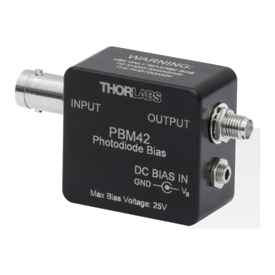
Chapter 3: Description Chapter 3 Description The PBM42 Photodiode Bias Module is designed to be used with the Thorlabs SM05PDxx and SM1PDxx Mounted Photodiodes. The output uses a female SMA connector to minimize size. The mounted photodiodes are connected to the input female BNC connector with a cable or an adapter. -
Page 6: Chapter 4 Setup
PH-series post holder. Connect the mounted photodiode to the module. For a direct connection, Thorlabs offers the T3533 adapter. For connection via a cable, the 2249-C- xx is available. Connect an SMA cable to the output end of the module. Depending on your application and voltage measurement device, select and install a terminating resistor. -
Page 7: Chapter 5 Operation
Depicted in Figure 1 is a junction photodiode model with basic discrete components to help visualize the main characteristics and gain a better understanding of the operation of Thorlabs' photodiodes. ��... -
Page 8: Photoconductive
PBM42 Chapter 5: Operation 5.3.1. Photoconductive In photoconductive mode, a reverse external bias is applied, which is the basis for our mounted series detectors. The current measured through the circuit indicates illumination of the device; the measured output current is linearly proportional to the input optical power. -
Page 9: Junction Capacitance
PBM42 Chapter 5: Operation The table below gives some advantages to each common type of detector material. Dark Sensitivity Material Current Speed (nm) Cost Silicon (Si) High 400 – 1000 Germanium (Ge) High 900 – 1600 Gallium Phosphide (GaP) High 150 –... -
Page 10: Terminating Resistance
PBM42 Chapter 5: Operation 5.7. Terminating Resistance We use a load resistance to convert the generated photocurrent into a voltage ) for viewing on an oscilloscope: �� �� �� Depending on the type of the photodiode, load resistance can affect the response speed. -
Page 11: Bias Power Supply And Cable
Chapter 5: Operation 5.11. Bias Power Supply and Cable Thorlabs delivers each PBM42 module with a 2.5 mm sub-mini phono plug with a three foot power cable for connection to the user supplied power supply. It is recommended to use a well regulated, low noise power supply for biasing the photodiodes. -
Page 12: Chapter 6 Common Operating Circuits
PBM42 Chapter 6: Common Operating Circuits Chapter 6 Common Operating Circuits RC Filter External Protection Diode Photodetector Voltage Resistor V Bias Regulator 1 kΩ On/Off Switch LOAD Capacitor 0.1 µF Battery Figure 2 Basic DET Circuit The DET Series Detectors are designed according the circuit depicted above. - Page 13 PBM42 Chapter 6: Common Operating Circuits We can achieve high gain when using a photo detector with an amplifier. The user can choose whether to operate in Photovoltaic of Photoconductive modes. There are a few benefits of choosing this active circuit: ...
- Page 14 Bias Polarity For Grounded Anode – Grounded Cathode (Mounted Photodiode) PBM42 Photo Detector (Output to Load Resistor/ Oscilloscope) Capacitor 0.1 µF Resistor 1 kΩ Bias Jack Bias Polarity For Grounded Cathode – Figure 4 PBM42 Circuit Diagram Page 12 TTN029240-D02...
-
Page 15: Chapter 7 Troubleshooting
Verify that the optical signal is illuminating the detector active area. Connect the PBM42 to an oscilloscope without a terminating resistor installed. Most general purpose oscilloscopes will have a1 MΩ input impedance. Point the detector toward a fluorescent light and verify that a 60 Hz (50 Hz outside the US) signal appears on the scope. -
Page 16: Chapter 8 Specifications
Chapter 8 Specifications All measurements performed with a 50 Ω load unless stated otherwise. Electrical Specifications Parameter Symbol Value Detectors Thorlabs Mounted Photodiodes Wavelength Range λ 150 to 1800 nm Cutoff Frequency 350 MHz (Typ.) Bias Voltage -25 to +25 V... -
Page 17: Chapter 9 Mechanical Drawing
PBM42 Chapter 9: Mechanical Drawing Chapter 9 Mechanical Drawing Rev D, May 10, 2022 Page 15... -
Page 18: Chapter 10 Regulatory
10.1. Waste Treatment is Your Own Responsibility If you do not return an “end of life” unit to Thorlabs, you must hand it to a company specialized in waste recovery. Do not dispose of the unit in a litter bin or at a public waste disposal site. -
Page 19: Chapter 11 Thorlabs Worldwide Contacts
PBM42 Chapter 11: Thorlabs Worldwide Contacts Chapter 11 Thorlabs Worldwide Contacts For technical support or sales inquiries, please visit us at www.thorlabs.com/contact for our most up-to-date contact information. USA, Canada, and South America UK and Ireland Thorlabs, Inc. Thorlabs Ltd. - Page 20 www.thorlabs.com...
Need help?
Do you have a question about the PBM42 and is the answer not in the manual?
Questions and answers