
Related Manuals for THORLABS ECL1525M-PM


Summary of Contents for THORLABS ECL1525M-PM
- Page 1 Operation Manual Digitally Controlled Continously Tunable Laser ECL ECL1525M-PM/SM 2005...
- Page 2 Version: Date: 16-Feb-05 © Copyright 2005, Thorlabs Sweden AB, Sweden...
-
Page 3: Table Of Contents
Contents Page General description 1.1 Safety 1.2 Warranty 1.3 Features 1.4 Technical data Mechanical Interface 2.1 Size 2.2 Electrical Connector 2.3 Optical Connector 2.4 Thermal management 2.5 Vibration damping Electrical interface 3.1 Connector pinout 3.2 Pin function 3.3 Electrical characteristics 3.4 Communication interface Operating the ECL1525-PM/SM 4.1 System Organization... - Page 4 Therefore, please let us know about possible criticism or ideas. We and our international partners are looking forward to hearing from you. Thorlabs Sweden AB This part of the instruction manual contains every specific information on how to operate a ECL1525. A general description is followed by explanations of how to operate the unit manually.
-
Page 5: General Description
Applicable EMC standards are: Emission according to EN 550022 class B Immunity according to EN 61000-4-3 (10V/m), EN 61000-4-8 (30A/m) and EN 61000-4-2 (4kV contact / 8kV air) Attention Applicable safety standards are: EN 61010-1 and UL 3101-1 ECL1525M-PM/SM / page 1... - Page 6 1.1 Safety ECL1525M-PM/SM / page 2...
-
Page 7: Warranty
Thorlabs Sweden AB reserves the right to change this instruction manual or the technical data of the described unit at any time. ECL1525M-PM/SM / page 3... -
Page 8: Features
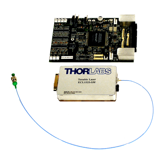
RS232 or via a user’s PC. The ECL1525 is available in three package styles, see the figures below. This manual is valid for the module (ECL1525M-SM and ECL1525M-PM) Figure 1. Pictures of the different packages:Benchtop (ECL1525), Module with control PCB (ECL1525M) and Eurocard module (ECL1525-3U) . -
Page 9: Technical Data
<15W -25 … +70 °C Transport temperature +5 … +60 °C Operating temperature (Case temperature) Altitude/Pressure Operational 70 .. 106 kPa (about 0-3000m altitude) Weight (Module+Electronics) 0.65+0.15 kg Width (W x H x D) 113x50x180 mm ECL1525M-PM/SM / page 5... - Page 10 9 to 200 Hz 15m/s 200 to 500 Hz Vibration Transport 20m/s 9 to 200 Hz 45m/s 200 to 500 Hz Shock Operation, half sinusoidal 300 m/s , duration 6ms Shock Transport, half sinusoidal 1000 m/s , duration 6ms ECL1525M-PM/SM / page 6...
-
Page 11: Mechanical Interface
2.1 Size 2 Mechanical Interface 2.1 Size Optical Module: ECL1525M-PM/SM / page 7... - Page 12 2.1 Size Electronic Control Board ECL1525M-PM/SM / page 8...
-
Page 13: Electrical Connector
2.5 Vibration damping The optical module is mounted with vibration dampers in the ECL1525 and in the ECL1525-U. Similar vibration dampers are required for the ECL1525M in a customers system if specified vibration levels should apply. ECL1525M-PM/SM / page 9... -
Page 15: Electrical Interface
The standard connector on the electronic has a pinnout according to table 1. Tabel 1 Connector pinnout. The symbol * indicates signals that are defined as active when low. Pin # Pin # DIS* RST* SRQ* FATAL* ALM* TRST (JTAG) IRDY* ADITHER MotorCLK LaserCurrent LaserPower MeasGround +WaveClock -WaveClock ECL1525M-PM/SM / page 11... - Page 16 Tabel 2. Connector pinout. The symbol * indicates signals that are defined as active when low. Pin # Pin # DIS* RST* SRQ* FATAL* ALM* TRST (JTAG) IRDY* IOCLK Not used ( IOMODE IOMODE1 ADITHER MotorCLK LaserCurrent Reserved LaserPower Reserved MeasGround Reserved +WaveClock Reserved -WaveClock Reserved ECL1525M-PM/SM / page 12...
-
Page 17: Pin Function
Power supply noise (for %rms power supplied to the module) (100Hz-20MHz) Analog Input VAPOWMOD Vp-p Power voltage Modula- -3dB FAPOWMOD 1000 tion Input Bandwidth ZAPOWMOD 10000 Input 5000 ohms impedance LaserCurrent Vlasercurrent LaserPower Vlaserpower WaveClock Vwclock ECL1525M-PM/SM / page 13... -
Page 18: Communication Interface
The interface for the benchtop option (ECL 1525) or the evaluation board is a nullmodem DB-9 cable that you connect directly to the computer. For the other options (ECL1525M,ECL1525-3U) the interface is RS232 that uses a 3- wire implementation according to MSA. The interface generates LVTTL output signal levels. ECL1525M-PM/SM / page 14... -
Page 19: Operating The Ecl1525-Pm/Sm
Commands given by the GUI or another user application are decomposed into the main hardware commands executed by the the control card. Users that want to develop their own application software can use the drivers that are compile in dynamic link libraries (.dll). ECL1525M-PM/SM / page 15... -
Page 20: Software Installation
“drv_uECL_msa_dll_Destroy.vi” at the end. On standard error the driver ignores all further commands, but the handle will still be closed by “drv_uECL_msa_dll_Destroy.vi”. In the table below is som common variables listed: ReadWrite Selects whether the command should read or write ECL1525M-PM/SM / page 16... - Page 21 Stores the 100 last messages, last one first. The file drv_µECL_msa_dll_Tree.vi contains uECL customer LabView driver VI:s. There is a short description of each command in the VI descriptions. See also the example in section 6.4. Front Panel Block Diagram ECL1525M-PM/SM / page 17...
-
Page 22: Getting Started
If you turn the laser off it has to go through the start-up sequence again which takes about one minute. You can also change into sweep mode and then adjust sweep range and speed. For more details see chapter 5. ECL1525M-PM/SM / page 18... -
Page 23: Ecl1525 Operation In Detail
“start wavelength” and “stop wavelength” controls. Even if these controls can be changed during sweeping, the actual sweep range will not be updated until the tuning is stopped and then started again. The tuning speed can also be changed when the sweep is stopped. ECL1525M-PM/SM / page 19... -
Page 24: The Control Windows
The Pending indicator shows if the laser unit is under operation. The Fatal, ALM (alarm) and SRQ (service request) are signals that indicate that something is wrong with the laser. CE indicates communication error. XE indicates execution error. ECL1525M-PM/SM / page 20... - Page 25 In the mode of analog dither you have to use an external source connected to the ADITHER pin in the connector. Wavelength Power f=15kHz 2=100MHz (0.8pm) Power 1=50MHz (0.4pm) AM amplitude (%) level 1/ (AM Frequency) time time ECL1525M-PM/SM / page 21...
- Page 26 This window is intended for advanced status information. It can be used for trouble shooting and is not used for standard operation of the laser. You can also change the function of the MotorCLK pin between direction and motorclock . ECL1525M-PM/SM / page 22...
-
Page 27: Software Interface
See MSA command 0x08 AEA EAR See MSA command 0x0B 6.2.2 Module Status Commands Command StatusF See MSA command 0x20 StatusW See MSA command 0x21 FpowTh See MSA command 0x22 WPowTh See MSA command 0x23 RCS not implemented ECL1525M-PM/SM / page 23... - Page 28 See MSA command 0x55 6.2.5 MSA Commands Command DitherE See MSA command 0x59 DitherR See MSA command 0x5A Can be pending SR not implemented WF not implemented. Power modulation waveform is square. Frequency modulation waveform is triangle. ECL1525M-PM/SM / page 24...
- Page 29 6.2 MSA Commands DitherF See MSA command 0x5B DitherA See MSA command 0x5C TCaseL See MSA command 0x5D TCaseH See MSA command 0x5E ECL1525M-PM/SM / page 25...
-
Page 30: Ecl1525 Specific Commands
Can be Volatile? Default name number Write Generated pending? Access? contents TStop 0x81 Unsigned Non- 0x0001 short volatile Unsigned Lockable 1 short Returns Same as the Channel (0x30) command. Detailed description The tuning range is defined as: ECL1525M-PM/SM / page 26... - Page 31 Access? contents TSset 0x82 Unsigned Non- 0x0064 short volatile Unsigned Lockable 1 short Returns Same as the Channel (0x30) command. Detailed description Bit 6:0 Speed Bit 6:0 The speed is defined as: v *Speed/10000. λ ECL1525M-PM/SM / page 27...
- Page 32 A ”1” sets the mode where channel sweep between the channels specified in the Tuning Range Set register with the speed specified in the Tuning Speed Set register. Bit 0 SS-Start/Stop (default=0) A ”0” sets the normal mode where the tuning is stopped. A ”1” starts the tuning. ECL1525M-PM/SM / page 28...
- Page 33 Purpose: OER returns the ratio between etalon power and the reference optical power. Synopsis Register Register Read/ Datatype Response Can be Volatile? Default name number Write Generated pending? Access? contents 0x8A Unsigned Volatile short Returns Same as the Channel (0x30) command. Detailed description 13:0 Optical Etalon Ratio ECL1525M-PM/SM / page 29...
- Page 34 A “0” sets the direction mode. The motorCLK pin is then high when the channel number is increasing and low when it is decreasing. A ”1” sets the stepclock mode. The motor clock pin then gives a 100ns pulse for every motor step (about 1 pm). ECL1525M-PM/SM / page 30...
-
Page 35: Application Example
WaveClock ( pin 37 and 39). The standard version does not include a shutter. Therefore if the optical output has been disabled before the registers are set according to the table above, will the reset take a few seconds. ECL1525M-PM/SM / page 31... - Page 36 This section contains LabView code based on the application example in chapter 6.4.1. Front Panel Block Diagram 6 7 8 Sequence: 1.Open handle 2.Set parameters 3.Enable laser output 4.Start sweep 5.Log status until “Stop” is pressed (or error occurs) 6.Stop sweep 7.Disable laser output 8.Close handle ECL1525M-PM/SM / page 32...
-
Page 37: Service And Maintenance
3. Check that the connector is clean and that the connecting fiber is not damaged. 4. Check the Case Temp in the advanced window. If this is over 60 ° C the module is to hot. ECL1525M-PM/SM / page 33... -
Page 39: Listings
8.1 References 8 Listings 8.1 References 1. The OIF Compliant Tunable MSA . Public document release PV:1.2.3 This document is included on the CD. Updated information about this standard can be found at: http://www.oiforum.com/public/impagreements.html#TL ECL1525M-PM/SM / page 35... -
Page 40: Addresses
Fax: +46 (0)13 703 40 45 Email: scandinavia@thorlabs.com Internet: http://www.thorlabs.com Our company is also represented by several distributors throughout the world. Please call our hotline, send an E-mail to ask for your nearest distributor or just visit our homepage http://www.thorlabs.com ECL1525M-PM/SM / page 36...
Need help?
Do you have a question about the ECL1525M-PM and is the answer not in the manual?
Questions and answers